Alciatore D.G., Histand M.B. Introduction to Mechatronics and Measurement Systems
Подождите немного. Документ загружается.

Confirming Pages
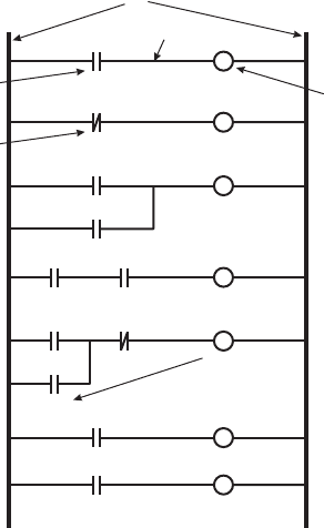
Figure 11.1 Ladder logic symbols and basic functions .
rails
rung
NO input
I
1
O
1
outpu
t
NC input
I
2
O
2
I
3
O
3
I
4
OR logic
AND logic
I
5
O
4
I
6
I
8
latching
circuit
I
7
O
5
I
9
O
5
output relay
timer
timer
timer
O
6
11.2 Control Architectures 481
the rails on the ladder represent power (on the left) and ground (on the right), and the
rungs represent current-flow paths (from left to right) to output devices. An input is
typically a switch or proximity sensor that is represented by a normally open (NO)
or normally closed (NC) relay symbol. Inputs can be arranged in series and parallel
configurations in a rung to represent various logic functions. An output is included
on the right side of a rung, and it is energized when the input relays on the left side of
the rung result in a closed circuit. An output can be a motor, heater, lamp, solenoid,
or other controlled device. An output state can also be used as an input relay to con-
trol other rungs in the ladder. Special features such as timers and counters are also
available to create sequencing, stopping, and restarting of a series of events.
In Figure 11.1 output O
1
is energized only while No input I
1
is closed. I
2
is an
NC input, and output O
2
is off when I
2
is open. Output O
3
is energized only while
NO input I
3
is closed or NO input I
4
is closed. Output O
4
is energized only while NO
input I
5
is closed and NO input I
6
is closed. The O
5
rung is called a latching circuit.
It is triggered (i.e., O
5
is energized) when NO input I
7
is closed. Also, once trig-
gered, the output remains energized, even if input I
7
returns to the open state, until
NC input I
8
opens. This is accomplished by using the output signal as an additional
input (called an output relay ) OR’d with the trigger input I
7
. The term latch is used
because the output’s ON state is maintained (stored) until it is reset by a second input
( I
8
). The last two rungs show how a timer is used. When NO input I
9
closes, a timer
is started. When the timer reaches a preprogrammed period, the timer input closes,
energizing output O
6
.
alc80237_ch11_478-522.indd 481alc80237_ch11_478-522.indd 481 10/01/11 8:27 PM10/01/11 8:27 PM
Confirming Pages
482 CHAPTER 11 Mechatronic Systems—Control Architectures and Case Studies
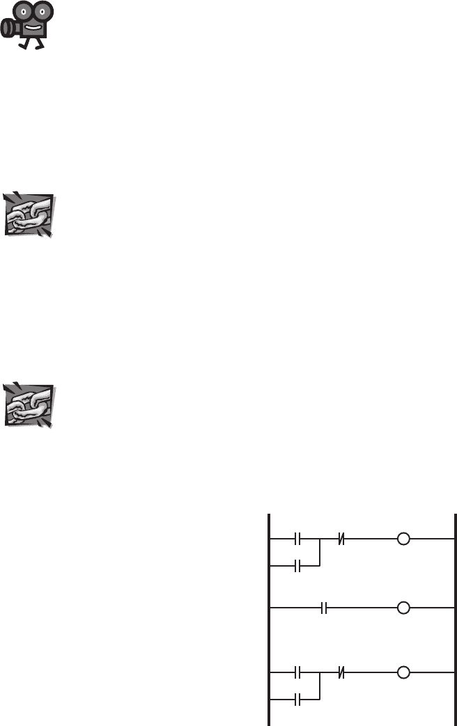
Figure 11.2 shows an example ladder logic diagram for a common assembly-
line control system where a motor or double-acting pneumatic or hydraulic cylinder
is actuated back and forth based on a trigger event (e.g., a widget being detected
by a proximity sensor next to a conveyor belt). Limit switches or sensors detect
the desired ends of travel of the actuator in each direction. Here is the sequence of
events: when the NO “trigger” input closes, the actuator is driven in the forward
direction. The latching circuit maintains this forward motion until the NC “end limit
detect” signal changes state. This opens the NC “end limit detect” input in the first
rung and closes the NO “end limit detect” input in the second rung, which starts
the timer. When the timer reaches its preset time, the third rung is triggered and the
actuator reverses until the NC “start limit detect” signal is detected. In summary,
when triggered, the actuator moves forward until the end of travel is detected, then
the system pauses before returning the actuator back to the start position.
Video Demo 11.2 shows an example PLC development system and demon-
strates how ladder logic can be used to create a fluid-level control system, and Video
Demo 11.3 shows an interesting student project example using a PLC. Internet
Link 11.1 provides links to various online resources for and manufacturers of PLC
products, and Internet Link 11.2 provides an excellent set of tutorials on various
PLC topics.
11.2.4 Microcontrollers and DSPs
The microcontroller, which is a microcomputer on a single IC, provides a small,
flexible control platform that can be easily embedded in a mechatronic system.
The microcontroller can be programmed to perform a wide range of control tasks.
Designing with microcontrollers usually requires knowledge of a high-level pro-
gramming language (e.g., C or Basic) or assembly language and experience in inter-
facing digital and analog devices. See Chapter 7 for background information and
examples. Internet Link 7.1 provides links to various online resources for and manu-
facturers of microcontrollers.
Video Demo
11.2Program-
mable logic
controller with
ladder logic
11.3PLC infant
formula machine
Internet Lin
k
11.1Program-
mable logic
controller online
resources and
manufacturers
11.2PLC tutorial
Figure 11.2 Ladder logic motor control cycle example .
actuator
forward
timer
trigger
end limit
detect
actuator
forward
end limit
detect
actuator
reverse
timer
start limit
detect
actuator
reverse
Internet Lin
k
7.1Microcon-
troller online
resources and
manufacturers
alc80237_ch11_478-522.indd 482alc80237_ch11_478-522.indd 482 10/01/11 8:27 PM10/01/11 8:27 PM

Confirming Pages
11.3 Introduction to Control Theory 483
Another type of single-IC microcomputer device is a digital signal proces-
sor ( DSP ). A DSP can have functionality similar to that of a microcontroller,
but DSPs are usually better suited to high-speed floating point calculations.
DSPs are useful in communication, audio/video, and control applications where
fast calculation of digital filters and weighted sums is important for fast cycle
times. Internet Link 11.3 provides links to various DSP online resources and
manufacutrers.
11.2.5 Single-Board Computer
When an application requires more features or resources than can be found on a
typical microcontroller and size is not a major concern, a single-board computer
offers a good alternative. Most single-board computers have enough RAM and offer
compilers to support programming in a high-level language such as C. Single-board
computers are also easily interfaced to a personal computer. This is useful in the test-
ing and debugging stages of design development and for downloading software into
the single-board computer’s memory.
We use the term minicontroller to refer to another class of device that
falls between a microcontroller and a single-board computer. Examples are the
Handyboard, Basic Stamp, and Arduino. These boards contain microcontrollers and
other peripheral components that make it easier to interface to external components.
Internet Link 11.4 provides links to online resources for single-board computer and
mini-controller products.
11.2.6 Personal Computer
In the case of large sophisticated mechatronic systems, a desktop or laptop personal
computer (PC) may serve as an appropriate control platform. Also, for those not
experienced with microcontrollers and single-board computers, the PC may be an
attractive alternative. The PC can be easily interfaced to sensors and actuators using
commercially available plug-in data acquisition cards or modules (see Section 8.3).
These devices typically include software drivers that enable programming with stan-
dard high-level language compilers and development environments. Due to the ease
and convenience of this approach, PC-controlled mechatronic systems are especially
common in R&D testing and product development laboratories, where fast proto-
typing is required but where large-quantity production and miniaturization are not
concerns.
11.3 INTRODUCTION TO CONTROL THEORY
In mechatronic system design, we often need to accurately control an output (e.g.,
the position or speed of a motor’s shaft) with fast response. An impressive exam-
ple of position control is shown in Video Demo 10.3, where the read-write head of
a computer hard drive is controlled with amazing speed and accuracy (see Video
Demo 10.4 for a super-slow-motion playback of the motion). For accurate control,
Internet Lin
k
11.3Digital
signal processor
resources and
vendors
Internet Lin
k
11.4Single-
board computer
and minicontroller
online resources
and vendors
Video Demo
10.3Computer
hard-drive track
seeking
demonstration
10.4Computer
hard-drive super-
slow-motion video
of track finding
alc80237_ch11_478-522.indd 483alc80237_ch11_478-522.indd 483 10/01/11 8:27 PM10/01/11 8:27 PM

Confirming Pages
484 CHAPTER 11 Mechatronic Systems—Control Architectures and Case Studies
we need to use feedback from sensors (e.g., an encoder or a tachometer). By sub-
tracting a feedback signal from a desired input signal (called the set point value), we
have a measure of the error in the response. By continually changing the command
signal to the system based on the error signal, we can improve the response of the
system. This is called feedback or closed-loop control. The goal of this section is to
introduce the basics of feedback control system design.
The theory and practice of control system design can be very complicated and
may involve some mathematical techniques and software tools with which you
might not be familiar. However, it is important for the reader to understand the
approach to control system design, first to appreciate the value of its application
and second to develop a desire to learn more about the field of controls (e.g., via
follow-on coursework). In the subsections that follow, we explore the concepts of
feedback control through a basic but important example of controlling the speed of
a DC motor.
Before continuing, you may want to view Video Demos 11.4 and 11.5. They
demonstrate two laboratory experiments that illustrate various control system topics.
These examples might help you better relate to the material presented in this sec-
tion. Video Demo 11.3 does a particularly good job of explaining some of the basic
principles of proportional-integral-derivative (PID) control, which forms the basis of
many control systems.
11.3.1 Armature-Controlled DC Motor
An important electromechanical device that is incorporated into many mechatronic
systems is a permanent magnet or field-controlled DC motor. In mechatronic system
applications, we might need to carefully control the output position, speed, or torque
of the motor to match design specifications. This is a good example where feedback
control is required. Our first problem, as in every mechatronic control system, is to
model the motor. The model of a physical system is often referred to as the plant.
Then we apply linear feedback analysis to the problem to help in selecting the design
parameters for a controller that will reasonably track the desired output (specified
input). We must create a good mathematical model of the motor (the system model)
before we continue with controller design.
The basic equations governing the response of a DC motor were presented in
Section 10.5, but we will take the analysis further here. A DC motor has an armature
with inductance L and resistance R, such that when it rotates in a magnetic field,
the armature will produce an output torque and angular velocity. Due to the motor
construction, a back emf (voltage) proportional to angular velocity is caused by the
armature coils moving through the stator magnetic fields. Figure 11.3 illustrates the
salient elements in the system. The shaft of the armature transmits torque T to a load
of inertia I
L
and damping c. The motor armature also has inertia, and we will call the
total moment of inertia of the armature and load l.
The model for the armature-controlled DC motor assumes that the motor pro-
duces a torque T proportional to the armature current i
a
:
T(t)=
k
t
i
a
(t)
(11.1)
Video Demo
11.4PID
control of the
step response
of a mechanical
system
11.5Inverted
pendulum
uprighting and
balancing with
linear cart motion
alc80237_ch11_478-522.indd 484alc80237_ch11_478-522.indd 484 10/01/11 8:27 PM10/01/11 8:27 PM

Confirming Pages
11.3 Introduction to Control Theory 485
and the back emf or voltage is proportional to the motor speed, :
v
b
(t)=
k
e
ω (t)
(11.2)
where k
t
and k
e
are parameters resulting from the motor’s design that are provided
by the motor manufacturer. If we draw a freebody diagram for the mechanical part
of the system and apply Kirchhoff’s voltage law to the electrical part, we can write
two coupled differential equations that define the motor’s electrical and mechanical
properties:
vt() i
a
RL
d
i
a
dt
------
k
e
ω++=
(11.3)
I
dω
dt
-------
Tcω– k
t
i
a
cω–==
(11.4)
The coupling occurs through i
a
and .
In advanced engineering systems analysis, Laplace transforms are commonly
used to simplify the mathematics and help in the interpretation of the results.
A mathematical transform converts an equation into a different form that may be
easier to handle. The significant advantage of the Laplace transform is that an ordi-
nary differential equation can be transformed into an algebraic equation. As was
described in step 1 of the procedure in Section 4.10.2, the variables become func-
tions of the complex variable s instead of time, and derivatives become powers of s.
If we take the Laplace transform of the two differential equations 11.3 and 11.4 , this
converts them into algebraic expressions in the s domain, and we get
V(s)=(Ls+R)I
a
(s)+k
e
Ω(s)
(11.5)
Is
Ω
(s)=
k
t
I
a
(s)–c
Ω
(s)
(11.6)
Capital letters are used to indicate the Laplace transform of the appropriate time-
domain function (e.g., Ω( s ) is the Laplace transform of ( t )).
We can use the Laplace transform form of the system equations ( Equations 11.5
and 11.6 ) to draw a block diagram for the motor that illustrates the signal flow in
the system (see Figure 11.4 ). The terms in the equations are shown in the diagram
so you can see how the diagram relates to the equations. As an aside, notice that the
back emf (the k
e
Ω ( s ) term) actually occurs in a negative feedback loop, which tends
to stabilize the speed of the motor, although we are not explicitly designing this into
the system.
Figure 11.3 Armature-controlled DC motor .
i
a
V
in
+
R
_
+
v
b
L
c
I
L
alc80237_ch11_478-522.indd 485alc80237_ch11_478-522.indd 485 10/01/11 8:27 PM10/01/11 8:27 PM
Confirming Pages
486 CHAPTER 11 Mechatronic Systems—Control Architectures and Case Studies
An important step in controller design is expressing the input-output relation-
ship of the plant, known as the transfer function of the system. Using Equations
11.5 and 11.6 , we obtain
Ω s()
Vs()
------------
k
t
Is c+()Ls R+()k
e
k
t
+
------------------------------------------------------- Gs()==
(11.7)
This transfer function G ( s ) relates the motor output speed Ω( s ) to the input vol-
tage V ( s ). The polynomial in s in the denominator is known as the characteristic
equation. The order of this polynomial predicts system behavior. Here it is second
order, so your knowledge of second-order response will be helpful in understanding
the angular velocity response to a step change in input voltage.
11.3.2 Open-Loop Response
In general, the transfer function can tell us a great deal about the response of the
system. s is a complex variable, and the transfer function will have poles (values of
s that make the denominator polynomial zero) that have extremely important conse-
quences in interpreting the response of the DC motor. They have a profound effect on
the motor stability, that is, whether any disturbance or input will cause unrestrained
growth of the output. In fact, examining the location of the poles in the complex
plane tells us whether the system is stable. They also determine whether or not the
motor output oscillates when the input voltage command changes. This is where the
software tool Matlab becomes a valuable asset in the analysis. We can use Matlab
to find the poles easily and to determine the responses to various inputs, particularly
the step response of the motor. The coefficients of the characteristic equation are
determined by the motor parameters only, and they are of importance in determining
the system response. We saw this in Chapter 4 where we distinguished among zero-,
first-, second-, and higher order systems and identified the characteristics of their
responses. Therefore, knowing the order of the system, we can predict the pattern of
the response.
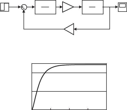
Now let us calculate the response of the armature-controlled DC motor as an
example. This is very easy to do by creating a Simulink model in Matlab, setting the
parameters, applying a step input, and plotting the0 response. Excellent tutorials for
learning how to use and apply Matlab and Simulink can be found at Internet Links
11.5 and 11.6. In the block diagram model shown in Figure 11.5 , the electrical and
mechanical transfer functions have been separated. A unit step input of voltage is
applied, and the output angular velocity is plotted, as shown in Figure 11.6 .
Internet Lin
k
11.5Matlab and
Simulink tutorials
and learning
resources
11.6Control
tutorials for Matlab
and Simulink
Figure 11.4 Block diagram for the DC motor system (plant).
negative feedback loop
+
V(s)
V(s) – k
e
Ω(s)
k
e
Ω(s)
Ω(s)
1
Ls + R
1
Is + c
k
t
k
e
I
a
(s) k
t
I
a
(s)
alc80237_ch11_478-522.indd 486alc80237_ch11_478-522.indd 486 10/01/11 8:27 PM10/01/11 8:27 PM
Confirming Pages
11.3 Introduction to Control Theory 487
Figure 11.5 Simulink model block diagram.
Kt
Torque
Constant
Step
Scope
1
I.s+c
Motor
(Mechanical)
1
L.s+R
Motor
(Electrical)
Ke
Electrical
Constant
Figure 11.6 The angular velocity output for a step input voltage.
0.00
10.00
20.00
0.00 0.05 0.10 0.15 0.20
time
output step response
The output angular velocity takes time to respond to the step input and asymp-
totically reaches a final value due to the second-order nature of the characteristic
equation. This overdamped response is what we call the open-loop response of the
motor because no feedback has been added to the system (except for the existing
internal back emf). It is our objective with a feedback controller to alter the response
so that it meets design specifications such as faster rise time, some limited overshoot,
and no oscillation.
11.3.3 Feedback Control of a DC Motor
In order to control the motor more effectively, we must add a sensor to monitor the
output (in this case, a tachometer to measure speed), feed back the output and com-
pare it to the desired speed input, and apply a control algorithm to the resulting error
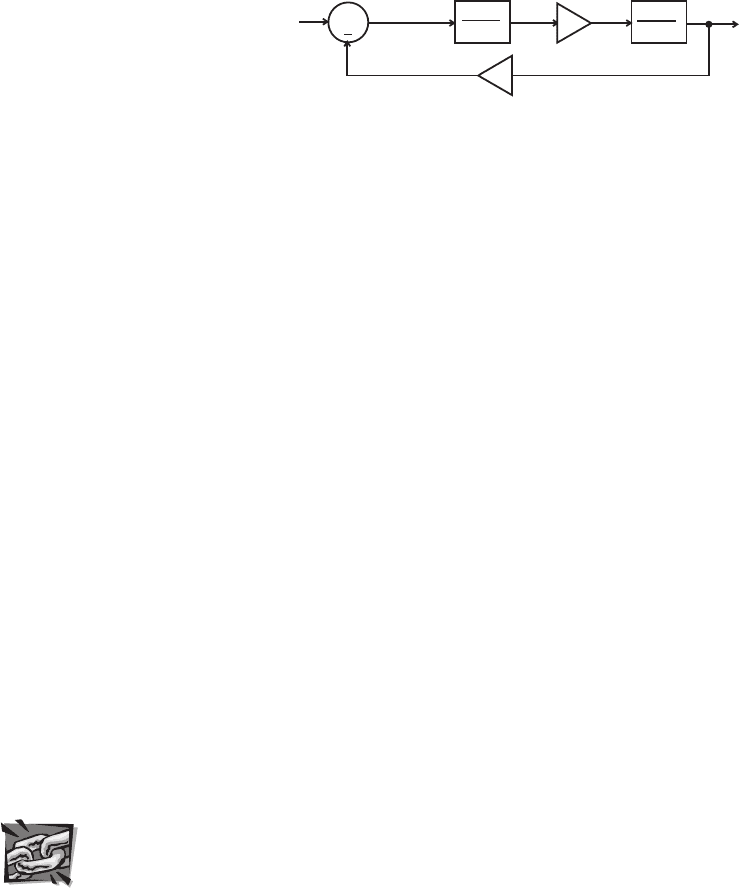
signal to improve the output response. Figure 11.7 shows a feedback control system
in block diagram form. The input is the desired motor speed, and the output is the
actual motor speed (e.g., as measured by a tachometer). The error signal is the differ-
ence between these signals:
error signal = input – output (11.8)
The controller changes its command signal (e.g., the motor voltage) to the system or
plant (e.g., the motor) in response to the error signal.
There is some art and some engineering involved in designing a controller for a
mechatronics system. The general steps for designing a controller include:
alc80237_ch11_478-522.indd 487alc80237_ch11_478-522.indd 487 10/01/11 8:27 PM10/01/11 8:27 PM

Confirming Pages
488 CHAPTER 11 Mechatronic Systems—Control Architectures and Case Studies
1 . Choose a control action. We will describe that process in the example; however,
generally, you start with a proportional control action, where the adjustment
is made to the input in proportion to the size of the error signal. Then, integral
and differential control actions, which are in proportion to the integral and
derivative of the error signal, can be added to help better achieve the desired
output specifications.
2 . Check to see that the closed-loop system is stable by identifying the pole loca-
tions on the complex s-plane. Any poles on the right-hand side (with a positive
real part) represent system instability.
3 . Make sure the steady-state response meets design specifications.
4 . Make sure the transient response meets design specifications.
5 . Check the overall performance of the mechatronic system through testing with
various inputs.
General controllers can take many forms but a majority of industrial applica-
tions use PID or proportional-integral-derivative controllers. The mathematical form
of a PID controller, where the error signal is expressed as e ( t ), is as follows:
command signal K
p
et() K
d
d
dt
---- -
et() K
i
et() td
∫
++=
(11.9)
where K
p
is referred to as the proportional gain, K
d
is the derivative gain, and K
i
is the
integral gain. Proportional control is the most intuitive because the control signal is
proportional to the error. The larger the error is, the larger the corrective action will
be. A large proportional gain creates a fast response, but it can lead to overshoot and
oscillation, especially if the system has little damping. Derivative gain responds to
the rate of change of the error signal. This allows the controller to anticipate changes
in response of the system, which can result in less overshoot and damped oscillation.
Integral gain helps eliminate steady-state error by summing up errors over time. The
longer the error stays on one side of the desired set point, the larger the corrective
action becomes as a result of integral gain. Video Demo 11.4 describes and demon-
strates the effect of each of the three control actions, as applied to position control of
a DC servo motor system.
The choice of the gain parameters in a PID controller is a significant part of
the design, and there are various analytical and empirical methods that can help one
choose the gains. The control design can be specified in terms of important criteria
such as settling time, overshoot, steady-state error, and rise time (see Figure 4.18
in Chapter 4 for more information). Please refer to a controls book (e.g., Ogata or
Video Demo
11.4PID
control of the
step response
of a mechanical
system
Figure 11.7 General feedback control system.
input
+
error
signal
command
signal
output
feedback loop
controller
system
(plant)
alc80237_ch11_478-522.indd 488alc80237_ch11_478-522.indd 488 10/01/11 8:27 PM10/01/11 8:27 PM
Confirming Pages
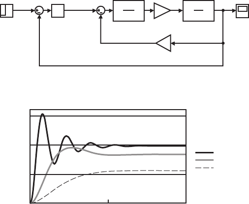
Figure 11.8 Simulink model of an example motor with a PID controller.
Kt
Torque
Constant
Step
Scope
PID
PID Controller
1
I.s+c
Motor
(Mechanical)
1
L.s+R
Motor
(Electrical)
Ke
Electrical
Constant
Figure 11.9 The effects of various proportional gains.
0.00
0.50
1.00
1.50
0.00 0.05 0.10
high K
p
medium K
p
low K
p
step response
time
11.3 Introduction to Control Theory 489
Palm in the bibliography) if you want to explore some of the analytical methods for
controller design.
An alternative to model-based analytical design is to interactively adjust
the PID gains via simulation. We will illustrate this method with the example of
speed control of an armature-controlled DC motor. The complete Simulink model,
including the motor model along with a PID feedback controller, is shown in
Figure 11.8 . The input is a step change in speed. The proportional, derivative, and
integral gains of the PID controller are easily adjusted in the Simulink software,
and the resulting output step response can be calculated and displayed almost
instantaneously. This allows the user to test various gain combinations quickly
during design iterations.
A good approach for varying the PID gains during design iterations in simula-
tion is to first gradually increase the proportional gain ( K
p
) until the rise time is fast
enough without too much overshoot and oscillation. Figure 11.9 shows the resulting
step responses for various proportional gain values. With low gains, the response is
slow, and there is significant steady-state error (i.e., the final value is not very close
to the desired final speed of 1.0). With a large proportional gain, the response is fast,
but there is significant overshoot and oscillation in the response.
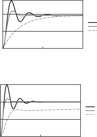
After adjusting the proportional gain, derivative gain can be added to limit the
overshoot and oscillation. Sometimes the proportional gain will need to be decreased
as more derivative gain is added to limit the overall gain of the system. Figure 11.10
shows the resulting step responses for various derivative gain values. With a low
alc80237_ch11_478-522.indd 489alc80237_ch11_478-522.indd 489 10/01/11 8:27 PM10/01/11 8:27 PM
Confirming Pages
Figure 11.11 The effects of various integral gains.
0.00
0.50
1.00
1.50
0.00 0.05 0.10
high K
p
and K
i
medium gains
low K
p
and K
i
step response
time
Figure 11.10 The effects of various derivative gains.
0.00
0.50
step response
1.00
0.00 0.05
time
0.10
low K
d
medium K
d
high K
d
490 CHAPTER 11 Mechatronic Systems—Control Architectures and Case Studies
gain, the overshoot and oscillation are still present. With very high derivative gain,
there is no overshoot or oscillation, but the response is very sluggish.
For most systems, with just proportional and derivative gains, the output response
will exhibit a steady-state error in the step response (i.e., the output doesn’t quite
reach the desired level). For the motor speed control example (see Figure 11.10 ), the
reason for this is clear. The command signal to the motor (see Figure 11.7 ) must be
nonzero to maintain a constant speed in steady state. Because the command signal
is a function of the error signal, with just proportional control (note that the derivate
term will be zero in steady state) there must be a nonzero error signal for the control-
ler to output a command signal to the motor to keep it turning. Integral gain allows
the controller to overcome this limitation and drive the error to zero. The integral
term sums the error over time and adds a larger correction to the command signal the
longer an error persists. Figure 11.11 shows the resulting step responses for various
integral gain values. For a high gain, the error dissipates very quickly, but overshoot
will be larger than if there was no integral gain. With a low integral gain, the error
diminishes slowly, but it does eventually dissipate to zero. The medium gains curve
exhibits a very good step response. There is very little overshoot and almost no oscil-
lation, and the output settles quickly with no steady-state error.
alc80237_ch11_478-522.indd 490alc80237_ch11_478-522.indd 490 10/01/11 8:27 PM10/01/11 8:27 PM
