Astakhov V. Tribology of Metal Cutting
Подождите немного. Документ загружается.

Generalized Model of Chip Formation 37
d
e
a
b
c
P
R
1
y
1
g
1
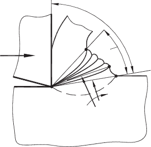
Fig. 1.24. Model of chip formation when seizure occurs at the tool–chip interface (after
Astakhov [78]).
deformation zone and surface ad separates this zone from the undeformed layer being
removed (the boundary of plastic and elastic zones in the work material). Boundaries
ac and ad are located by the angle ψ
1
relative to each other. As the tool progresses
in the cut, the material in the wedge-shaped zone acd are compressed, deformed and
thus squeezed in the direction of free boundary cd. When the load from the cutting
tool increases further, deformed plastic zone acd in front of the tool expands. As a
result, the angle ψ
1
increases. This increase can take place only due to the rotation of
the boundary ad in the clockwise direction, as the plastic deformation cannot progress
in the direction of boundary ac because the formed chip is already severely deformed
compared to the rest of the work material. Finally, rotating boundary ad takes its limiting
position ae, and the final configuration of deformed plastic zone ace is formed. As such,
gradually increasing the angle γ
1
up to 90
◦
, leads to a change in the mode of deformation
from the compression-type to the shear-type. When γ
1
= 90
◦
, fracture and thus sliding
of the partially formed chip takes place along the boundary ae. At the instant preceding
this fracture, the resistance to the tool penetration is at its maximum and the direction
of the reaction R
1
(from the elastically deformed part of layer being removed) becomes
parallel to the tool rake face while the normal pressure at the tool–chip interface becomes
insignificant. As a result, force R
1
shears the chip and deposit ace along the tool rake
face. The region in the vicinity of the cutting edge becomes clear and the sliding of the
chip over the tool rake face resumes until a new cycle of seizure and deposit formation
occurs.
Figure 1.25(a) presents system considerations of the model shown in Fig. 1.24. In this
figure, Phase 1 shows the instant when the sliding plane forms in the direction of the
maximum combined stress. When the chip slides over the tool rake face, the contact
length is heated up mainly due to chip deformation and friction. As the contact tem-
perature at the tool–chip interface grows, adhesion between the tool rake face and the
chip along the tool–chip interface increases as the materials of the chip fills even the
smallest roughness on the contact surface. In effect, the adhesion force at the tool–chip
interface increases. When the contact temperature reaches a certain level (for given work
38 Tribology of Metal Cutting
1
2
3
4
(a)
a
R
1
g
1
q
r−av
q
r−av
(b)
Time
(c)
(d)
P
P
c
d
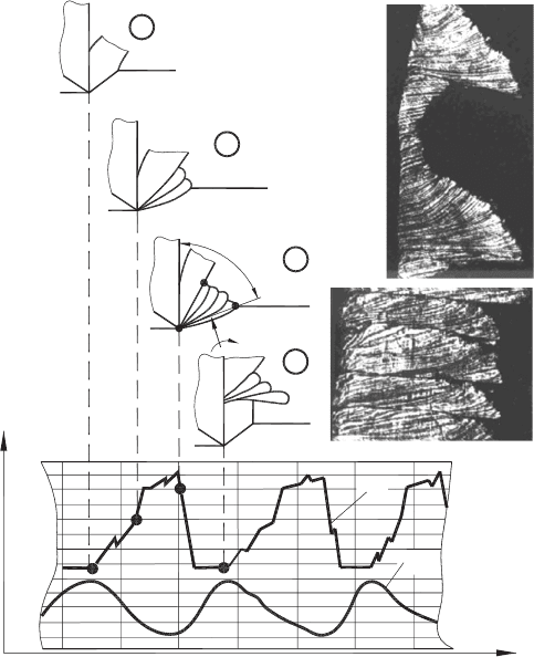
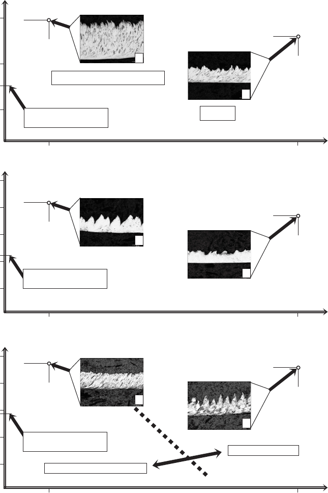
Fig. 1.25. System consideration of chip formation under conditions of seizure: (a) phases in chip
formation, (b) corresponding variations of the cutting force and temperature, (c) micrograph of the
continuous fragmentary humpbacked chip (×50) and (d) the continuous fragmentary humpbacked
chip formed when no stage of free sliding occurs at the tool–chip interface (×50).
and tool materials), the force required for chip sliding becomes greater than that of the
plastic deformation of a part of the layer being removed ahead of the tool. As such,
the chip and the tool are interlocked to such an extent that “normal” sliding cannot
occur. The interlocked part of the tool–chip contact changes the “normal” chip forma-
tion process causing an increase in the resistance to tool penetration. As a result, the
cutting force increases leading to an increase in the dimensions of the plastic zone in
front of the tool (Phase 2). In turn, the increase in size of the plastic zone leads to the
formation of a growing deposit on the interlocked part (Phase 3). Here, zone acd is the
current plastic zone formed after the chip sliding over the tool face ceases due to seizure.
Its boundary ac separates the plastic zone and the motionless chip while its boundary ad
separates this zone from the undeformed layer being removed. As the tool progresses in
the cut, the material in the plastic zone acd is compressed and squeezed in the direction
of its only free surface cd so that zone acd expands. As the chip is motionless and has
already been severely deformed, the plastic zone expands into the workpiece. During this
Generalized Model of Chip Formation 39
transformation, the angle γ
1
gradually increases up to 90
◦
that, in turn, leads to a change
in the deformation mode of the grooving deposit from the compression-type to the shear-
type. When γ
1
approaches 90
◦
, reaction force R
1
(from the elastically deformed part of
layer being removed) changes its direction to become parallel to the tool rake face
(Fig. 1.25(a), Phase 3). When the penetration force P reaches a certain limit, reaction
force R
1
becomes great enough to shear the whole deposit along the tool–chip interface.
Once the deposit has been sheared off, the “normal” chip formation takes place until the
contact temperature becomes high enough to start the formation of a new deposit.
To verify the model discussed experimentally, a cutting experiment was carried out.
A low carbon, low alloy steel (0.12% C, 1% Cr, 1% Mn, 1% Ti) was machined at a
cutting speed of 70 m/min, feed of 0.14 mm/rev, depth of cut of 2.0 mm with a M30
tool having the rake angle of −8
◦
. The penetration force P and the temperature at the
tool–chip interface were measured. Variations in the tool–chip contact temperature θ
r−av
and in the penetration force P were recorded simultaneously. Figure 1.25(b) presents
a sample of the results obtained. As shown, the penetration force increases during the
period of time of deposit formation while the contact temperature decreases because
there is no relative tool–chip sliding within this period.
The chip formed according to the model described is referred to as the continuous frag-
mentary humpbacked chip and its basic appearance is shown in Fig. 1.25(c), where the
zones of normal sliding and those of deposit formation can be clearly observed. This
chip cannot be regarded as continuous because its structure includes chip fragments
and their connectors although the distance between successive connectors is very small.
Figure 1.25(d) shows an extreme case of this type of the chip where no stage of free
sliding occurs at the tool–chip interface. The structure of this chip consists of series of
deposits following one another. As described, this chip formation process has a periodic
or almost periodic nature. As a result, the thickness of the chip formed almost shows
periodic variations when the chip formation conditions repeat themselves. Experience
shows that the appearance of the continuous fragmentary humpbacked chip may vary
significantly, although the mechanism of its formation is still the same.
An emergency situation can occur in this type of cutting when the adhesion forces at
the tool–chip interface are so high that the chip–tool contact cannot be separated by
the growing cutting force. As a result, the chip cannot slide over the tool face and the
chip formation process becomes impossible. Moreover, when the growing cutting force
reaches a certain limit, tool breakage is unavoidable. As such, the weakest components
of the tool will be deformed and/or fractured.
1.5.5 Model of chip formation for cutting with a high positive rake angle
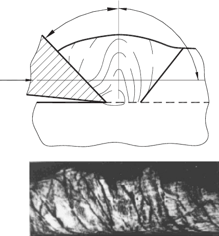
Figure 1.26(a) shows a model of chip formation for cutting a ductile work material with
the cutting tool having a high rake angle. As such, the rake angle may reach 30–45
◦
.
The reduction in the amount of plastic deformation with increasing rake angle eventually
leads to the condition where the angle θ
γ
between the plane of maximum shear-stress and
the direction of the compressive force P, approaches 90
◦
. Such a representation allows
one to compare the compression of the work material by the tool face with the pressing
40 Tribology of Metal Cutting
P
C
M
L
0
0.2
0.4
0.7
1
2
0.2
s
xy
(GPa)
D
q
g
g
(a)
(b)
Fig. 1.26. (a) A model for cutting with a high rake angle and (b) the chip structure obtained in
this process (after Astakhov [78]).
of a wedge-shaped workpiece between a pair of flat plates inclined with a small angle
relative to each other. In cutting, the tool rake face plays the role of one of the plates,
while the layer being removed where the plastic deformation has not yet occurred (the
conditional boundary between the plastic and elastic zone is shown in Fig. 1.26(a) as line
ML) plays the role of another plate. Under such conditions, the main part of the work
material flows in the direction of the “thick” part of the wedge-shaped plastic deformation
zone CMLD; the internal layers flow much more intensively than the external layers; and
the deformation rate in the “thin” part of deformation zone CMLD is much higher than
that in the “thick” part. To support this statement, the stress distribution in this zone is
shown by isolines obtained using a FEM simulation.
Foregoing considerations of cutting with high rake angles lead to the conclusion that
if the interaction of metal cutting system components is as shown in Fig. 1.26(a), the
work material fractures only along the line separating the workpiece and the layer being
removed so there are no other sliding planes formed in the chip. As a result, a special
chip type referred to as the continuous uniform-strength chip with wedge-shaped texture
is formed.
To verify this model, a number of cutting tests have been carried out. Figure 1.26(b)
shows a micrograph of the structure of the chip obtained in a turning cutting test con-
ducted under the following conditions: cutting speed ν = 120 m/min, depth of cut
d = 2 mm, feed f = 0.15 mm/rev, work material AISI steel 1015 with the initial
hardness 150 HV, rake angle γ
n
= 40
◦
, tool material P20, and no coolant was used.
The wedge-shaped fragments in the chip texture can be clearly seen in the micrograph
Generalized Model of Chip Formation 41
(Fig. 1.26(b)) where a higher strain is observed at the “thin” part of grains. To verify
this, a microhardness scanning test was carried out. It was found that the average micro-
hardness of the “thick” parts is 188 HV while that of the “thin” parts is 320 HV which
is in full agreement with the results of FEM analysis shown in Fig. 1.26(a) by isobars of
shear stress component σ
xy
(GPa).
1.5.6 Generalization
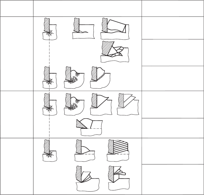
The above-discussed models allow us to propose a generalized model for chip formation
shown in Fig. 1.27. The model includes three basic regions, A, B and C, which correspond
to the properties of the work material.
Region A in this model generalizes models and chip structures obtained in the machining
of brittle materials. An analysis of these models shows that while cutting the brittle
Brittle
Ductile
Highly
Ductile
A
B
C
Work
Material
Model of Chip Formation
Chip
Structure
Separate almost rectangular
chip fragments -
the regularly broken chip
Irregularly shaped fragments
of work material and dust -
the irregularly broken chip
Regularly shaped separate
fragments with some plastic
deformation -
deformed fragmentary chip
Continuous fragmentary chip
with easy-to-distinguish
elements and connectors
Continuous chip
having practically uniform
strength along its length
Continuous fragmentary chip
with difficult-to-distinguish
elements and connectors
Unstable chip having variable
thickness along its length -
the continuous fragmentary
humpbacked chip
Fig. 1.27. Generalized model of chip formation.
42 Tribology of Metal Cutting
work materials, the chip shape is still a controllable parameter. When compression and
bending act together, much less energy has to be supplied to the machining zone and better
working conditions (at least the absence of dust) may be achieved. The tool geometry
plays an important role here. If selected properly, the chip formed has the appearance
of separate, almost rectangular elements and, therefore, is referred to as the regularly
broken chip.
As one might argue, however, a positive rake angle is not very practical in cutting cast
irons and similar brittle work materials due to the possible presence of significant amount
of hard inclusions. In such a case, a normal grade of tungsten carbide, as a tool material,
cannot withstand peak bending loads. As a result, practically all recommendations for
the tool geometry are the same suggesting a high negative rake angle that unavoidably
leads to the second model in Region A (Fig. 1.27). The chip formed consists of irregular-
shaped fragments of work material and dust, therefore, is referred to as the irregularly
broken chip. To overcome this barrier and to shift from the irregularly broken to the
regularly broken chip type, one should use positive rake angle when feasible. Modern
submicrograin carbides possess sufficient fracture toughness to withstand the discussed
inclusions successfully. The same logic is now applicable to high-speed machining of
high-silicon aluminum alloys widely used in the automotive industry. For many years,
polycrystalline diamond (PSD) brazed and indexable cutting inserts were used for this
purpose with negative rake angles. With the recent development of ultramicrograin PCDs
and advanced tool materials, cutting tool companies (for example, Kyocera, SP3, Mapal)
began to offer PCD insert with high positive (up to 10
◦
) rake angles that significantly
improve machining (tool life, machined surface integrity, reduce the cutting force, etc.)
of such alloys. Unfortunately, the recommendations for suitable tool geometries do not
reflect the great advances made in the last 5–10 years in the properties of tool materials
and coatings.
The last model in Region A is a kind of transitional model applicable to technically brittle
materials. As discussed above, some plastic deformation of the layer being removed is
allowed before a fragment of this layer separates from the workpiece.
Region B of the model shown in Fig. 1.27 covers two basic chip structures found in the
machining of most engineering materials. The chip formed according to the first model
in this region is referred to as the continuous fragmentary chip. As discussed, it is charac-
terized by non-uniform strength along its length. The chip fragments and their connectors
can be clearly distinguished on a micrograph of the chip structure. The difference in the
appearance of the chip fragments and connectors increases significantly with the cutting
speed. The chip formed according to the second model in this region is referred to as the
continuous chip. The major characteristics of its structure and properties were discussed
above. Additionally, it is necessary to point out that this chip is characterized by the
maximum (compared to the other chip structures) ratio “chip hardness/hardness of the
original work material” and by excessive length of the tool–chip interface.
Region C of the model shown in Fig. 1.27 represents two basic cases in the cutting
of highly ductile work materials. The first model in this region is basically the same
as the first model of Region B. However, great toughness of highly ductile materials
results in greater chip deformation and, as discussed above, the distance between the two
successive fragments becomes much smaller than that in the cutting of ductile materials.

Generalized Model of Chip Formation 43
The chip formed is referred to as the continuous fragmentary chip with difficult-to-
distinguish elements and their connectors. The second model of Region C of Fig. 1.27
represents unstable chip formation. The instability occurs mainly due to the periodic
seizure at the tool–chip interface. The chip formed under these conditions is referred
to as the continuous fragmentary humpback chip. This type of chip is common in the
machining of aerospace materials such as chromium- and/or high nickel-based alloys.
The models of chip formation presented in the generalized model shown in Fig. 1.27 can
be referred to as basic. The appearance of the chip may vary significantly depending on
the tool geometry, machining regime, contact conditions at the tool–chip interface and
other factors involved in chip formation.
1.6 Influence of Cutting Speed
So far, the models of chip formation process are considered irrespective of the cutting
speed, which actually has a marked influence on this process. The cutting speed affects
the chip formation process in two major ways. First, it changes the strain rate in the
deformation zone and thus affects the resistance of the work material and the thermal
energy generated in its deformation. Second, it affects the tool–chip relative speed and
the natural length of the tool–chip interface and thus affects the tribological conditions at
this interface. These two aspects are discussed in detail in Chapter 3. As a result, the chip
characteristics like the structure, appearance and physico-mechanical properties heavily
depend on the cutting speed.
Ekinovi
ˆ
c and coauthors [94] carried out a number of milling tests and studied the influ-
ence of cutting speed on the chip structure and appearance for different work materials
shown in Table 1.1. The test results are shown in Figs. 1.28(a)–(d).
Figure 1.28(a) shows the influence of cutting speed for work material 1 (low-carbon
steel). When this material is machined at a cutting speed of ν = 150 m/min, the classical
continuous fragmentary chip is produced (micrograph 1 in Figs. 1.28(a) and 1.29(a)).
Its average microhardness is much higher than that of the original work material that
reflects high plastic deformation of this chip. This conclusion is also fully supported
by relatively high (for this kind of work material) chip compression ratio, which is
Table 1.1. Work materials used in the test [94].
Metallurgical state
Chemical composition (%)
CSiMnP SCuCrNiMoV Al
Work material 1 –
annealed
0.17 0.27 0.41 0.019 0.013 0.31 0.12 0.08 0.01 – 0.053
Work material 2 –
austenized
0.04 0.45 1.55 0.028 0.035 0.53 18.26 8.80 0.63 0.08 0.017
Work material 3 –
annealed
0.62 1.00 0.59 0.017 0.004 0.26 5.46 0.23 1.21 0.46 0.028
Work material 4 –
tempered
44 Tribology of Metal Cutting
300
200
100
156
Microhardness, HVMicrohardness, HVMicrohardness, HV
150 1500
296 HV
Initial microhardness of
the work material
Initial microhardness of
the work material
Initial microhardness of
the work material
266 HV
420 HV
266 HV
470 HV
457 HV
(a) Work material 1
(b) Work material 2
500
400
300
200
100
221
500
400
300
200
100
282
High-Speed Region
Conventional Speed Region
1
2
3
4
5
6
f
seg
= 33.2 kHz
Cutting speed, v ( m/min)
150 1500
Cutting speed, v ( m/min)
(c) Work material 3
150 1500
Cutting speed, v ( m/min)
Chip compression ratio x = 3.4
x = 1.3
Fig. 1.28. Relations between the morphology of the chip and the cutting speed for different work
materials (Courtesy of Prof. S. Ekinovi
ˆ
c).
Generalized Model of Chip Formation 45
50 1500
800
700
600
500
400
629
150 300
7
8
9
10
(d) Work material 4
Microhardness, HV
660 HV
756 HV
742 HV
720 HV
f
seg
= 3.84 kHz
f
seg
= 15.6 kHz
f
seg
= 100.6 kHz
Fig. 1.28.—Continued.
(a) (b)
100 µm
100 µm
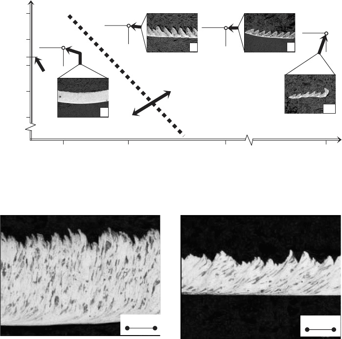
Fig. 1.29. Structures of the chip produced during machining of work material 1 at (a) ν =
150 m/min and (b) ν = 1500 m/min (Courtesy of Prof. S. Ekinovi
ˆ
c).
calculated as the ratio of the chip thickness (0.34 mm) and the uncut chip thickness
(0.10 mm), i.e. ξ = 0.34/0.10 = 3.4. Increasing the cutting speed to ν = 1500 m/min
does not change the type of chip structure produced (micrograph 2 in Figs. 1.28(b) and
1.29(b)). The reduction of chip plastic deformation occurred during the chip formation
results in smaller chip compression ratio (ξ = 1.3) and in lowering the average chip
microhardness.
Figure 1.28(b) shows the transformation of the chip structure with the cutting speed for
work material 2 (austenized stainless steel). The structure of the chip produced during
machining with ν = 150 m/min (micrograph 3 in Figs. 1.28(b) and 1.30(a)) also belongs
to the classical continuous fragmentary chip with saw-toothed (also referred to as serrated
46 Tribology of Metal Cutting
(a)
(b)
100 µm
100 µm
20 µm
Crack
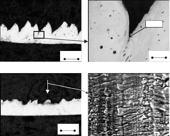
Fig. 1.30. Structures of the chip produced during machining of work material 2 at (a) ν =
150 m/min and (b) ν = 1500 m/min (Courtesy of Prof. S. Ekinovi
ˆ
c).
and fragmented) free surface. The cracks formed in the formation of this chip cannot
be completely “healed” by plastic deformation, so their tips can be clearly observed
at higher magnification (Fig. 1.30(a)). High average microhardness of this chip is a
consequence of high plastic deformation during its formation. Increasing the cutting
speed to ν = 1500 m/min does not change the type of chip structure produced, but
extensive heat generation in the formation of this chip causes its very high temperature
than annealing the deformed structure of this chip (micrograph 4 in Figs. 1.28(b) and
1.29(b)) and thus lowers its final microhardness. However, a SEM image of the free side
of this chip (Fig. 1.30(b)) reveals the presence of the fragments.
Figure 1.28(c) shows the transformation of the chip structure with the cutting speed
for work material 3 (high-carbon steel, annealed). The structure of the chip produced
during machining with cutting speed ν = 150 m/min (micrograph 5 in Figs. 1.28(c) and
1.30(a)) also belongs to the classical continuous fragmentary chip similar to that shown
in Fig. 1.29(a). However, high carbon content in this steel lowers its allowable plastic
deformation to fracture and thus the chip compression ratio for this chip is ξ = 1.7.
Increasing the cutting speed to ν = 1500 m/min changes the chip structure and thus its