Еврокод 3. Проектирование стальных конструкций. Часть 4-1. Бункеры
Подождите немного. Документ загружается.

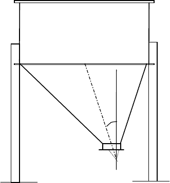
6.4.3 Unsymmetrical hopper
(1) If the axis of the hopper is not vertical, but inclined at an angle
ω
to the vertical (Fig. 6.4), the
increased meridional stresses on the steep side associated with this geometry should be evaluated, and
appropriate provision made to provide an adequate local meridional resistance.
6.4.4 Stiffened cones
(1) The stringer stiffeners should be adequately anchored at the top of the hopper.
(2) If the hopper cone is stiffened with meridional stiffeners, the effects of compatibility between
the wall plate and stringers should be included. The effect of the circumferential tension in the hopper
wall should be included in the assessment of the forces in the stringer stiffeners and the hopper wall
plate, as affected by the Poisson effect.
(3) The hopper plate joints should be proportioned to resist the increased tension arising from
compatibility.
(4) The connection between the stringer and hopper plate should be proportioned for the interaction
forces between them.
Figure 6.4: Unsymmetrical hopper with engaged columns in cylinder
6.4.5 Multi-segment cones
(1) If a hopper cone is composed of several segments with different slopes, the appropriate bulk
solids actions on each segment should be evaluated and included in the structural design.
(2) The local circumferential tensions or compressions at changes in hopper slope should be
evaluated, and adequate resistance provided to support them.
(3) The potential for severe local wear at such changes in hopper slope should be included in the
design.
6.5 Serviceability limit states
6.5.1 Basis
(1) If serviceability criteria are deemed necessary, specific limiting values for hoppers should be
agr
eed between the designer and the client.
ω
EN 1993-4-1:2007 (Е)
66
6.5.2 Vibration
(1) Provision should be made to ensure that the hopper is not subject to excessive vibration during
operation.
EN 1993-4-1:2007 (Е)
67

7 Design of circular conical roof structures
7.1 Basis
(1) The design of roof structures should take into consideration permanent, transient, imposed,
wind, snow, accidental and partial vacuum loads.
(2) The design should also take account of the possibility of upward forces on the roof due to
accidental overfilling or unexpected fluidisation of stored solids.
7.2 Distinctions between roof structural forms
7.2.1 Terminology
(1) A conical shell roof formed from rolled plates and without supporting beams or rings should be
termed a ‘shell roof’ or an ‘unsupported roof’.
(2) A conical roof in which sheeting is supported on beams or a grillage should be termed a
‘framed roof’ or a ‘supported roof’.
7.3 Resistance of circular conical silo roofs
7.3.1 Shell or unsupported roofs
(1) Shell roofs should be designed according to the requirements of EN 1993-1-6, but the following
provisions may be deemed to satisfy them for conical roofs with a diameter not greater than 5m and a
roof inclination to the horizontal
φ
not greater than 40°.
(2) The calculated surface von Mises equivalent stresses due to combined bending and membrane
action should everywhere be limited to the value:
f
e,Rd
= f
y
/
γ
M0
... (7.1)
where γ
M0
is obtained from 2.9.2.
(3) The critical buckling external pressure p
n,Rcr
for an isotropic conical roof should be calculated
as:
2,43
1,6
,
cos
2,65 (tan )
n Rcr
t
p E
r
φ
φ
= ⋅
... (7.2)
where:
r is the outer radius of the roof;
t is the smallest shell plate thickness;
φ
is the slope of the cone to the horizontal.
(4) The design buckling external pressure should be determined as:
p
n,Rd
=
α
p
p
n,Rcr
/
γ
M1
... (7.3)
in which
γ
M1
is obtained from 2.9.2.
NOTE: The National Annex may choose the value of
α
p
. The value
α
p
= 0,20 is recommended.
EN 1993-4-1:2007 (Е)
68
(5) The design peak external pressure on the roof arising from the actions defined in 7.1 should
satisfy the condition:
p
n,Ed
≤ p
n,Rd
... (7.4)
7.3.2 Framed or supported roofs
(1) Framed or supported roofs, where the roof sheeting is supported on beams or a grillage should
be designed according to the provisions of EN 1993-4-2 (Tanks).
7.3.3 Eaves junction (roof to shell junction)
(1) The roof to shell junction, and the ring stiffener at this junction should be designed according to
the provisions of EN 1993-4-2 (Tanks).
EN 1993-4-1:2007 (Е)
69
8 Design of transition junctions and supporting ring girders
8.1 Basis
8.1.1 General
(1) A steel transition ring or ring girder should be so proportioned that the basic design
requirements for the ultimate limit state given in section 2 are satisfied.
(2) The safety assessment of the ring should be carried out using the provisions of EN 1993-1-6,
except where the provisions of this Standard are deemed to satisfy them.
(3) For silos in Consequence Class 1, the cyclic plasticity and fatigue limit states may be ignored,
provided that the following conditions are met.
8.1.2 Ring design
(1) The ring or ring girder should be checked for:
− resistance to plastic limit under circumferential compression;
− resistance to buckling under circumferential compression;
− resistance to local yielding under tension or compression stresses;
− resistance to local failure above supports;
− resistance to torsion;
− resistance of joints (connections).
(2) The ring girder should satisfy the provisions of EN 1993-1-6, except where 8.2 to 8.5 provide
conditions that are deemed to satisfy the provisions of that standard.
(3) For silos in Consequence Class 1, the cyclic plasticity and fatigue limit states may be ignored.
8.1.3 Terminology
(1) A ring whose purpose is only to provide resistance to radial components of forces from the
hopper should be termed a ‘transition ring’.
(2) A ring whose purpose is to provide redistribution of vertical forces between different
components (e.g. the cylinder wall and discrete supports), should be termed a ‘ring girder’.
(3) The point of intersection between the middle surface of the hopper plate and the middle surface
of the cylindrical shell wall at the transition junction, termed the ‘joint centre’, should be used as the
reference point in limit state verifications.
(4) A silo with no identified ring at the transition (see figure 8.1) has an effective ring formed from
adjacent shell segments and should be termed a ‘natural ring’.
(5) An annular plate placed at the transition junction should be termed an ‘annular plate ring’, see
figure 8.1.
(6) A hot rolled steel section, used as a ring stiffener at the transition should be termed a ‘rolled
section ring’.
(7) A rolled steel section rolled around the silo circumference and used to support the shell beneath
the transition should be termed a ‘rolled ring girder’.
EN 1993-4-1:2007 (Е)
70
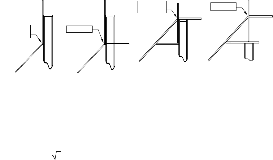
(8) A section built up from steel plates with cylindrical and annular plate forms should be termed a
‘fabricated ring girder’, see figure 8.1.
8.1.4 Modelling of the junction
(1) In hand calculations, the junction should be represented by cylindrical and conical shell
segments and annular plates only.
(2) Where the silo is uniformly supported, the circumferential stresses in the annular plates of the
junction may be assumed to be uniform in each plate.
(3) Where the silo is supported on discrete supports or columns, the circumferential stresses in the
junction plates should be taken to vary radially in each plate as a consequence of warping stresses.
Cone/cylinder
junction
Joint centre
Cone/cylinder
junction
Joint centre
Natural ring with
engaged column
Annular plate ring with
engaged column
Triangular box with
column engaged to
skirt
Triangular box with
concentric column
beneath skirt
Figure 8.1: Example ring forms
8.1.5 Limitations on ring placement
(1) The vertical eccentricity of any annular plate or ring from the transition joint centre should not
be g
reater than 0,2 rt, where t is the thickness of the cylinder plate, unless a shell bending
calculation according to EN 1993-1-6 is carried out to check the effect of the eccentricity.
NOTE: This rule arises from the ineffectiveness of rings placed further than this from the junction, see
figure 8.2.
(2) The simplified rules in 8.2 apply only where this requirement is met.
8.2 Analysis of the junction
8.2.1 General
(1) For silos in Consequence Class 1, the transition junction may be analysed using simple
expressions and loadings from adjacent shell segments derived from membrane theory.
(2) Where a computer calculation of the transition junction is performed, it should satisfy the
requirements of EN 1993-1-6.
(3) Where a computer calculation is not used and the silo is uniformly supported, the analysis of
the junction may be undertaken using 8.2.2.
(4) Where a computer calculation is not used and the silo is supported on discrete supports or
columns, the analysis of the junction should be undertaken using 8.2.3.
EN 1993-4-1:2007 (Е)
71

r
r
t
t
e
e
λ
λ
=
=
2
2
,
,
4
4
4
4
r
r
t
t
r
r
/
/
t
t
=
=
5
5
0
0
0
0
T
/
/
t
t
c
c
=
2
2
b
b
/
/
T
T
=
=
1
1
0
0
t
t
h
/
/
t
t
c
=
=
1
1
β
=
4
5
5
°
°
s
s
t
t
r
r
e
e
s
s
s
s
i
i
n
n
h
h
o
o
p
p
p
p
e
e
r
r
s
s
t
t
r
r
e
e
s
s
s
s
i
i
n
n
s
s
k
k
i
i
r
r
t
t
s
s
t
t
r
r
e
e
s
s
s
s
i
i
n
n
a
a
n
n
n
n
u
u
l
l
a
a
r
r
p
p
l
l
a
a
t
t
e
e
r
r
i
i
n
n
g
g
c
c
i
i
r
r
c
c
u
u
m
m
f
f
e
e
r
r
e
e
n
n
t
t
i
i
a
a
l
l
s
s
t
t
r
r
e
e
s
s
s
s
r
r
a
a
t
t
i
i
o
o
σ
σ
m
m
θ
σ
σ
m
m
θ
θ
(
e
e
=
=
0
0)
4
4
3
2
2
1
1
0
0
.
.
2
2
0.
4
4
0
0
.
.
6
6
0.
8
8
1
1
.
.
0
0
1
1
.
.
2
2
0
0
d
d
i
i
m
m
e
e
n
n
s
s
i
i
o
o
n
n
l
l
e
e
s
s
s
s
e
e
c
c
c
c
e
e
n
n
t
t
r
r
i
i
c
c
i
i
t
t
y
y
e
e
/
/
λ
λ
Figure 8.2: Membrane stresses developed in a ring and adjacent shell when
the ring is eccentric
8.2.2 Uniformly supported transition junctions
(1) The effective section of the transition junction should be evaluated as follows: the shell
segments meeting at the joint centre should be separated into those above (Group A) and those below
(Group B), see figure 8.3 (a). All annular plate segments at the level of the joint centre should be
initially ignored. Where a vertical leg is attached to the annular plate at a different radial coordinate
from the joint centre, it should be treated as a shell segment in the same manner as the others, see
figure 8.3.
A
B
t
c
t
t
s
s
t
h
h
t
eqA
=
=
t
c
c
t
t
e
q
B
=
=
t
t
s
s
2
2
+
+
t
t
h
2
2
A
A
n
n
n
n
u
u
l
l
a
a
r
r
p
p
l
l
a
a
t
t
e
e
l
l
l
es
l
l
ec
l
ll
l
eh
T
T
h
h
i
i
s
s
f
f
l
l
a
a
n
n
g
g
e
e
n
n
o
o
t
t
e
e
f
f
f
f
e
e
c
c
t
t
i
i
v
v
e
e
f
f
o
o
r
r
circ
u
u
m
mf
e
ere
n
n
t
tial
comp
r
ress
i
ion
a) Geometry b) Effective ring beam for
circumferential compression
Figure 8.3: Effective section of the cylinder / hopper / ring transition
(2) The equivalent thickness t
eqA
and t
eqB
of each group should be determined from:
EN 1993-4-1:2007 (Е)
72
2
eqA
A
t t
=
∑
... (8.1)
2
eqB
B
t t
=
∑
... (8.2)
(3) The ratio α of the thinner to the thicker equivalent plate group should be determined from:
( )
( )
eq thinner
eq thicker
t
t
α
= ... (8.3)
with:
(t
eq
)
thinner
= min(t
eqA
, t
eqB
) ... (8.4)
(t
eq
)
thicker
= max(t
eqA
, t
eqB
) ... (8.5)
(4) For the thinner of these two groups, the effective length of each shell segment should be
determined from:
l
e1
= 0,778
cos
rt
β
... (8.6)
where
β
is the angle between the shell centreline and the silo axis (cone apex half angle) for that
plate. The effective cross-sectional area of each shell segment should be determined from:
A
e1
=
l
e1
t ... (8.7)
For the thicker of these two groups, the effective length of each shell segment should be determined
from:
l
e2
= 0,389
2 3
[1 3 2 ]
cos
rt
α α
β
+ − ... (8.8)
For this group, the effective cross-sectional area of each shell segment should be determined from:
A
e2
=
l
e2
t ... (8.9)
EN 1993-4-1:2007 (Е)
73
(5) The effective cross-sectional area A
ep
of the annular plate joining into the junction at the joint
cent
re should be determined from:
1 0,8
p
ep
bt
A
b
r
=
+
... (8.10)
where:
r is the radius of the silo cylinder wall;
b is the radial width of the annular plate ring;
t
p
is the thickness of the annular plate ring.
(6)
The total effective area A
et
of the ring in developing circumferential compression should be
determined from:
all segments
1
et ep ei
i
A A A
=
= +
∑
... (8.11)
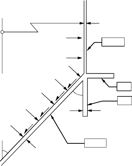
(7) Where the junction consists only of a cylinder, skirt and hopper (see figure 8.4), the total
effective area of the ring A
et
may be alternatively found from:
A
et
= A
ep
+ 0,778
++
2/3
s
2/3
h
2/3
c
cos
t
t
tr
β
ψ
... (8.12)
with:
ψ
= 0,5 (1 + 3α
2
− 2α
3
) ... (8.13)
2 2
c
s h
t
t t
α
=
+
... (8.14)
where:
r is the radius of the silo cylinder wall;
t
c
is the thickness of the cylinder;
t
s
is the thickness of the skirt;
t
h
is the thickness of the hopper;
A
ep
is the effective area of the annular plate ring.
EN 1993-4-1:2007 (Е)
74
r
t
t
c
c
p
n
n
c
c
p
n
n
h
h
C
C
y
y
l
lind
e
e
r
r
A
p
p
R
R
i
i
n
n
g
g
S
S
k
k
i
i
r
r
t
t
Ho
p
pp
e
e
r
r
t
t
s
s
t
t
h
β
β
β
β
µ
p
n
n
Figure 8.4: Notation for simple annular plate transition junction
(8) Where sections of more complex geometry are used at the transition junction, only ring plate
segments meeting the condition of 8.1.5 (1) should be deemed to be effective in the evaluation of the
junction.
(9) The design value of the effective circumferential compressive force N
θ,Ed
developed in the
junction should be determined from:
N
θ,Ed
= n
φh,
Ed
r sin
β
− p
nc
r
l
l
ec
− p
nh
(cos
β
−
µ
sin
β
) r
l
eh
... (8.15)
where (see figure 8.5):
r is the radius of the silo cylinder wall;
β
is the half angle of the hopper (at the top);
l
ec
is the effective length of the cylinder segment above the transition (see (4));
l
l
eh
is the effective length of the hopper segment (see (4));
n
φh,Ed
is the design value of the meridional tension per unit circumference at the top of
the hopper;
p
nc
is the mean local pressure on the effective length of the cylinder segment;
p
nh
is the mean pressure on the effective length of the hopper segment;
µ
is the hopper wall friction coefficient.
EN 1993-4-1:2007 (Е)
75