Hancock G.J., Murray Th.M., Ellifritt D.S. Cold-Formed Steel Structures to the AISI Specification
Подождите немного. Документ загружается.

The vertical impact load is 25% of an individual unit
load. Vertical impact loads equivalent to the unit load
factored by 1.25 should be used in the design of individual
beams and connectors.
11.3 METHODS OF STRUCTURAL ANALYSIS
11.3.1 Upright Frames
The RMI Speci®cation (Ref. 11.1) states that computations
for safe loads, stresses, de¯ections, and the like shall be
made in accordance with conventional methods of struc-
tural design as speci®ed in the latest edition of the AISI
Speci®cation for cold-formed steel components and struc-
tural systems and the latest edition of the AISC Speci®ca-
tion for hot-rolled steel components and systems except as
modi®ed or supplemented by the RMI Speci®cation. Where
adequate methods of design calculations are not available,
designs shall be based on test results.
In the ®rst-order method of analysis, the structure is
analyzed in its undeformed con®guration. The ®rst-order
bending moments are ampli®ed within the beam-column
interaction equations (see Section 8.2), using the buckling
load of the frame based on the appropriate effective
lengths. In the case of down-aisle stability, a value of
K
x
L
x
=L of 1.7 is suggested if a rational buckling analysis
is not performed. However, it is recommended that the
value of effective length be determined accurately, account-
ing for the joint ¯exibility and the restraint provided at the
column bases. Detailed equations are included in the
Commentary to the RMI Speci®cation in Section 6.3.1.1
(racks not braced against side sway) for the determination
of the G
A
and G
B
factors when calculating the effective
lengths using the AISI Speci®cation. Example 11.6 demon-
strates these calculations.
The in¯uence of the joint ¯exibility is best determined
experimentally using the portal test described in Section
Chapter 11
358
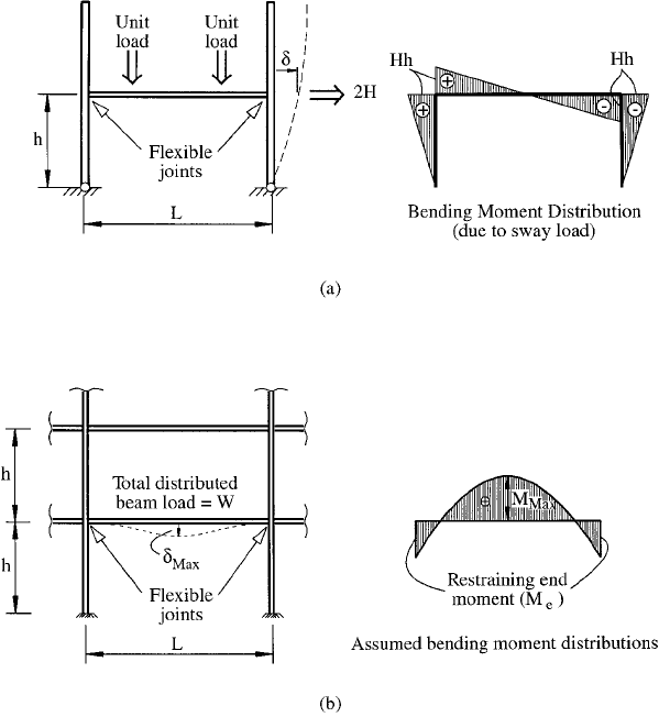
9.4.2 of the RMI Speci®cation. The portal test involves
determining the sway stiffness of a single frame as shown
in Figure 11.2a. The method for evaluation of the test
results is set out in the Commentary to the RMI Speci®ca-
tion in Section 9.4.2.3 to determine the spring constant (F)
relating the moment to the rotation of the ¯exible joints
shown in Figure 11.2a. The advantage of the portal test in
determining F is that the stiffness of the connection at one
end of the beam corresponds to joint opening, and the
FIGURE 11.2 In¯uence of ¯exible joints: (a) portal test; (b) beam
de¯ections and moments.
Steel Storage Racking
359

stiffness of the connection at the other end of the beam
corresponds to joint closing. The ®nal value of F is an
average of these two values, as it would be in practice.
The joint stiffness is determined with the appropriate unit
loads applied on the pallet beam as shown in Figure 11.2a
to ensure that the joints are measured in their loaded state.
11.3.2 Beams
In the design of pallet beams in steel storage racks, the end
®xity produces a situation where the beam can be regarded
as neither ®xed-ended nor pin-ended. It is important to
accurately account for the joint ¯exibility in the design of
beams since the beam de¯ections and the bending moment
distribution are highly dependent on the value of joint ¯ex-
ibility. If a very stiff joint is produced, the beam de¯ections
will be reduced. However, the resulting restraining moment
on the end of the beam may damage the joint. If a very
¯exible joint is used, the beam de¯ections may be excessive.
The de¯ected shape of a pallet beam and the assumed
bending moment distribution are shown in Figure 11.2b.
The restraining moment (M
e
) is a function of the joint
stiffness (F), which can be determined from either a canti-
lever test, as described in Section 9.4.1 of the RMI Speci-
®cation, or the pallet beam in upright frame assembly test,
as described in Section 9.3.2 of the RMI Speci®cation. The
resulting equations for the maximum bending moment
(M
max
) and central de¯ection (d
max
) are given by Eqs.
(11.2) and (11.3), which are based on the bending moment
distribution in Figure 11.2b.
M
max
WL
8
r
m
11:2a
r
m
1 ÿ
2FL
6EI
b
3FL
11:2b
where W total load on each beam
L span of beam
Chapter 11
360

F joint spring constant
E modulus of elasticity
I
b
beam moment of inertia about the bending axis
and column, respectively
d
max
d
ss
r
d
11:3a
d
ss
5WL
3
384EI
b
11:3b
r
d
1 ÿ
4FL
5FL 10EI
b
11:3c
Section 5.2 of the RMI Commentary recommends that the
maximum value of de¯ection at the center of the span not
exceed 1=180 of the span measured with respect to the ends
of the beam.
11.3.3 Stability of Truss-Braced Upright
Frames
To prevent tall and narrow truss-braced upright frames of
the type shown in Figure 11.1a from buckling in their own
plane, elastic critical loads (P
cr
) are speci®ed in Section 6.4
of the 1997 RMI Speci®cation. The elastic critical loads can
be used to compute an equivalent effective length for use in
the AISI Speci®cation for cold-formed members or the AISC
Speci®cation for hot-rolled members.
11.4 EFFECTS OF PERFORATIONS (SLOTS)
The uprights of steel storage racks usually contain perfora-
tions (slots) where pallet beams and bracing members are
connected into the uprights. These perforations can
produce signi®cant reductions in the bending and axial
capacity of the upright sections. The design rules for
¯exural members use the elastic section modulus of the
net section (S
x;net min
). The design rules for axially loaded
compression members use the minimum cross-sectional
Steel Storage Racking
361
area (A
net min
). Hence, it is necessary to determine these
properties for the upright sections.
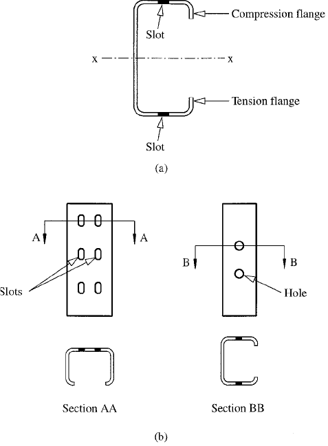
11.4.1 Section Modulus of Net Section
A perforated beam section in bending is shown in Figure
11.3a. The effect of the slot in the ¯anges is to reduce the
second moment of area and hence the section modulus
(S
x;net min
) of the net section. S
x;net min
is the minimum
value of the section modulus with the holes removed.
FIGURE 11.3 Perforated sections: (a) ¯exural member; (b) com-
pression member.
Chapter 11
362

A perforated compression member is shown in Figure
11.3b. The slots in the web are staggered so that they do not
coincide with the holes in the ¯anges. Consequently, when
a plane is passed through Section AA, a different net area
will be determined from the case where a plane is passed
through Section BB. The minimum net area (A
net min
) is the
lesser of these two values. If the slots and holes coincide,
the minimum net area must have both slots and holes
deducted from the total area.
11.4.2 Form Factor (Q)
The form factor (Q) allows for the effects of local buckling
and postbuckling on the stub column strength of the section
with perforations. The Q factor cannot be determined
theoretically, so a test procedure is described in Section
9.2 of the RMI Speci®cation. The value of Q is
Q
Ultimate compressive strength
of stub upright by test
F
y
A
net min
11:4
where F
y
actual yield stress of the upright material. The
value of Q allows for the interaction of local buckling with
the perforations, but does not allow for the reduced area
resulting from the perforations, since this has already been
accounted for by using A
net min
in the design equations, as
described in Section 11.5.
11.5 MEMBER DESIGN RULES
The member design rules for ¯exural and compression
members speci®ed in the 1996 AISI Speci®cation have
been modi®ed in the 1997 RMI Speci®cation to take account
of the perforations. The values of S
x;net min
and A
net min
are
used in conjunction with the design rules in the AISI
Speci®cation to produce moment and axial capacities.
Steel Storage Racking
363

11.5.1 Flexural Design Curves
The effective section modulus (S
e
) with the extreme compres-
sion or tension ®ber at F
y
and speci®ed in Section C3.1.1 of
the AISI Speci®cation for computing the nominal ¯exural
strength (M
n
) is modi®ed in the 1997 RMI Speci®cation to
S
e
0:5
Q
2
S
x;net min
11:5
The form factor Q is determined from a stub column test as
described in Section 11.4.2 and in Section 9.2 of the 1997
RMI Speci®cation.
The effective section modulus (S
c
) at the critical stress
(F
c
M
c
=Z
f
) in the extreme compression ®ber and speci®ed
in Section C3.1.2 of the AISI Speci®cation for computing
the nominal ¯exural strength (M
n
) is modi®ed in the 1997
RMI Speci®cation to
S
c
1 ÿ
1 ÿ Q
2
M
c
=S
f
F
y
!
Q
0
@
1
A
S
x;net min
11:6
In Eqs. (11.5) and (11.6), the effect of local buckling and the
interaction of local buckling with perforations are
accounted for by using the form factor Q derived from a
stub column test. As M
c
and F
c
decrease, S
c
approaches the
section modulus of the net section (S
x;net min
). As the value of
F
c
M
c
=S
f
approaches F
y
, S
c
approaches that given by Eq.
(11.5), where the effect of Q is essentially half what it would
be for a stub column since only one ¯ange is in compression,
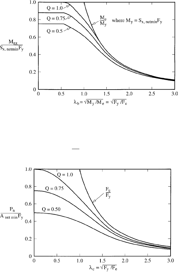
as shown in Figure 11.3a. The resulting design curves for
different values of Q are shown in Figure 11.4, where M
e
is
the elastic critical moment determined according to Section
C3.1.2 of the AISI Speci®cation.
11.5.2 Column Design Curves
The effective area (A
e
) at the buckling stress (F
n
) and
speci®ed in Section C4 of the AISI Speci®cation for comput-
ing the nominal axial strength (P
n
) is modi®ed in the 1997
Chapter 11
364
RMI Speci®cation (Ref. 11.1) to
A
e
1 ÿ1 ÿ Q
F
n
F
y
!
Q
0
@
1
A
A
net min
11:7
FIGURE 11.4 Rack Manufacturers Institute beam design curves.
FIGURE 11.5 Rack Manufacturers Institute column design
curves.
Steel Storage Racking
365

where Q is determined from a stub column test as described
in Section 11.4.2 and in Section 9.2 of the RMI Speci®ca-
tion. As the nominal buckling stress (F
n
) approaches the
yield stress, the effective area approaches QA
net min
. For
long columns with a low value of F
n
, the effective area
approaches A
net min
. The resulting design curves for differ-
ent values of Q are shown in Figure 11.5, where F
c
is the
elastic buckling stress determined according to Section C4
of the AISI Speci®cation.
11.6 EXAMPLE
Problem: Unbraced Pallet Rack
Calculate the design load in the uprights for the three-level
multibay rack in Figure 11.6b. The upright section is shown
in Figure 11.6a. The design example is the same frame and
section as in Problem 1, Part III of Ref. 11.2. Section
numbers refer to the speci®cation referenced in each
section (A to I).
Solution
A. Gross Section Properties
Rounded Corners [computed using THIN-WALL (Ref. 11.3)]
A
g
1:046 in:
2
I
xp
1:585 in:
4
I
yp
1:304 in:
4
J 0:00385 in:
4
C
w
3:952 in:
6
r
xg
1:232 in:
r
yg
1:118 in:
x
0
ÿ2:935 in:
y
0
0
S
xmin
I
xp
a
0
=2
1:057 in:
3
Chapter 11
366
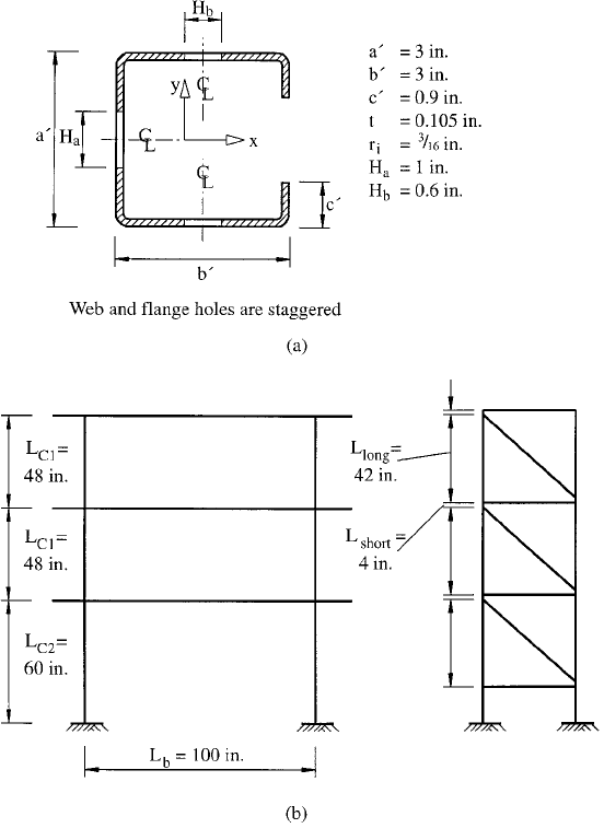
FIGURE 11.6 Unbraced storage rack example: (a) perforated
lipped channel; (b) frame geometry.
Steel Storage Racking
367