Inversin R. Allen Micro-hydropower Sourcebook
Подождите немного. Документ загружается.

0 1
tm
(contours at 1 m interds)
r
*D
Section AA
-. - -- __.
_ .
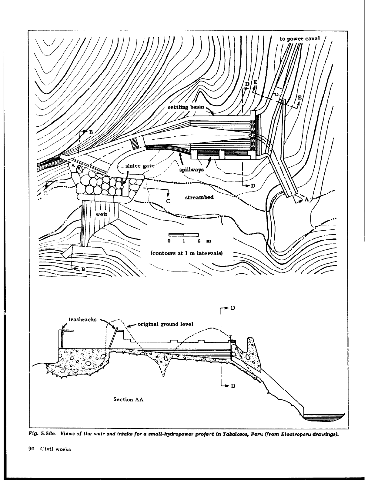
r-lg. 5.56a. views or the weir and
intake for a
small-hyiropowe~ project in
Tabdosos, Peni
Warn EZectrcqWu
dmv~ings).
90 Civil works
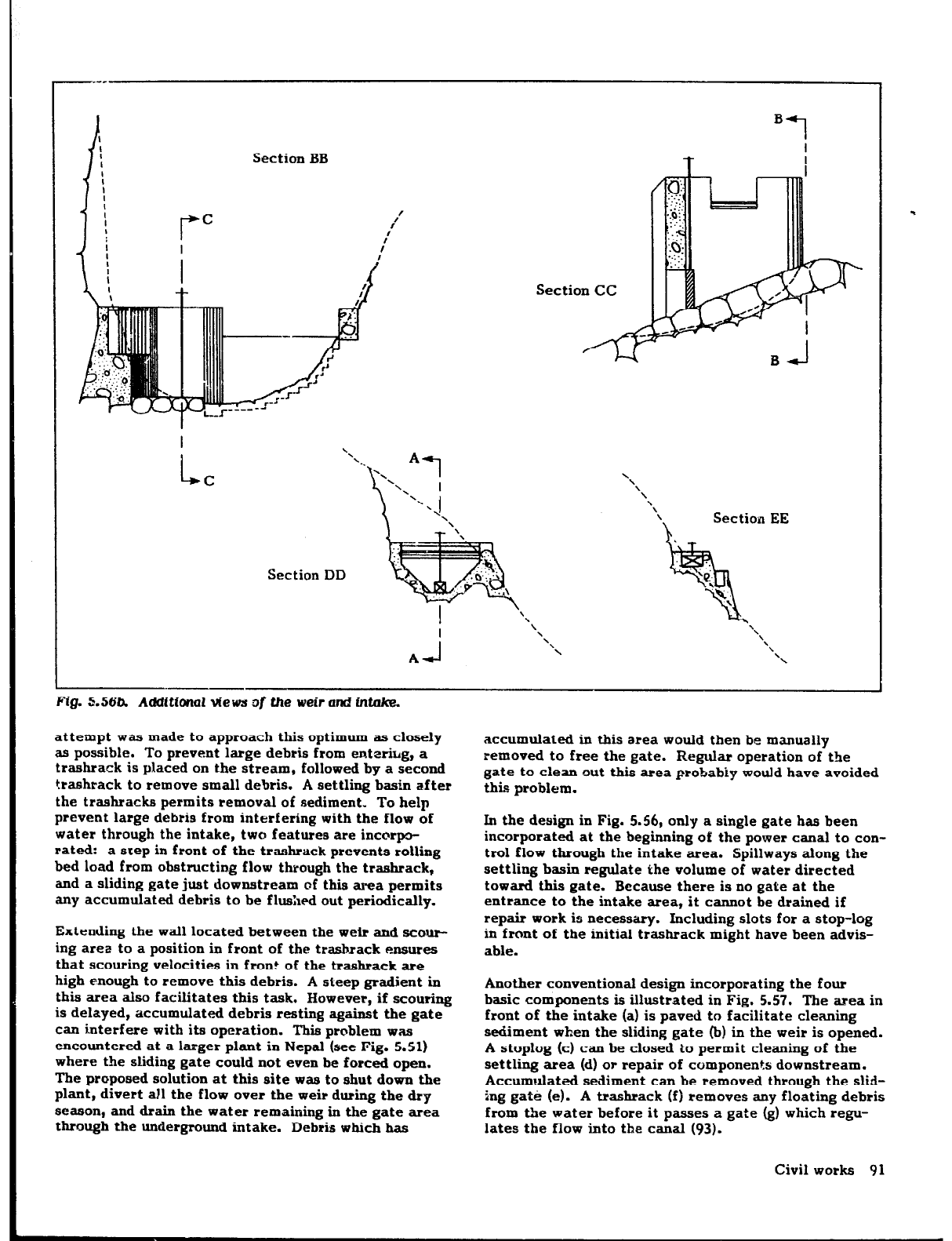
Section BB
Section CC
I
L
‘\
‘\
C
\
\
\
\
\
\
\
Section EE
Section DD
Fig. 5.56b. Additional views z)f the weir and intnke.
attempt was made to approach this optimum as closely
as possible. To prevent large debris from entetig, a
trashrack is placed on the stream, followed by a second
trashrack to remove small debris. A settling basin after
the trashracks permits removal of sediment. To help
prevent large debris from interfering with the flow of
water through the intake, two features are incotpo-
rated: a step in front of the trashrack prevents rolling
bed load from obstructing flow through the trashrack,
and a sliding gate just downstream of thii area permits
any accumulated debris to be flushed out periodically.
Extending the wall located between the weir and scour-
ing ares to a position in front of the trashrack erures
that scouring velocities in front of the trashrack are
high enough to remove this debris. A steep gradient in
this area also facilitates this task. However, if scouring
is delayed, accumulated debris testing against the gate
can interfere with its operation. This problem was
encountered at a larger plant in Nepal (see Fig. 5.51)
where the sliding gate could not even be forced open.
The proposed solution at this site was to shut down the
plant, divert all the flow
over
the weir during the dry
season, and drain the water remaining in the gate area
through the underground intake. Debris which has
accumulated in this area would then be manually
removed to free the gate. Regular operation of the
gate to clean out this area probably would have avoided
this problem.
In the design in Fig. 5.56, only a single gate has been
incorporated at the beginning of the power canal to con-
trol flow through the intake area. Spillways along the
settling basin regulate the volume of water directed
toward this gate. Because there is no gate at the
entrance to the intake area, it cannot be drained if
repair work is necessary. Including slots for a stop-log
in front of the initial trashrack might have been advis-
able.
Another conventional design incorporating the four
basic components is illustrated in Fig. 5.57. The area in
front of the intake (a) is paved to facilitate cleaning
sediment when the sliding gate (b) in the weir is opened.
A stoplog (c) can be closed to permit cleaning of the
settling area (d) or repair of components downstream.
Accumulated sediment can be removed through the slid-
ing gate (e). A trashrack
(f)
removes any floating debris
from the water before it passes a gate (g) which regu-
lates the flow into the canal (93).
Civil works 91
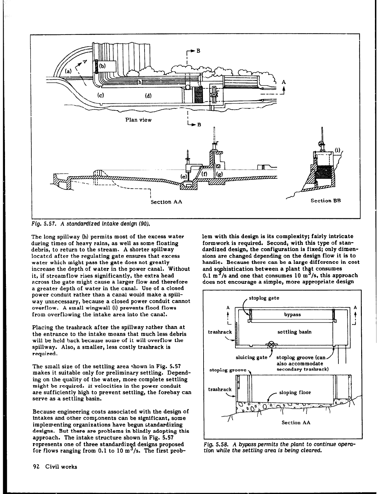
Plan view
n
I
Section AA
/I
Section BB
across the gate might cause a larger flow and therefore does not encourage a simple, more appropriate design
a greater depth of water in the canal. Use of a closed
power conduit rather than a canal would make a spill-
way unnecessary, because a closed power conduit cannot
/
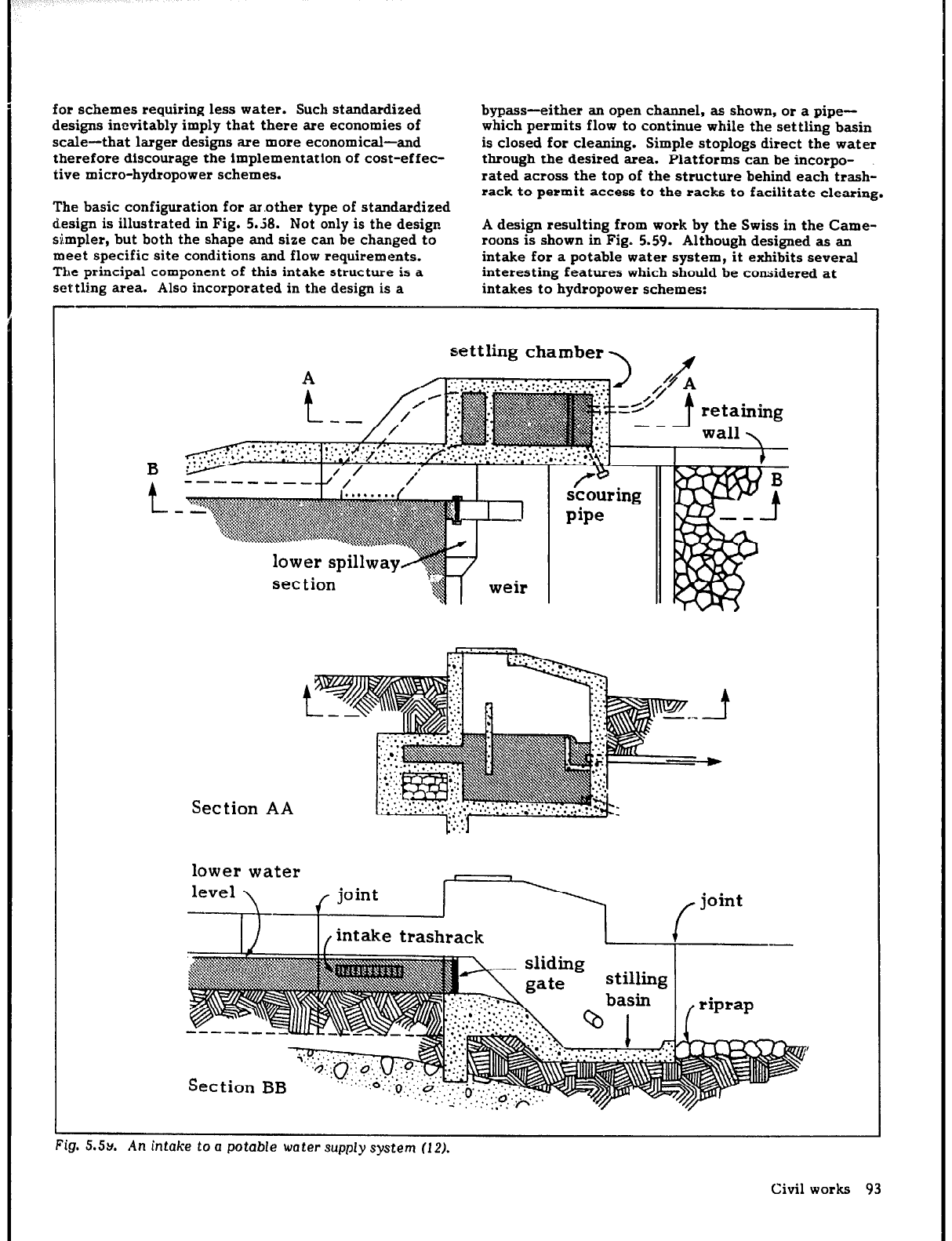
stoplog gate
overflow.
A small wingwall (i) prevents flood flows
A
A
from overflowing the intake area into the cana!.
t t
Placing the trashrack after the spillway rather than at
L
i
the entrance to the intake means that much less debris
trashrack
will be held back because some of it will overflow the
spillway. Also, a smaller, less costly trashrack is
requited.
+
/
?I I
sluicing gate
The small size of the settling area shown in Fig. 5.57
makes it suitable only for preliminary settling. Depend-
ing on the quality of the water, more complete settling
might be required. or velocities in the power conduit
are sufficiently high to prevent settling, the forebay can
serve as a settling basin.
stoplag groove,
stoplog groove (can/ 1 1
also accommodate
secondary trashrack)
mg. 5.57. A stancfamzeci IntaKe aesqp w).
The long spillway (h) permits most of the excess water
lem with this design is its complexity; fairly intricate
during times of heavy rains, as well as some floating
formwork is required. Second, with this type of stan-
debris, to return to the stream. A shorter spillway
dardized design, the configuration is fixed; only dimen-
located after the regulating gate ensures that excess sions are changed depending
on
the design flow it is to
water which might pass the gate does not greatly
handle. Because there can be a large difference in cost
increase the depth of water in the power canal. Without and s histication between a plant th t consumes
it, if streamflow rises significantly, the extra head
Y
0.1 m 1s and one that consumes 10 m
9
/s, this approach
Because engineering costs associated with the design of
intakes and other components can be significant, some
implementing organizations have begun standardizing
designs. But there are problems in blindly adopting this
approach. The intake structure shown in Fig. 5.57
Section AA
represents one
of
three standardiz
3
d designs proposed
for flows ranging from 0.1 to 10 m /s. The first prob-
Fig. 5.58. A bypass permits the plant to continue
OPM-
tion while
the
settling area is being
cleared.
92
Civil works
for schemes requiring less water. Such standardized
designs inevitably imply that there are economies of
scale-that larger designs are more economical-and
therefore discourage the implementation of cost-effec-
tive micro-hydropower schemes.
The basic configuration for ar.other type of standardized
design is illustrated in Fig. 5.58. Not only is the design
simpler, but both the shape and size can be changed to
meet specific site conditions and flow requirements.
The principal component of this intake structure is a
settling area. Also incorporated in the design is a
bypass-either an open channel, as shown, or a pipe-
which permits flow to continue while the settling basin
is closed for cleaning. Simple stoplogs direct the water
through the desired area. Platforms can be incorpo-
rated across the top of the structure behind each trash-
rack to permit access to the racks to facilitate clearing.
A design resulting from work by the Swiss in the Came-
roons is shown in Fig. 5.59. Although designed as an
intake for a potable water system, it exhibits several
interesting features which should be considered at
intakes to hydropower schemes:
--
settling
chamber
set tion
Section AA
lower water
rig. 3.3~.
An
mta/ce to a potable water supply SyStetTI (12).
Civil works 93
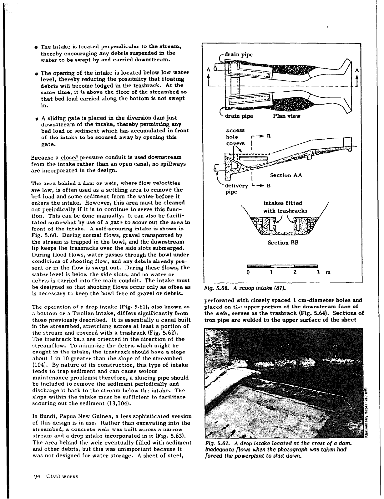
e The intake is located perpendicular to the stream,
thereby encouraging any debris suspended in the
water to be swept by and carried downstream.
e The opening of the intake is located below low water
level, thereby reducing the possibility that floating
debris will become lodged in the trashrack. At the
same time, it is above the floor of the streambed so
that bed load carried along the bottom is not swept
ln.
e A sliding gate is placed in the diversion dam just
downstream of the intake, thereby permitting any
bed load or sediment which has accumulated in front
of
the intake to be scoured away by opening this
gate.
Because a closed pressure conduit is used downstream
--
from the intake rather than an open canal, no spillways
are incorporated in the design.
The area behind a dam or weir, where flow velocities
are low, is often used as a settling area to remove the
bed load and some sediment from the water before it
enters the intake. However, this area must be cleaned
out periodically if it is to continue to serve this func-
tion. This can be done manually. It can also be facili-
tated somewhat by use of a gate to
scour
out the
area
in
front of the intake. A self-scouring intake is shown in
Fig. 5.60. During normal flows, gravel transported by
the stream is trapped in the bowl, and the downstream
lip keeps the trashracks
over
the side slots submerged.
During flood flows, water passes through the bowl under
conditions of shooting flow, and any debris already pre-
sent
or
in the flow is swept out. During these flows, the
water level is below the side slots, and no water or
debris is carried into the main conduit. The intake must
be designed
so
that shooting flows occur only as often as
is necessary to keep the bowl free of gravel or debris.
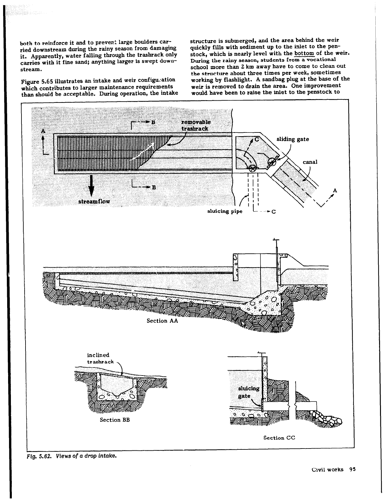
The operation of a drop intake (Fig. 5.61), also known as
a bottom or a Tirolian intake, differs significantly from
those previously described. It is essentially a canal built
in the streambed, stretching across at least a portion of
the stream and covered with a trashrack (Fig. 5.62).
The trashrack ba.s arc oriented in the direction of the
streamflow. To minimize the debris which might be
caught in the intake, the trashrack should have a slope
about 1 in 10 greater than Lhe slope of the streambed
(104). By nature of its construction, this type of intake
tends to trap sediment and can cause serious
maintenance problems; therefore, a sluicing pipe should
be included to remove the sediment periodically and
discharge it back to the stream below the intake. The
slope within the intake must be sufficient to facilitate
scouring out
the
sediment (13,104).
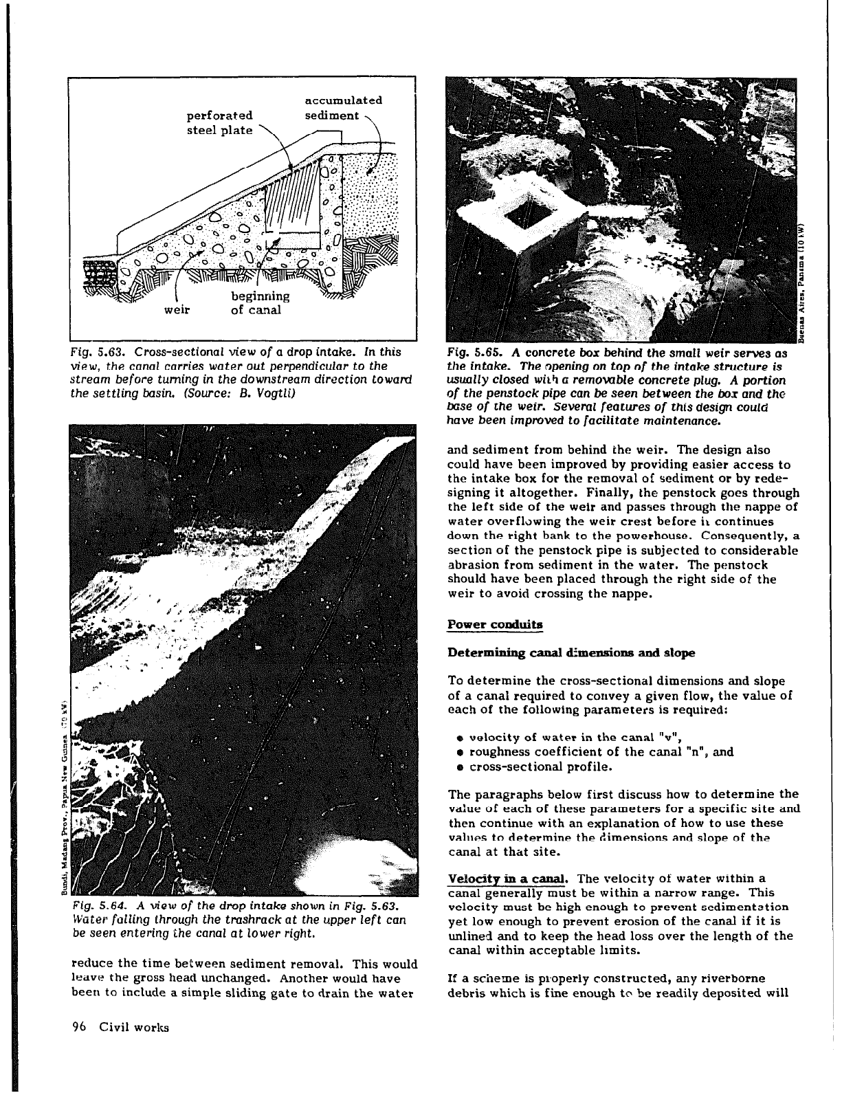
In Bundi, Papua New Guinea, a less sophisticated version
of this design is in use. Rather than excavating into the
streambed, a concrete weir was built across a narrow
stream and a drop intake incorporated in it (Fig. 5.63).
The area behind the weir eventually filled with sediment
and other debris, but this was unimportant because it
was not designed for water storage. A sheet of steel,
w
04
civil works
F drain piw
A
t
L drairx pipe Plan view
access
Section AA
delivery L + B
pipe
intakes fitted
\
with trashracks
/
Section BB
t
I
I
4
0
1 2
3 m
Fig. 5.60.
A scc-op intake (871.
perforated with closely spaced 1 cm-diameter holes and
placed on tLz upper portion of the downstream face of
the weir,
serves
as the trashsack (Fig. 5.64). Sections of
iron pipe are welded to the upper surface of the sheet
Fig. 5.61. A drop intake located
at
the crest
of
a dam.
Inadequate fZows when the photograph was taken had
forced the powerplant to shut
down.
both to reinforce it and to preven: large boulders car-
ried downstream during the rainy season from damaging
it. Apparently, water falling through the trashrack only
carries with it fine sand; anything larger is swept down-
stream.
Figure 5.65 illustrates an intake and weir configuration
which contributes to larger maintenance requirements
than should be acceptable. During operation, the intake
structure is submerged, and the area behind the weir
quickly fills with sediment up to the inlet to the pen-
stock, which is nearly level with the bottom of the weir.
During the rainy season, students from a vocational
school
more
than 2 km away have to come to clean out
the structure about three times per week, sometimes
working by flashlight. A sandbag plug at the base of the
weir is removed to drain the area. One improvement
would have been to raise the inlet to the penstock to
sluicing pipe
L - -C
inclined
Section BB
Section CC
Fig. 5.62.
Views
of
a
dmp
intake.
Civil works 95
accumulated
weir
Fig. 5.63. Cross-sectional view of a drop intake. In this
view,
the
canal carries
water out
perpendicular to
the
stream before turning in the downstream direction toward
the
settling
basin.
(Source: 8. Vogtli)
Fig. 5.64. A view of
the
drop intake shown in
Fig. 5.63.
Water failing through the tmshrack at
the
upper left can
be
seen
entering ihe canal at
lower right.
reduce the time between sediment removal. This would
leave the gross head unchanged. Another would have
been to include a simple sliding gate to drain the water
96 Civil works
Fig. 5.65. A concrete box &hind the small weir serves (IS
the
intake.
The
opening on
top
of
the
intake
structure is
usually closed with a removable concrete plug. A
portion
of
the
penstock pipe can
be seen between
the
box and the
&se of the weir. Several
features
of this design could
have been
improved to facilitate
maintenance.
and sediment from behind the weir. The design also
could have been improved by providing easier access to
the intake box for the removal of sediment or by rede-
signing it altogether. Finally, the penstock goes through
the left side of the weir and passes through the nappe of
water overfltiwing the weir crest before ii continues
down the right bank to the powerhouse. Consequently, a
section of the penstock pipe is subjected to considerable
abrasion from sediment in the water. The penstock
should have been placed through the right side of the
weir to avoid crossing the nappe.
Power conduits
Determining canal dimeusions and slope
To determine the cross-sectional dimensions and slope
of a canal required to convey a given flow, the value of
each of the following parameters is requited:
e velocity of water in the canal “9,
o roughness coefficient of the canal “n”, and
e cross-sectional profile.
The paragraphs below first discuss how to determine the
value of each of these parameters for a specific site and
then continue with an explanation of how to use these
values to determine the dimensions and slope of the
canal at that site.
Velocity in a canal. The velocity of water within a
canal generally must be within a narrow range. This
velocity must be high enough to prevent sedimentation
yet low enough to prevent erosion of the canal if it is
unlined and to keep the head loss over the length of the
canal within acceptable limits.
If a scheme is properly constructed, any riverborne
debris which is fine enough to be readily deposited will
have settled either in the reservoir or pond before the
intake or in a settling basin just before the beginning of
the canal. The velocity in the canal should be high
enough so that any susp,nded material which has not
settled out in the settling area will not do so in the
canal. To keep any silt still in suspension from settling
Gut, t!ie average minimum flow velocity in a canal
should be (39):
‘min
= 0.3 m/s for silty water
= 0.3-0.5 m/s for water carrying fine sand
0 .05
0.04
R
.
%
.C(
v
2
8
;
0.03
3
Y
2
0.02
-
Earth
l
partially obstructed with
debris and weeds
- a rock cuts, jagged and -
irregular
l
stony bed and weeds on bank
-m rock cuts, smooth and -
uniform
l
dry-rubble surface
l
ordinary conditions
-• regular surface, good
condition, or well-packed
gravel
l
uniform, very good
conditions
Apart from this consideration, the growth of aquatic
plants in earth canals can seriously affect their capacity
in some climates. This is rarely serious if water tem-
perature is below 20 oC or the water is turbid
or
deep.
A mean velocity of greater than 0.7 m/s will generally
prevent growth that can seriously affect the flow in a
canal (38).
To minimize the cost and labor necessary to construct a
canal, the velocity in the canal must be maximized.
The greater the velocity, the smaller the required
cross-
Nature of canal surface and finish
Masonry and Brickwork
l
masonry in bad condition
or inferior brick or stone
Metal
B corrugated
semicircular
l
slightly -
tuberculated
l
rough-face brickwork
0 riveted
l
concrete, wood troweled
l
sand and cement plaster
a cast or
wrought iron
l
unplaned, badly
fitted or aged
1
l
well laid, unplaned 4
0 neat cement plaster
l
glazed
l
well planed and
fitted
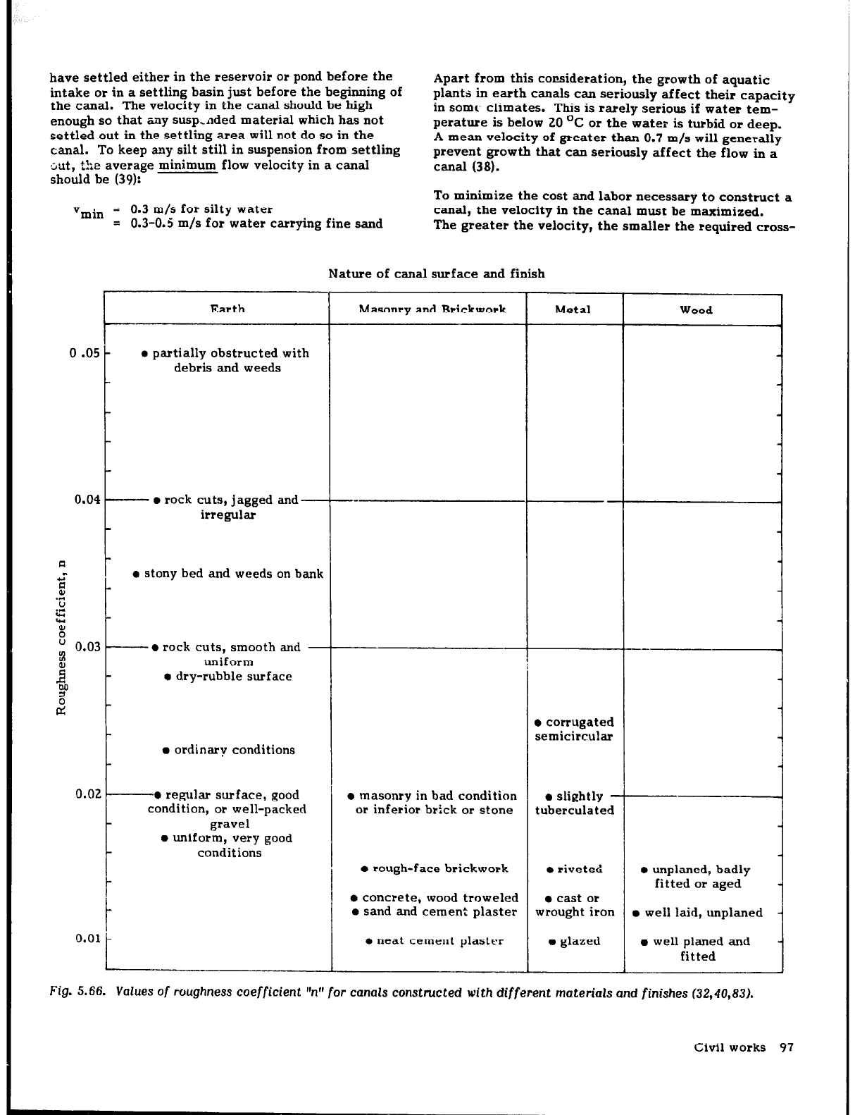
Fig. 5.66.
Values of roughness coefficient
‘W
for canals constructed with different
materials and
finishes (32,40,83).
Civil works 97
sectional area of the canal and the smaller the volume
to be excavated. Canals for micro-hydropower schemes
are often unlined because of the cost savings this
implies. However, there is a maximum permissible
velocity above which the hanks and bottom of an unlined
canal will start eroding. The magnitude of this velocity
depends on the nature of the soil. For bare
c2nals,
approximate values of this maximum velocity are shown
in Table 5.1. APPRNDM C (p. 269) explains how to
ascertain the nature ol the soil at a specific site.
TABLE 5.1. Maxfmum pe*mbfWe vekxftfes to
awofd em
sion in an earth canal (38,40,83)
Typeofsofl
Fine sand
Sandy loam
Clayey loam
Clay
velocity
b/d
0.3-0.4
0.4-0.6
0.6-0.8
0.8-2.0
If the canal is lined, wear by abrasion sets the upper
limit on velocity. For clear water in concrete canals,
velocities above 10 m/s have been found to do no harm.
However, if the water contains sand, gravel,
or
stones,
damage may occur at much lower velocities. Unless the
abrasive material is particularly bad, velocities up to
4 m/s should not injure wood or quality concrete. Thin
metal flumes may be damaged by coarse sand or gravel
at 2-3 m/s, and the galvanizing that might cover the
sheet metal may be injured at even lower velocities
(401.
Roughne~ coefficient. The roughness coefficient ‘n”,
also called Manning’s coefficient, is an empirical neas-
ure of the roughness of a surface. Its value for canals
ranges from 0.010 for those with the smoothest finish to
about 0.050 and more for earth canals in very poor con-
dition and obstructed with weeds and debris. The value
of ‘In” for an average canal ranges from 0.012 to 0.023.
Value- of “n“ for various materials and finishes are
shown in Fig. 5.66. Although a specific value of “n” has
been assigned for each canal surface described, the
actual value of ‘ii” may vary by kO.005
or
even more.
For this reason, the figure has been prepared to give the
reader a feel for the sensitivity of “n” to the actual sur-
face roughness.
Cross-sectional profile. The material in which the canal
is excavaled or of which it is constructed generally dic-
tates its cross-sectional profile. The following para-
graphs describe the common profiles used for canals and
when each is used.
A semicircular cross-section is the
most efficient profile because, for
I-d-1
a given canal slope and cross-sec-
I
I
tional area, it passes the maximum
flow or discharge. However, this
form is impractical to excavate. It
is therefore used primarily with materials which lend
themselves to this shape. Examples are prefabricated
concrete, sheet-metal, and wood-stave sections. Illus-
trations of these can be found in Plumes (p. 112).
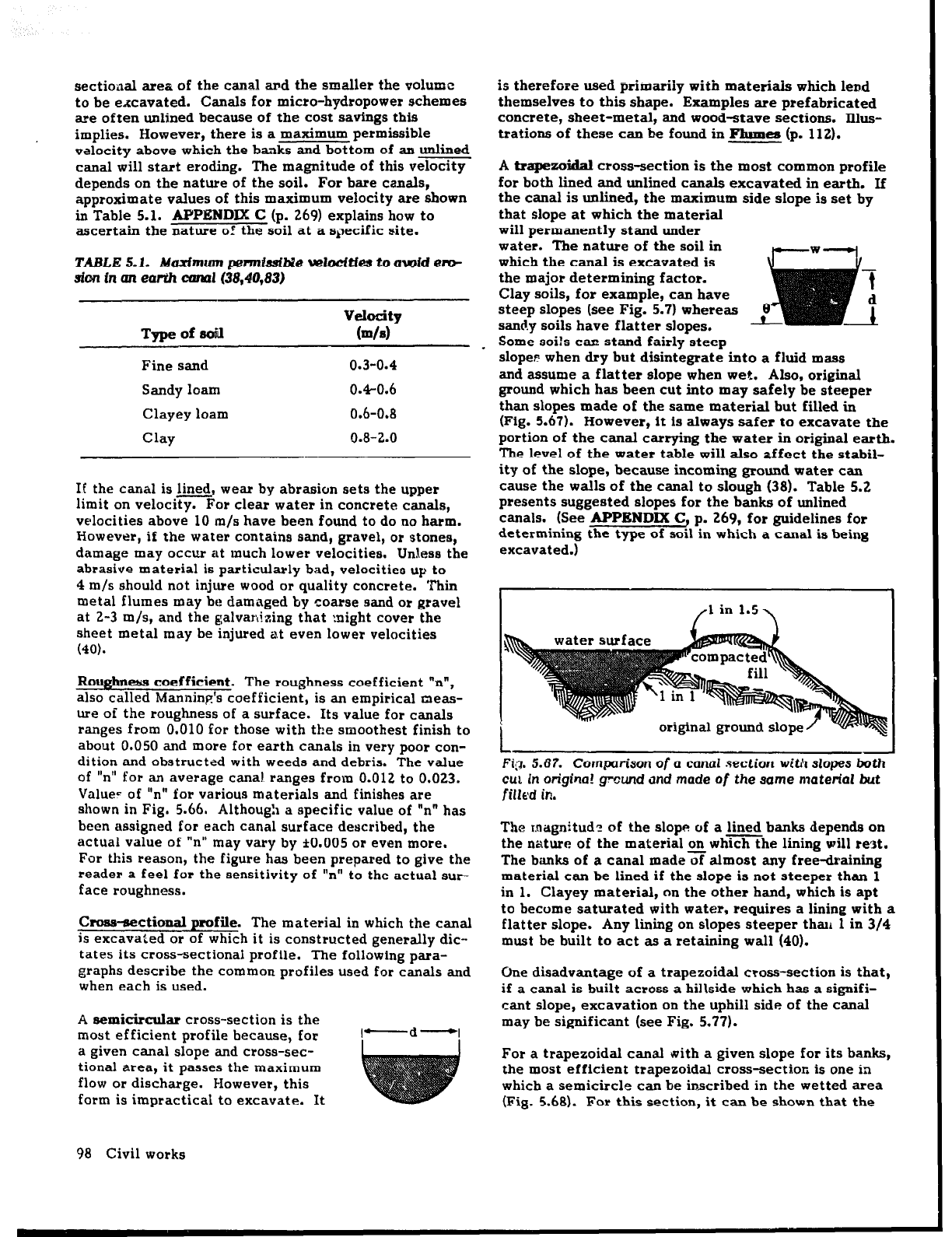
A trapexoldal cross-section is the most common profile
for both lined and unlined canals excavated in earth. If
the canal is unlined, the maximum side slope is set by
that slope at which the material
will permanently stand under
water. The nature of the soil in
which the canal is excavated is
the major determining factor.
Clay soils, for example, can have
steep slopes (see Fig. 5.71 whereas
sandy soils have flatter slopes.
Some soils can stand fairly steep
slope? when dry but disintegrate into a fluid mass
and assume a flatter slope when wet. Also, original
ground which has been cut into may safely be steeper
than slopes made of the same material but filled in
(Fig. 5.67). However, it is always safer to excavate the
portion of the canal carrying the water in original earth.
The level of the water table will also affect the stabil-
ity of the slope, because incoming ground water can
cause the walls
of
the canal to slough (38). Table 5.2
presents suggested slopes for the banks of unlined
canals. (See APPEND= C, p. 269, for guidelines for
determining the type of soil in which a canal is being
excavated.1
/l in 1.5~
FQ. 5.67. Com~xrrison
of
a
cam1
section witl’l slopes both
GUI
In
origina! ground
and made of the same
material but
filled
in.
The raagnitudz of the slope of a lined banks depends on
the nature
of
the material on whmhe lining will rest.
The banks of a canal madexalmost any free-draining
material can be lined if the slope is not steeper than 1
in 1. Clayey material, on the other hand, which is apt
to become saturated with water, requires a lining with a
flatter slope. Any lining on slopes steeper than 1 in 3/4
must be built to act as a retaining wall (40).
Une disadvantage of a trapezoidal cross-section is that,
if a canal is built across a hillside which has a signifi-
cant slope, excavation on the uphill side of the canal
may be significant (see Fig. 5.77).
For a trapezoidal canal with a given slope
for
its banks,
the most efficient trapezoidal cross-section is one in
which a semicircle can be inscribed in the wetted area
(Fig. 5.68). For this section, it can be shown that the
98 Civil works
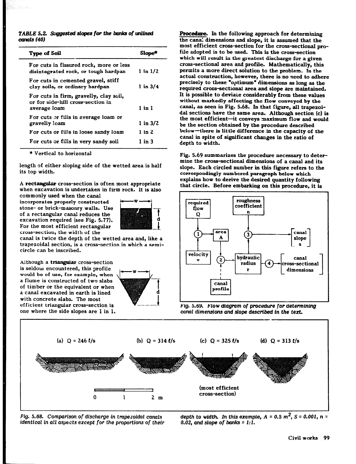
TABLE5.2. tJugg&ddopeJfwthebankrof~
avmls (40)
TypeOfSOil
Slope’
For cuts in fissured rock,
more or
less
disintegrated rock, or tough hardpan
1
in
l/2
For cuts in cemented gravel, stiff
clay soils, or ordinary hardpan
I in 314
For cuts in firm, gravelly, clay soil,
or for side-hill cross-section in
average loam
1 in 1
For cuts ,or fills in average loam or
gravelly loam 1 in 312
For cuts
or
fills in loose sandy loam
1 in 2
For cuts or fills in very sandy soil 1 in 3
* Vertical
to
horizontal
length of either sloping side of the wetted area is half
its top width.
A rectangular cross-section is often most appropriate
when excavation is undertaken in firm rock. It is also
commonly used when the canal
incorporates properly constructed ew -I
stone- or brick-masonry walls. Use
of a rectangular canal reduces the 7
excavation required (see Fig. 5.77).
For the most efficient rectangular
4
cross-section, the width of the
canal is twice the depth of the wetted area and, like a
trapezoidal section, is a cross-section in which a semi-
circle can be inscribed.
Although a triangular cross-section
is seldom encountered, this profile
would be of use, for example, when
a flume is constructed of two slabs
of timber or the equivalent or when
a canal excavated in earth is lined
with concrete slabs. The most
efficient triaugular cross-section is
one where the side slopes are 1 in 1.
Rocedme. In the following approach for determining
the canal dimensions and slope, it is
assumed that the
most efficient cross-section for the cross-sectional pro-
file adopted is to be used. This is the cross-section
which will result in the greatest discharge for a given
cross-sectional area and profile. Mathematically, this
permits a more direct solution to the problem. In the
actual construction, however, there is no need to adhere
precisely to these .optimumn dimensions as long as the
required cross-sectional area and slope are maintained.
It is possible to deviate considerably from these vaIues
without markedly affecting the flow conveyed by the
canal, as seen in Fig. 5.68. In that figure, all trapezoi-
dal sections have the same area. Although section (c) is
the most efficient-it conveys maximum flow and would
be the section obtained by the procedure described
below-there is little difference in the capacity of the
canal in spite of significant cbges in the ratio of
depth to width.
Fig. 5.69 summarizes the procedure necessary to deter-
mine the cross-sectional dimensions
of
a canal and its
slope. Each circled number in this figure refers to the
correspondingly numbered paragraph below which
explains how to derive the desired quantity following
that circle. Before embarking on this procedure, it is
required
flow
Q
%
roughness
coefficient
v
1
Y &pfq
rig. 5.69. Flow diagram
of
procedure for determining
canal dimensions and slope described
In the
text.
1
2m
(most efficient
cross-section)
(a) Q = 246 C/s (b) Q = 314 t/s
(c) Q = 325 t/s
(d) Q = 313 C/s
Fig. 5.68. Comparison
of discharge in trapezoidal con&s
identical In
all aspects except for
the proportions
of their
depth to width. In this example, A = 0.5 m’, S = 0.001,
n -
0.02, and slope of bank3 = 1~1.
Civil works 99