Neamen D. Microelectronics: Circuit Analysis and Design
Подождите немного. Документ загружается.

38 Part 1 Semiconductor Devices and Basic Applications
For
V
D
≥ V
γ
, we assume a straight-line approximation whose slope is
1/r
f
,
where
V
γ
is the turn-on, or cut-in, voltage of the diode, and
r
f
is the forward diode
resistance. The equivalent circuit for this linear approximation is a constant-voltage
source in series with a resistor (Figure 1.31(a)).
2
For
V
D
< V
γ
, we assume a straight-line
I
D
= – I
S
I
S
I
D
V
D
V
g
Slope =
1
r
f
Figure 1.30 The diode I–V characteristics and two linear approximations. The linear
approximations form the piecewise linear model of the diode.
2
It is important to keep in mind that the voltage source in Figure 1.31(a) only represents a voltage drop for
V
D
≥ V
γ
. When
V
D
< V
γ
, the
V
γ
source does not produce a negative diode current. For
V
D
< V
γ
, the
equivalent circuit in Figure 1.31(b) must be used.
I
D
(mA)
V
D
(volts)
3.0
≈ 2.2
≈0.62
2.0
1.5
1.0
0.5
0
1 2 3 4 5
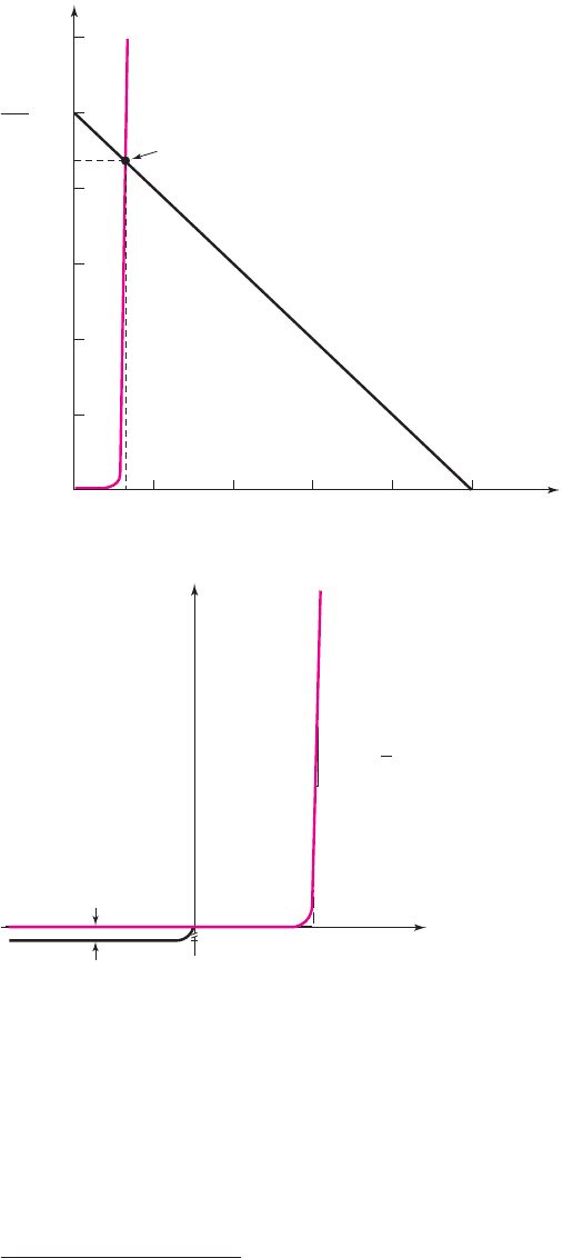
Diode I–V
characteristics
Q-point
Load line
= 2.5
V
PS
R
Figure 1.29 The diode and load line characteristics for the circuit shown in Figure 1.28
nea80644_ch01_07-066.qxd 06/08/2009 05:15 PM Page 38 F506 Tempwork:Dont' Del Rakesh:June:Rakesh 06-08-09:MHDQ134-01 Folder:MHDQ134-01:

Chapter 1 Semiconductor Materials and Diodes 39
approximation parallel with the
V
D
axis at the zero current level. In this case, the
equivalent circuit is an open circuit (Figure 1.31(b)).
This method models the diode with segments of straight lines; thus the name
piecewise linear model. If we assume
r
f
= 0
, the piecewise linear diode character-
istics are shown in Figure 1.31(c).
EXAMPLE 1.9
Objective: Determine the diode voltage and current in the circuit shown in Fig-
ure 1.28, using a piecewise linear model. Also determine the power dissipated in the
diode.
Assume piecewise linear diode parameters of
V
γ
= 0.6
V and
r
f
= 10
.
Solution: With the given input voltage polarity, the diode is forward biased or
“turned on,” so
I
D
> 0
. The equivalent circuit is shown in Figure 1.31(a). The diode
current is determined by
I
D
=
V
PS
− V
γ
R +r
f
=
5 − 0.6
2 × 10
3
+10
⇒ 2.19 mA
and the diode voltage is
V
D
= V
γ
+ I
D
r
f
= 0.6 +(2.19 ×10
−3
)(10) = 0.622 V
The power dissipated in the diode is given by
P
D
= I
D
V
D
We then find
P
D
= (2.19)(0.622) = 1.36 mW
Comment: This solution, obtained using the piecewise linear model, is nearly equal
to the solution obtained in Example 1.8, in which the ideal diode equation was used.
However, the analysis using the piecewise-linear model in this example is by far eas-
ier than using the actual diode I–V characteristics as was done in Example 1.8. In
general, we are willing to accept some slight analysis inaccuracy for ease of analysis.
+
–
+
–
V
D
V
g
I
D
r
f
+
–
V
D
I
D
I
D
V
D
V
g
(
a
)
(b)
(
c
)
Figure 1.31 The diode piecewise equivalent circuit (a) in the “on” condition when
V
D
≥ V
γ
,
(b) in the “off’ condition when
V
D
< V
γ
, and (c) piecewise linear approximation when
r
f
= 0
. When
r
f
= 0
, the voltage across the diode is a constant at
V
D
= V
γ
when the diode
is conducting.
nea80644_ch01_07-066.qxd 06/08/2009 05:15 PM Page 39 F506 Tempwork:Dont' Del Rakesh:June:Rakesh 06-08-09:MHDQ134-01 Folder:MHDQ134-01:

40 Part 1 Semiconductor Devices and Basic Applications
EXERCISE PROBLEM
Ex 1.9: (a) Consider the circuit shown in Figure 1.28. Let
V
PS
= 8V
and
V
γ
= 0.7V,
Assume
r
f
= 0
. Calculate the value of R such that
I
D
= 1.20 mA.
(b) If
V
PS
is reduced to 4 V and R is changed to
3.5k
, determine the power dis-
sipated in the diode. (Ans. (a)
6.08 k
, (b) 0.66 mW).
Because the forward diode resistance
r
f
in Example 1.9 is much smaller than the
circuit resistance R, the diode current
I
D
is essentially independent of the value of
r
f
.
In addition, if the cut-in voltage is 0.7 V instead of 0.6 V, the calculated diode current
will be 2.15 mA, which is not significantly different from the previous results. There-
fore, the calculated diode current is not a strong function of the cut-in voltage.
Consequently, we will often assume a cut-in voltage of 0.7 V for silicon pn junction
diodes.
The concept of the load line and the piecewise linear model can be combined in
diode circuit analyses. From Kirchhoff’s voltage law, the load line for the circuit
shown in Figure 1.28 and for the piecewise linear model of the diode can be written
as
V
PS
= I
D
R + V
γ
where
V
γ
is the diode cut-in voltage. We can assume
V
γ
= 0.7V
. Various load lines
can be determined and plotted for the following circuit conditions:
A:
V
PS
= 5
V,
R = 2k
B:
V
PS
= 5
V,
R = 4k
C:
V
PS
= 2.5
V,
R = 2k
D:
V
PS
= 2.5
V,
R = 4k
The load line for condition A is plotted in Figure 1.32(a). Also plotted in the figure
are the piecewise linear characteristics of the diode. The intersection of the two
curves corresponds to the Q-point. For this case, the quiescent diode current is
I
DQ
∼
=
2.15 mA
.
Figure 1.32(b) shows the same piecewise linear characteristics of the diode. In
addition, all four load lines, defined by the conditions listed above in A, B, C, and D
are plotted on the figure. We see that the Q-point of the diode is a function of the load
line. The Q-point changes for each load line.
The load line concept is also useful when the diode is reverse biased. Figure 1.33 (a)
shows the same diode circuit as before, but with the direction of the diode reversed.
2.5
5 0.7 V
Q-point
I
D
(mA) I
D
(mA)
V
D
(volts) V
D
(volts)
2.15
2.5
0.7 2.5 5
V
PS
= 5 V
V
PS
= 2.5 V
R = 4 kΩ
R = 2 kΩ
1.25
0.625
(a) (b)
Q-points
Figure 1.32 Piecewise linear diode approximation superimposed on (a) load line for
V
PS
= 5V, R = 2k
and (b) several load lines. The Q-point of the diode changes when the
load line changes.
nea80644_ch01_07-066.qxd 06/08/2009 05:15 PM Page 40 F506 Tempwork:Dont' Del Rakesh:June:Rakesh 06-08-09:MHDQ134-01 Folder:MHDQ134-01:

Chapter 1 Semiconductor Materials and Diodes 41
The diode current
I
D
and voltage
V
D
shown are the usual forward-biased parameters.
Applying Kirchhoff’s voltage law, we can write
V
PS
= I
PS
R − V
D
=−I
D
R − V
D
(1.25(a))
or
I
D
=−
V
PS
R
−
V
D
R
(1.25(b))
where
I
D
=−I
PS
. Equation (1.25(b)) is the load line equation. The two end points
are found by setting
I
D
= 0
, which yields
V
D
=−V
PS
=−5V
, and by setting
V
D
= 0
, which yields
I
D
=−V
PS
/R =−5/2 =−2.5mA
. The diode characteris-
tics and the load line are plotted in Figure 1.33(b). We see that the load line is now in
the third quadrant, where it intersects the diode characteristics curve at
V
D
=−5V
and
I
D
= 0
, demonstrating that the diode is reverse biased.
Although the piecewise linear model may yield solutions that are less accurate
than those obtained with the ideal diode equation, the analysis is much easier.
Computer Simulation and Analysis
Today’s computers are capable of using detailed simulation models of various com-
ponents and performing complex circuit analyses quickly and relatively easily. Such
models can factor in many diverse conditions, such as the temperature dependence of
various parameters. One of the earliest, and now the most widely used, circuit analy-
sis programs is the simulation program with integrated circuit emphasis (SPICE).
This program, developed at the University of California at Berkeley, was first re-
leased about 1973, and has been continuously refined since that time. One outgrowth
of SPICE is PSpice, which is designed for use on personal computers.
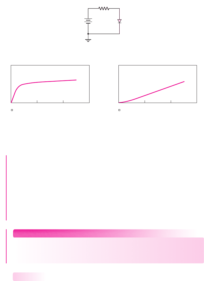
EXAMPLE 1.10
Objective: Determine the diode current and voltage characteristics of the circuit
shown in Figure 1.28 using a PSpice analysis.
Solution: Figure 1.34(a) is the PSpice circuit schematic diagram. A standard
1N4002 diode from the PSpice library was used in the analysis. The input voltage V1
was varied (dc sweep) from 0 to 5 V. Figure 1.34(b) and (c) shows the diode voltage
and diode current characteristics versus the input voltage.
1.3.3
+
–
+
–
V
PS
= 5 V
I
PS
I
D
V
D
R = 2 kΩ
I
D
V
D
V
g
–5
Load line
–2.5 mA
Q-point
(a) (b)
Figure 1.33 Reverse-biased diode (a) circuit and (b) piecewise linear approximation and
load line
nea80644_ch01_07-066.qxd 06/08/2009 05:15 PM Page 41 F506 Tempwork:Dont' Del Rakesh:June:Rakesh 06-08-09:MHDQ134-01 Folder:MHDQ134-01:
42 Part 1 Semiconductor Devices and Basic Applications
Discussion: Several observations may be made from the results. The diode voltage
increases at almost a linear rate up to approximately 400 mV without any discernible
(mA) current being measured. For an input voltage greater than approximately
500 mV, the diode voltage increases gradually to a value of about 610 mV at the max-
imum input voltage. The current also increases to a maximum value of approximately
2.2 mA at the maximum input voltage. The piecewise linear model predicts quite
accurate results at the maximum input voltage. However, these results show that there is
definitely a non-linear relation between the diode current and diode voltage. We must
keep in mind that the piecewise linear model is an approximation technique that
works very well in many applications.
EXERCISE PROBLEM
Ex 1.10: The resistor parameter in the circuit shown in Figure 1.28 is changed to
R = 20 k
. Using a PSpice analysis, plot the diode current
I
D
and diode voltage
V
D
versus the power supply voltage
V
PS
over the range
0 ≤ V
PS
≤ 10 V
.
Summary of Diode Models
The two dc diode models used in the hand analysis of diode circuits are: the ideal
diode equation and the piecewise linear approximation. For the ideal diode equation,
the reverse-saturation current
I
S
must be specified. For the piecewise linear model,
the cut-in voltage
V
γ
and forward diode resistance
r
f
must be specified. In most
cases, however,
r
f
is assumed to be zero unless otherwise given.
The particular model that should be used in a specific application or situation is
a compromise between accuracy and ease of calculation. This decision comes with
experience. In general, a simple model can be used in an initial design for ease of
1.3.4
1N4002
D
1
R
1
V
1
2 k
0
+
–
(a)
(b)
(A) Diode 2A.dat (A) Diode 2A.dat
1.0 V
0 V
0 V 2.0 V 4.0 V 6.0 V
V(D1:1)
V V1
(c)
4.0 mA
0 A
0 V 2.0 V 4.0 V 6.0 V
I(D1)
V V1
Figure 1.34 (a) PSpice circuit schematic, (b) diode voltage, and (c) diode current for
Example 1.10
nea80644_ch01_07-066.qxd 06/08/2009 05:15 PM Page 42 F506 Tempwork:Dont' Del Rakesh:June:Rakesh 06-08-09:MHDQ134-01 Folder:MHDQ134-01:

Chapter 1 Semiconductor Materials and Diodes 43
calculation. In a final design, we may want to use a computer simulation for better
accuracy. However, it is very important to understand that the diode model or diode
parameters used in the computer simulation must correspond to the actual diode
parameters used in the circuit to ensure that the results are meaningful.
Test Your Understanding
TYU 1.9 Consider the diode and circuit in Exercise EX 1.8. Determine
V
D
and
I
D
,
using the graphical technique. (Ans.
V
D
∼
=
0.54
V,
I
D
∼
=
0.87
mA)
TYU 1.10 Consider the circuit in Figure 1.28. Let
R = 4k
and
V
γ
= 0.7
V. Deter-
mine
I
D
for (a)
V
PS
= 0.5V
, (b)
V
PS
= 2V
, (c)
V
PS
= 5V
, (d)
V
PS
=−1V
, and
(e)
V
PS
=−5V
. (Ans. (a) 0, (b) 0.325 mA, (c) 1.075 mA, (d) 0, (e) 0).
TYU 1.11 The power supply (input) voltage in the circuit of Figure 1.28 is
V
PS
=
10 V and the diode cut-in voltage is
V
γ
= 0.7
V (assume
r
f
= 0
). The power dissi-
pated in the diode is to be no more than 1.05 mW. Determine the maximum diode
current and the minimum value of R to meet the power specification. (Ans.
I
D
= 1.5
mA,
R = 6.2
k
)
1.4 DIODE CIRCUITS: AC EQUIVALENT CIRCUIT
Objective: • Develop an equivalent circuit for a diode that is used
when a small, time-varying signal is applied to a diode circuit.
Up to this point, we have only looked at the dc characteristics of the pn junction
diode. When semiconductor devices with pn junctions are used in linear amplifier
circuits, the time-varying, or ac, characteristics of the pn junction become important,
because sinusoidal signals may be superimposed on the dc currents and voltages. The
following sections examine these ac characteristics.
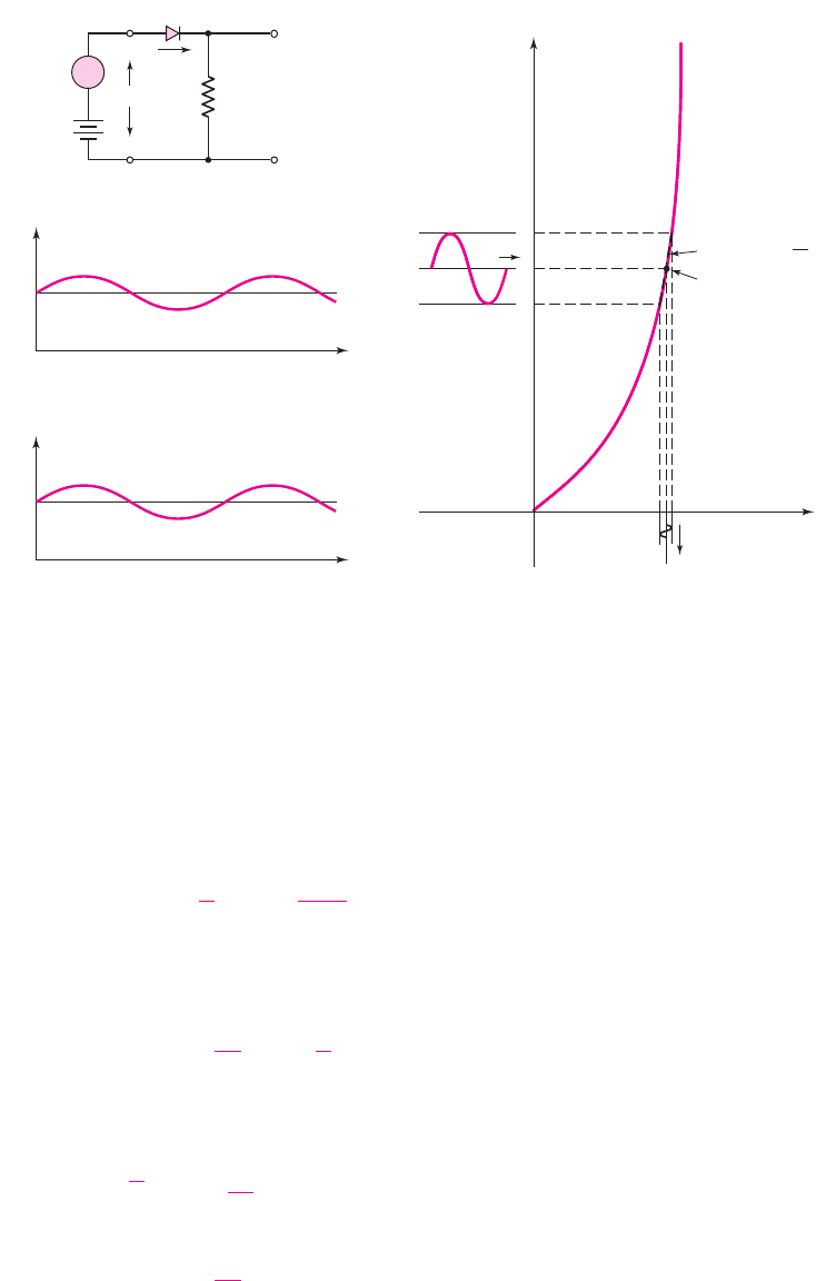
Sinusoidal Analysis
In the circuit shown in Figure 1.35(a), the voltage source
v
i
is assumed to be a sinu-
soidal, or time-varying, signal. The total input voltage
v
I
is composed of a dc
component
V
PS
and an ac component
v
i
superimposed on the dc value. To investigate
this circuit, we will look at two types of analyses: a dc analysis involving only the dc
voltages and currents, and an ac analysis involving only the ac voltages and currents.
Current–Voltage Relationships
Since the input voltage contains a dc component with an ac signal superimposed,
the diode current will also contain a dc component with an ac signal superimposed, as
shown in Figure 1.35(b). Here,
I
DQ
is the dc quiescent diode current. In addition, the
diode voltage will contain a dc value with an ac signal superimposed, as shown in
Figure 1.35(c). For this analysis, assume that the ac signal is small compared to the dc
component, so that a linear ac model can be developed from the nonlinear diode.
1.4.1
nea80644_ch01_07-066.qxd 06/08/2009 05:15 PM Page 43 F506 Tempwork:Dont' Del Rakesh:June:Rakesh 06-08-09:MHDQ134-01 Folder:MHDQ134-01:
44 Part 1 Semiconductor Devices and Basic Applications
The relationship between the diode current and voltage can be written as
i
D
∼
=
I
S
e
v
D
V
T
= I
S
e
V
DQ
+v
d
V
T
(1.26)
where
V
DQ
is the dc quiescent voltage and
v
d
is the ac component. We are neglecting
the
−1
term in the diode equation given by Equation (1.22). Equation (1.26) can be
rewritten as
i
D
= I
S
e
V
DQ
V
T
·
e
v
d
V
T
(1.27)
If the ac signal is “small,” then
v
d
V
T
, and we can expand the exponential func-
tion into a linear series, as follows:
e
v
d
V
T
∼
=
1 +
v
d
V
T
(1.28)
We may also write the quiescent diode current as
I
DQ
= I
S
e
V
DQ
V
T
(1.29)
(b)
(a)
+
+
–
–
+
–
v
O
V
PS
+
–
R
+
–
v
I
v
i
v
D
i
D
I
D
i
d
I
DQ
Time
(c)
v
D
V
DQ
Time
v
d
i
D
v
D
t
V
DQ
I
DQ
t
Q-point
Slope = g
d
=
1
r
d
(d)
Figure 1.35 AC circuit analysis: (a) circuit with combined dc and sinusoidal input
voltages, (b) sinusoidal diode current superimposed on the quiescent current, (c) sinusoidal
diode voltage superimposed on the quiescent value, and (d) forward-biased diode
I–V
characteristics with a sinusoidal current and voltage superimposed on the quiescent
values
nea80644_ch01_07-066.qxd 06/08/2009 05:15 PM Page 44 F506 Tempwork:Dont' Del Rakesh:June:Rakesh 06-08-09:MHDQ134-01 Folder:MHDQ134-01:

Chapter 1 Semiconductor Materials and Diodes 45
The diode current–voltage relationship from Equation (1.27) can then be written as
i
D
= I
DQ
1 +
v
d
V
T
= I
DQ
+
I
DQ
V
T
· v
d
= I
DQ
+i
d
(1.30)
where
i
d
is the ac component of the diode current. The relationship between the ac
components of the diode voltage and current is then
i
d
=
I
DQ
V
T
· v
d
= g
d
· v
d
(1.31(a))
or
v
d
=
V
T
I
DQ
·i
d
= r
d
·i
d
(1.31(b))
The parameters
g
d
and
r
d
, respectively, are the diode small-signal incremental con-
ductance and resistance, also called the diffusion conductance and diffusion
resistance. We see from these two equations that
r
d
=
1
g
d
=
V
T
I
DQ
(1.32)
This equation tells us that the incremental resistance is a function of the dc bias cur-
rent
I
DQ
and is inversely proportional to the slope of the I–V characteristics curve, as
shown in Figure 1.35(d).
Circuit Analysis
To analyze the circuit shown in Figure 1.35(a), we first perform a dc analysis and
then an ac analysis. These two types of analyses will use two equivalent circuits.
Figure 1.36(a) is the dc equivalent circuit that we have seen previously. If the diode
is forward biased, then the voltage across the diode is the piecewise linear turn-on
voltage.
Figure 1.36(b) is the ac equivalent circuit. The diode has been replaced by its
equivalent resistance
r
d
. All parameters in this circuit are the small-signal time-
varying parameters.
EXAMPLE 1.11
Objective: Analyze the circuit shown in Figure 1.35(a).
Assume circuit and diode parameters of
V
PS
= 5
V,
R = 5
k
,
V
γ
= 0.6
V, and
v
i
= 0.1 sin ωt(V).
+
–
v
o
r
d
v
i
R
+
–
i
d
+
+
–
–
+
–
V
O
V
DQ
= V
g
V
PS
I
DQ
(a) (b)
R
Figure 1.36 Equivalent circuits: (a) dc and (b) ac
nea80644_ch01_07-066.qxd 06/08/2009 05:15 PM Page 45 F506 Tempwork:Dont' Del Rakesh:June:Rakesh 06-08-09:MHDQ134-01 Folder:MHDQ134-01:

46 Part 1 Semiconductor Devices and Basic Applications
Solution: Divide the analysis into two parts: the dc analysis and the ac analysis.
For the dc analysis, we set
v
i
= 0
and then determine the dc quiescent current
from Figure 1.36(a) as
I
DQ
=
V
PS
− V
γ
R
=
5 − 0.6
5
= 0.88 mA
The dc value of the output voltage is
V
o
= I
DQ
R = (0.88)(5) = 4.4V
For the ac analysis, we consider only the ac signals and parameters in the circuit
in Figure 1.36(b). In other words, we effectively set
V
PS
= 0
. The ac Kirchhoff volt-
age law (KVL) equation becomes
v
i
= i
d
r
d
+i
d
R = i
d
(r
d
+ R)
where
r
d
is again the small-signal diode diffusion resistance. From Equation (1.32),
we have
r
d
=
V
T
I
DQ
=
0.026
0.88
= 0.0295 k
The ac diode current is
i
d
=
v
i
r
d
+ R
=
0.1 sin ωt
0.0295 + 5
⇒ 19.9 sin ωt (μA)
The ac component of the output voltage is
v
o
= i
d
R = 0.0995 sin ωt (V)
Comment: Throughout the text, we will divide the circuit analysis into a dc analysis
and an ac analysis. To do so, we will use separate equivalent circuit models for each
analysis.
EXERCISE PROBLEM
Ex 1.11: (a) The circuit and diode parameters for the circuit shown in Figure
1.35(a) are
V
PS
= 8
V,
R = 20
k
,
V
γ
= 0.7
V, and
v
i
= 0.25 sin ωt
(V). Deter-
mine the quiescent diode current and the time-varying diode current. (b) Repeat
part (a) if the resistor is changed to
R = 10
k
. (Ans. (a)
I
DQ
= 0.365 mA,
i
d
= 12.5 sin ωt(μA)
; (b)
I
DQ
= 0.730 mA, i
d
= 24.9 sin ωt(μA)
).
Frequency Response
In the previous analysis, we implicitly assumed that the frequency of the ac signal
was small enough that capacitance effects in the circuit would be negligible. If the
frequency of the ac input signal increases, the diffusion capacitance associated with
a forward-biased pn junction becomes important. The source of the diffusion capac-
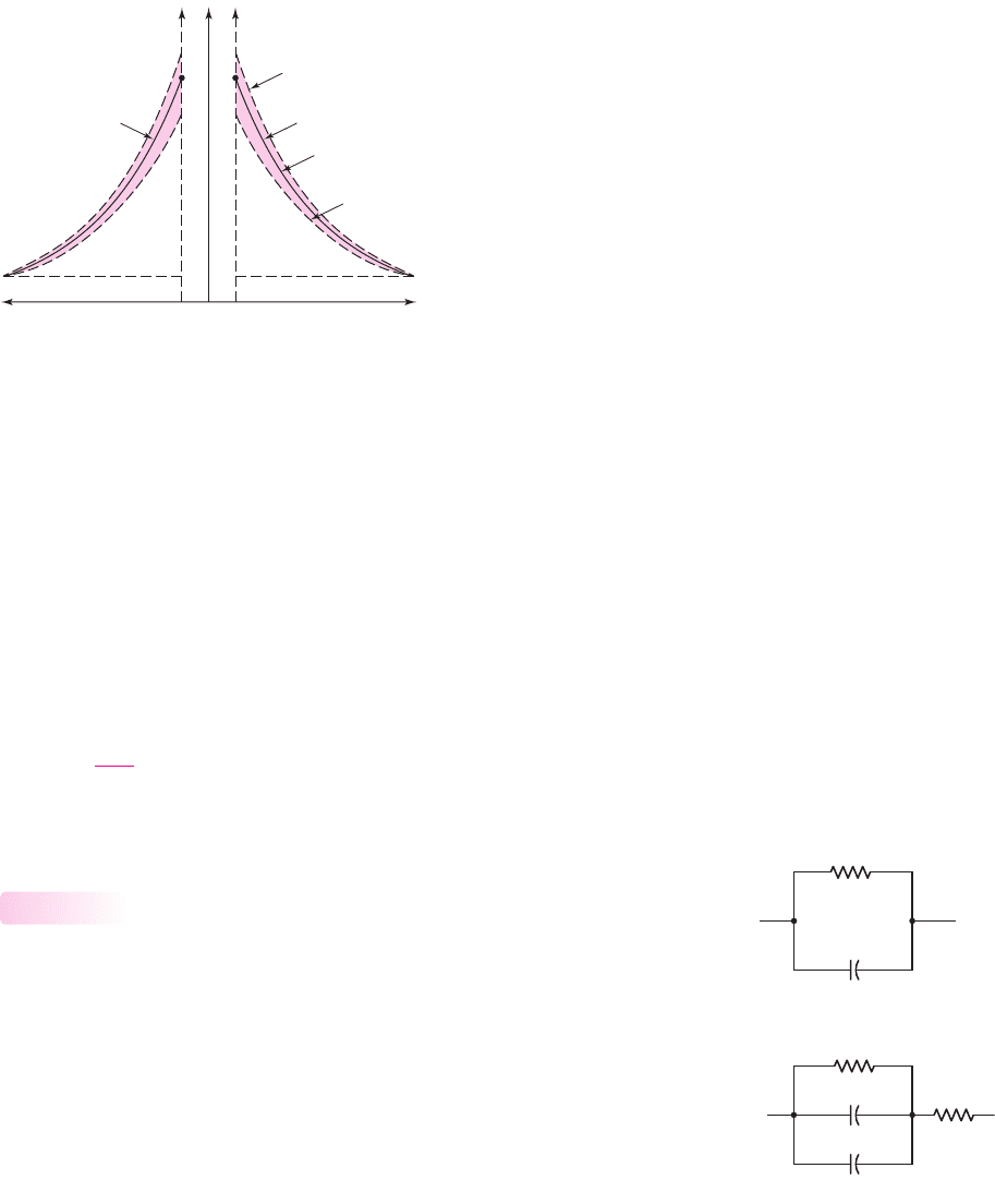
itance is shown in Figure 1.37.
Consider the minority carrier hole concentration on the right side of the figure.
At the quiescent diode voltage,
V
DQ
, the minority carrier hole concentration is shown
as the solid line and indicated by
p
n|V
DQ
.
nea80644_ch01_07-066.qxd 06/08/2009 05:15 PM Page 46 F506 Tempwork:Dont' Del Rakesh:June:Rakesh 06-08-09:MHDQ134-01 Folder:MHDQ134-01:
Chapter 1 Semiconductor Materials and Diodes 47
If the total diode voltage increases by
V during the positive half cycle of a
sinusoidal signal superimposed on the quiescent value, the hole concentration will in-
crease to that shown by the dotted line indicated by
p
n|V
DQ
+V
. Now, if the total diode
voltage decreases by
V
during the negative half cycle of a sinusoidal signal superim-
posed on the quiescent value, the hole concentration will decrease to that shown by the
dotted line indicated by
p
n|V
DQ
−V
. The
+Q
charge is alternately being charged and
discharged through the pn junction as the voltage across the junction changes.
The same process is occurring with the minority carrier electrons in the p-region.
The diffusion capacitance is the change in the stored minority carrier charge that
is caused by a change in the voltage, or
C
d
=
dQ
dV
D
(1.33)
The diffusion capacitance
C
d
is normally much larger than the junction capacitance
C
j
, because of the magnitude of the charges involved.
Small-Signal Equivalent Circuit
The small-signal equivalent circuit of the forward-biased pn junction is shown in
Figure 1.38 and is developed partially from the equation for the admittance, which
is given by
Y = g
d
+ jωC
d
(1.34)
where
g
d
and
C
d
are the diffusion conductance and capacitance, respectively. We
must also add the junction capacitance, which is in parallel with the diffusion resis-
tance and capacitance, and a series resistance, which is required because of the finite
resistances in the neutral n- and p-regions.
The small-signal equivalent circuit of the pn junction is used to obtain the ac
response of a diode circuit subjected to ac signals superimposed on the Q-point
values. Small-signal equivalent circuits of pn junctions are also used to develop
small-signal models of transistors, and these models are used in the analysis and
design of transistor amplifiers.
1.4.2
p
n
n
p
xx xx'
p-region
0 0
n-region
–ΔQ
+ΔQ
p
n|V
DQ
+ΔV
p
n|V
DQ
–ΔV
p
n|V
DQ
Figure 1.37 Change in minority carrier stored charge with a time-varying voltage
superimposed on a dc quiescent diode voltage. The change in stored charge leads to a diode
diffusion capacitance.
r
d
C
d
r
d
r
s
C
j
C
d
(a)
(b)
Figure 1.38 Small-signal
equivalent circuit of the
diode: (a) simplified version
and (b) complete circuit
nea80644_ch01_07-066.qxd 06/08/2009 05:15 PM Page 47 F506 Tempwork:Dont' Del Rakesh:June:Rakesh 06-08-09:MHDQ134-01 Folder:MHDQ134-01: