Simmons C.H., Dennis E.M. Manual of Engineering Drawing
Подождите немного. Документ загружается.

290 Manual of Engineering Drawing
• Risk assessment, including risk analysis and
evaluation
• Risk treatment, impact mitigation and probability
reduction
• Review and monitoring
• Communication (including consultation)
• Learning from the project
Guidelines are also provided on the organizational
requirements for implementing the process of risk
management appropriate to the various phases of a
project.
BS 8888:2002 on CD-ROM
Contains BS 8888:2002 and the full set of 114 cross-
referenced documents.
• 114 publications on one disk, accessible at the click
of a button
• A complete and comprehensive collection of all
cross-referenced documents
• A concise route-map to the complex web of ISO
standards within this area
Details regarding content and current prices can be
obtained from the BSI Information Customers Services,
389 Chiswick High Road. London W4 4AL website:
www.bsi-global.com/bsonline Tel: +44(0)20 8996 9001.
Email: orders@bsi-global.com
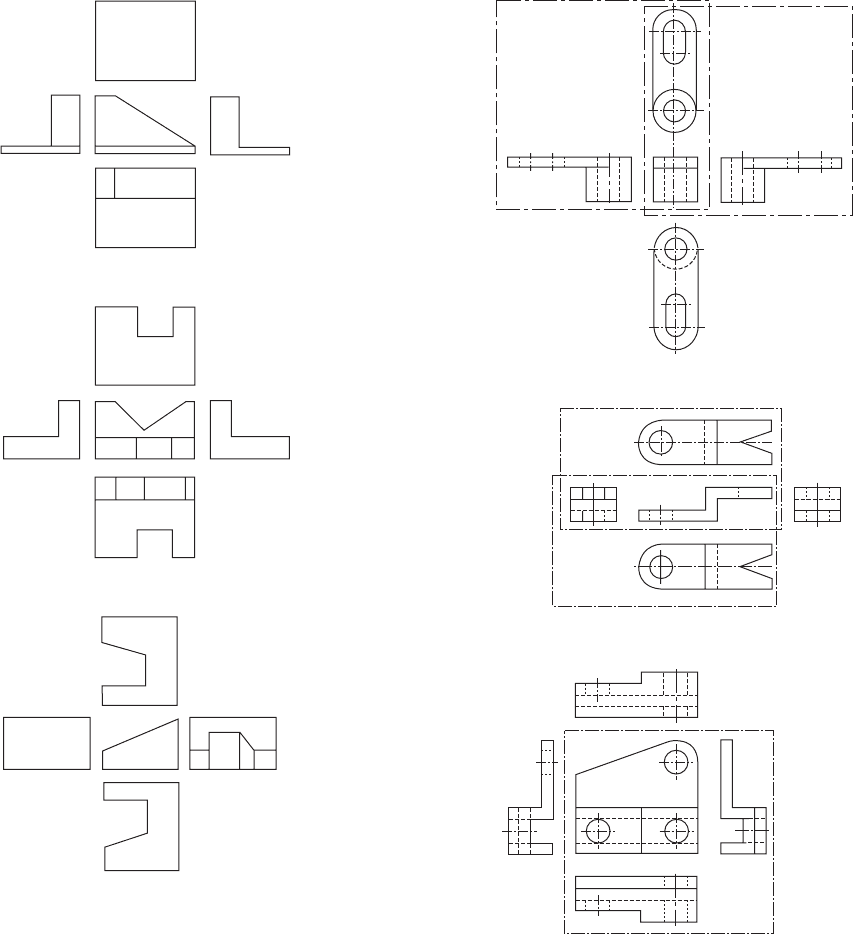
Chapter 32
Drawing solutions
(a)
(b)
(c)
(a)
(b)
(c)
1. Solutions to Fig. 4.17
2. Solutions to Fig. 4.18
292 Manual of Engineering Drawing
(a)
(b)
(c)
(a)
(b)
(c)
3. Solutions to Fig. 4.19
4. Solutions to Fig. 4.20
Drawing solutions 293
(a)
(b)
(c)
(d)
(a)
(b)
(c)
(d)
(e)
(f)
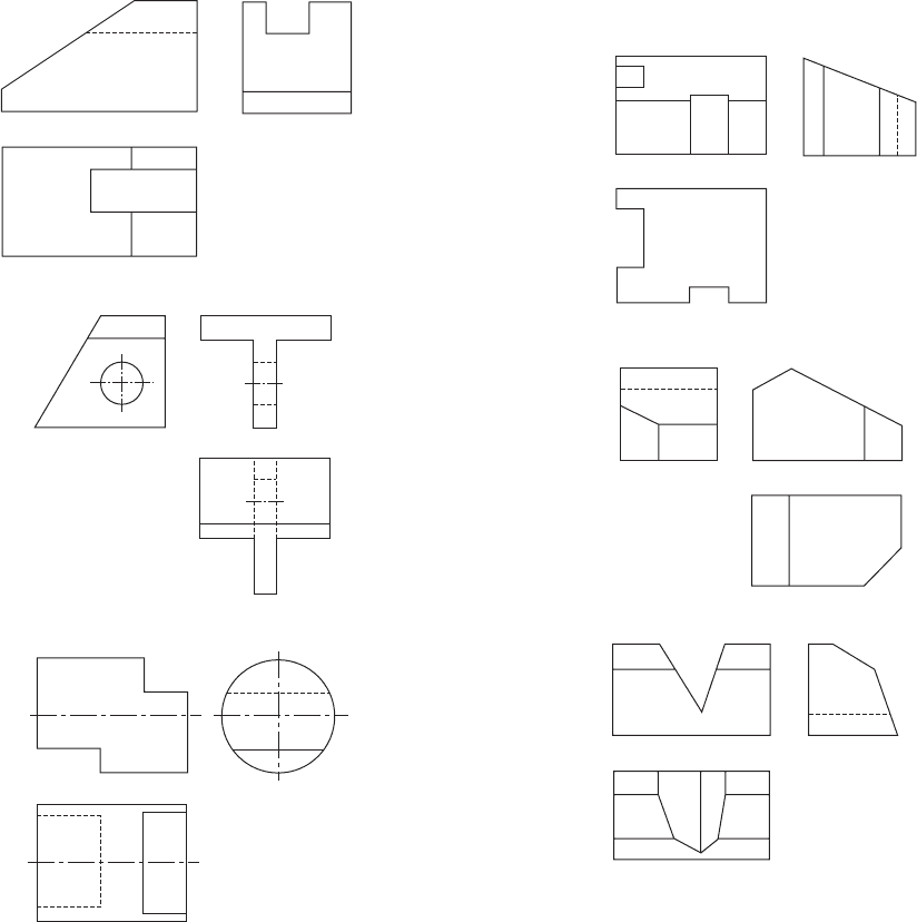
5. Solutions to Fig. 4.22
6. Solutions to Fig. 4.23
294 Manual of Engineering Drawing
(a)
(b)
(c)
A–A
A
A
A–A
A–A
(c)
A
A
A
A
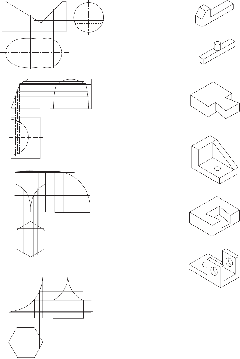
7. Solutions to Fig. 4.24
8. Solutions to Fig. 4.25
(a)
(b)
Drawing solutions 295
R30
R20
70
35
15
5
3
(a)
30
10
10
2 holes ø5
30 30 20
3 holes ø10
50
40
10
10
20
5
120
(b)
ø40
ø30
ø20
ø60
70
70
65
50
10
(c)
10
R10
40
ø10
ø20
10
15
30
25 35
100
(d)
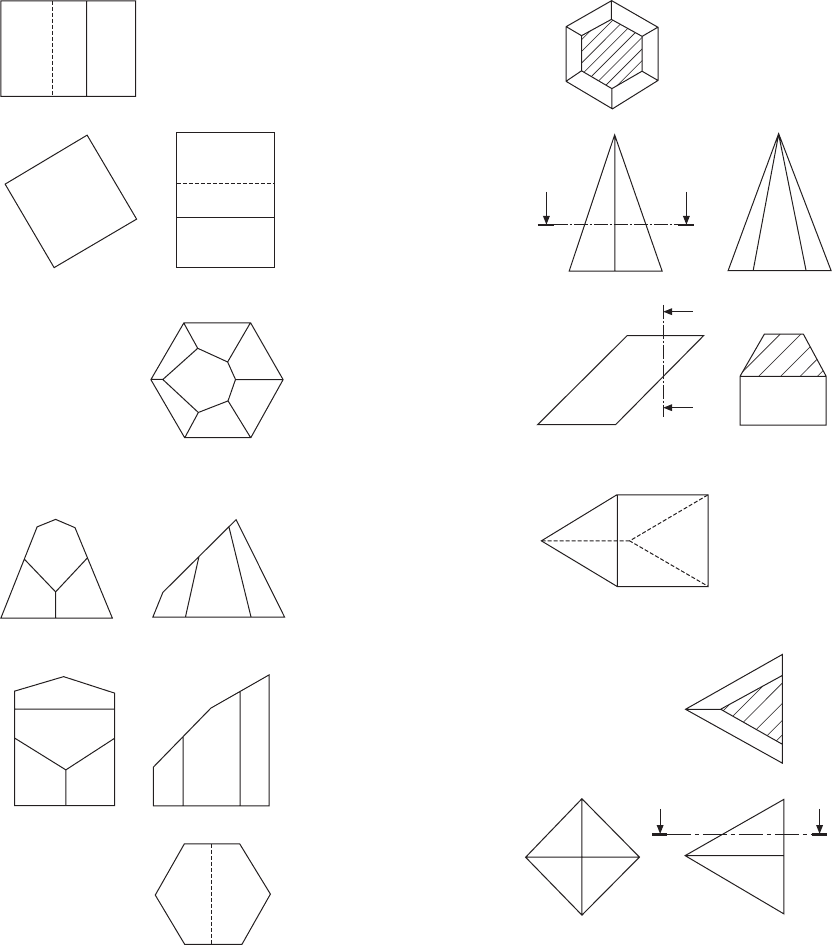
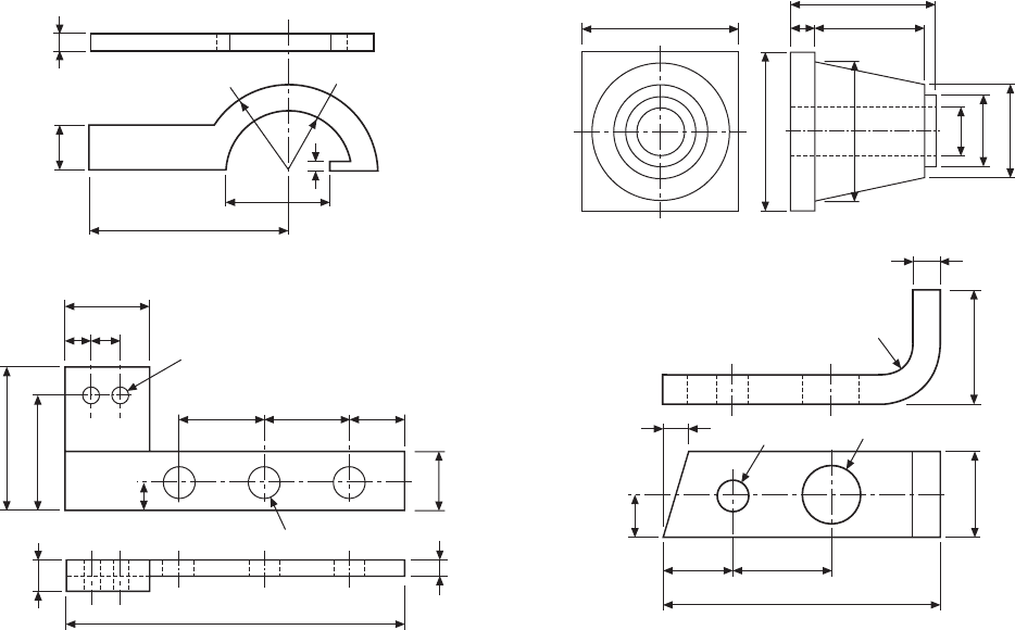
9. Solutions to Fig. 4.26
Index
Application of geometrical tolerances
168
straightness 168
flatness 169
circularity 169
cylindricity 170
profile of a line 170
profile of a surface 171
parallelism 171–2
perpendicularity (squareness) 172–3
angularity 173–4
circular run-out 174–5
total run-out 175
position 175–6
concentricity and coaxiality 177
symmetry 177–8
Bearings 249
angular contact 255
application 257
ball bearing 255
ball and roller 251
combined seals 261
conventional representation 263
cylindrical roller bearings 256
deep groove ball 255
lubrication 262
axial location 259
fits and tolerances 259
methods of location 259
with cylindrical bore 257
with tapered bore 259
needle roller 256
non rubbing seals 260
plain bearings 249–50
rubbing seals 261
self-aligning 255
spherical roller 256
taper roller 256
thrust ball 257
structural bearings 250
CAD organization and applications 13
Auto CAD 2002 14
Auto CAD LT 2002 15
Auto CAD mechanical 14
Auto CAD inventor series 15
Architectural desktop 33 15
Autodesk VIZ 4 15
Piranesi 15
Navis Works 15
Autodesk raster design 3 15
Auto sketch 15
project development 16
parametric design 17
sheet metal application 19
pipework systems 20
communicating design concepts 21
typical Auto CAD drawings 21–32
Cams and gears 190
cam followers 190
cam follower motion 190
dimensioning cams 195
cylindrical cam 194
face cam 191
plate cam 193
simple harmonic motion 191
uniform acceleration and retardation
191
uniform velocity 191–2
Conic sections and interpenetration of
solids 87
ellipse 87
parabola 87
hyperbola 88
interpenetration of solids 89
cylindrical and conical applications
89–92
Developments 93
edge finishes 93
hexagonal prism 93–4
hexagonal pyramid 97
elbow development 93–4
oblique cones 97
transition piece rectangular 98
transition pieces square to round 99
thin lamina 95
truncated cone 96
truncated square pyramid 96
triangular prism 98
Dimensioning principles 100
angular dimensions 104
chain dimensioning 102
chamfers 106
circles 102–3
counterbores 106–7
countersinks 107–8
curves 103–4
flats 106
general rules 100–1
holes 106
irregular curves 103–4
graphical symbols to indicate surface
texture 109–13
dimensioning for manufacture 108
dimensions not to scale 102
parallel dimensioning 102
radii 103
spherical radii and diameters 103
staggered dimensions 102–3
squares 106
spotfaces 107–8
tapers 104–6
undirectional and aligned dimensions
104
Drawing layouts and simplified methods
54
assembly drawings 54
combined detail and assembly
drawings 56
collective assembly drawings 56
abbreviations 63
exploded assembly drawings 57
single part drawing 54
simplified drawings 57
machine drawing terminology 59–61
drawing scales 61–3
design layout drawing 56
collective single part drawing 54
Drawing office management and
organization 1–4
engineering drawing practices 4
drawing practice and the computer 4
Drawing solutions 191–5
Engineering diagrams 214
relevant standards 214
types of diagrams 216
electrical and electronic symbols 215
electronic diagrams 216
vehicle wiring 217–8
heating ventilation and air conditioning
218
ventilation system 227
air conditioning systems 227–8
building management 229
psychrometric charts 229
refrigeration systems 232–5
pneumatic systems 235
air compressor installation 235
fluid power symbols 237
pneumatic circuit design 236
Engineering adhesives 264
bonded joints 265–7
engineering applications 267
instant adhesives 266
structural applications 270
Geometrical constructions and tangency
68
basic geometry 68–70
tangency applications 70–2
Geometrical tolerancing and datums 160
advantages and rules 160
application of tolerance frames 163
restricted tolerances 163
datums 164
datum targets 166
datum features 166
methods of indication 162
non-rigid parts 167
positioning of related remarks 163
projected tolerance zone 164
symbols and applications 161–2
theoretically exact dimensions 160
tolerance zones 164
Gears 195
bevel gears 198
conventions and proportions 196
helical gears 197
involute construction 195
rack and pinion 197–8
spur gears 195
298 Index
spur gear terms 195–6
Unwin’s construction 196–7
worm gearing 200–1
Keys and keyways 134
examples
square parallel key 134
gib-head key 134
edge-milled keyway 134
end-milled keyway 134
keyway in hub 134
sunk keys 134
rectangular 135
square 135
square tapered 135
gib-head 135
double headed feather 135
peg feather 135
feather 135
woodruff keys 135–6
round key 136
saddle key 136
dimensioning keyways 136
Limits and fits 153
bilateral limits 155
clearance fit 154
hole, basis fits 155
interference fits 154
ISO fits hole basis 157
ISO fits shaft basis 158
interpretation of limits of size in
relation to form 156
the principle of independency 156,
159
the envelope requirement 156 159
transition fit 154
terminology 155
unilateral limits 155
Linework and lettering 45
types of line 46
chain lines 46
ISO ‘A’ series paper 45
lettering 48
drawing modifications 49
care and storage of drawings 49
Loci applications 73
archimedean spiral 75
conical helix RH 77
cycloid 77
cylindrical helix RH 75
epicycloid 77
ellipse 73
ellipse 2 circle method 73
ellipse foci methods 74
ellipse trammel methods 73
hypocycloid 78
involute 75
square section helical spring 76
single start square thread 77
shaper mechanism 79
Watt’s straight line motion 80
toggle action 81
Maximum material and least material
principles 179
max and least material condition 179
MMC applications
geometrical form 179
straightness 180
squareness 180
position 181
coaxiality 181
perfect forms 182–4
mating components 184–5
Nuts, bolts, screws and washers 120
drawing nuts and bolts 120–1
standard dimensions 122
approximate constructions 121–2
standard screws 122–7
machine screw nuts 127
wing nuts 127
locking devices 128
thread cutting screws 132
Positional tolerancing 186
True position [theorectical exact]
dimensioning 186
Positional tolerancing in two directions
187
Circular tolerance 187
Rectangular tolerance 187
Square and coaxial 188
Circular group of features 188–9
Pattern of Features 189
Principles of first and third angle
projection 33
first angle projection 33
drawing procedure 36
projection symbols 35
reading engineering drawings 36
projection exercises 38
third angle projection 34
Product development and computer aided
design 7
computer aided design 8
Technical product documentation
(TPD) 10
computer access 11
quality assurance 11–12
Production drawings 287
examples 282–90
Related standards 272
the British Standards Inst. 272
the making of standards 273
International Organization for
Standardization [ISO] 273
development of international standards
274–5
origin of international standards 274
ISO membership 275–81
Sections and sectional views 64
half sections 65
hatching 65
removed sections 66
revolved sections 65
thin material sections 66
two parallel planes 67
successive sections 67
local sections 66
sectioning conventions 67
Screw threads and conventional
representations 114
acme 117
British association 117
buttress 117
LH and RH thread 114
ISO metric threads 114–16
sellers 116
square 117
terminology 114
unifed 116
whitworth 116
multiple threads 119
draughting conventions 117–8
British standard pipe 116
Springs 202
compression 203
specifications 208
spring materials 202
corrosion prevention 209
fatigue conditions 209
disc springs 207
helical extension springs 205
flat springs 203
leaf springs 205
torsion springs 205
wire forms 209
Three dimensional illustrations using
isometric and oblique projections
50
oblique projection 51
isometric projection 50
True lengths and auxiliary views 82
examples 82–86
Welding and welding symbols 210
dimensioning of welds 213
elementary weld symbols 211
supplementary symbols 212
drawing examples of welds 212
Worked examples in machine drawing 137
air engine 140
bushed bearing bracket 138
cam operated clamp 140
drill table 138
plug cock 140
toolbox 145
solutions and notes 147–152