Yu W., LaBoube R.A. Cold-Formed Steel Design
Подождите немного. Документ загружается.

DESIGN BASIS 55
moment, shear force, etc.) on the cross section determined
from the structural analysis and γ
i
are the corresponding
load factors that account for the uncertainties and variabili-
ties of the applied loads. The load factors are usually greater
than unity, as given in Section 3.3.2.2.
For the design of cold-formed members using carbon
and low-alloy steels, the values of φ and R
n
are given in
the main body of the North American Specification and
Appendix 1.
1.345
3.3.2.2 Nominal Loads, Loads Factors, and Load
Combinations for the LRFD Method The design provi-
sions for nominal loads and load combinations are provided
in Appendix A of the North American Specification for use
in the United States and Mexico. The following discussion
is applicable only to the LRFD method:
(a) Nominal Loads. The design requirements for nominal
loads to be used for the LRFD method are the same as
that used for the ASD method. See item (a) of Section
3.3.1.2 for the discussion based on Section A3.1 of
Appendix A of the North American Specification.
(b) Load Factors and Load Combinations for LRFD.
Section A5.1.2 of Appendix A of the North American
Specification specifies that the structure and its compo-
nents shall be designed so that design strengths equal
or exceed the effects of the factored loads and load
combinations stipulated by the applicable building
code under which the structure is designed or, in the
absence of an applicable building code, as stipulated
in the ASCE Standard, Minimum Design Loads for
Buildings and Other Structures, ASCE/SEI 7.
When the ASCE Standard is used for the LRFD method,
the following load factors and load combinations should be
considered for the strength limit state
3.201
:
1. 1.4(D + F) (3.5a)
2. 1.2(D + F + T)+ 1.6(L + H)+ 0.5(L
r
or S or R)
(3.5b)
3. 1.2D + 1.6(L
r
or S or R) + (L or 0.8W) (3.5c)
4. 1.2D + 1.6W + L + 0.5(L
r
or S or R) (3.5d)
5. 1.2D + 1.0E + L + 0.2S (3.5e)
6. 0.9D + 1.6W + 1.6H (3.5f)
7. 0.9D + 1.0E + 1.6H (3.5g)
All the symbols are defined in item (b) of Section 3.3.1.2.
For the above load combinations, exceptions are as follows:
1. The load factor on L in combinations (3), (4), and
(5) is permitted to equal 0.5 for all occupancies in
which the minimum uniformly distributed live load
L
0
in Table 4-1 of ASCE/SEI 7
3.201
is less than or
equal to 100 psf, with the exception of garages or areas
occupied as places of public assembly.
2. The load factor on H shall be set equal to zero in
combinations (6) and (7) if the structural action due
to H counteracts that due to W or E. Where lateral
earth pressure provides resistance to structural actions
from other forces, it shall not be included in H but
shall be included in the design resistance.
3. In combinations (2), (4), and (5), the load S shall be
taken as either the flat-roof snow load or the sloped-
roof snow load.
Each relevant strength limit state shall be investigated.
Effects of one or more loads not acting shall be investi-
gated. The most unfavorable effects from both wind and
earthquake loads shall be investigated, where appropriate,
but they need not be considered to act simultaneously.
For the serviceability limit state, Appendix B of Ref.
3.201 contains the suggested load combinations.
Because building codes and the ASCE Standard do
not provide load factors and load combinations for roof
and floor composite construction using cold-formed steel
deck, the following load combination is included in the
Commentary on the North American Specification for this
type of composite construction
1.346
:
1.2D
s
+ 1.6C
w
+ 1.4C (3.6)
where D
s
= weight of steel deck
C
w
= weight of wet concrete during construction
C = construction load, including equipment,
workmen, and formwork but excluding
weight of wet concrete
The above load combination provides safe construction
practices for cold-formed steel decks and panels that other-
wise may be damaged during construction. The load factor
used for the weight of wet concrete is 1.6 because delivering
methods are such that an individual sheet can be subjected
to this load. The use of a load factor of 1.4 for the construc-
tion load is comparable to the allowable strength design
method.
3.3.2.3 Design Strength φR
n
The design strength is the
available strength of a structural component or connection
to be used for design purposes. As shown in Eq. (3.4),
design strength is obtained by multiplying the nominal
strength or resistance R
n
by a reduction factor φ to
account for the uncertainties and variabilities of the nominal
strength.

56 3 STRENGTH OF THIN ELEMENTS AND DESIGN CRITERIA
Nominal Strength or Resistance R
n
. The nominal
strength or resistance R
n
is the capacity of a structural
component or connection to resist load effects (axial force,
bending moment, shear force, etc.). It is usually determined
by computations using specified material properties and
dimensions in the design criteria derived from accepted
principles of structural mechanics a nd/or by tests, taking
account of the effects of manufacturing and fabrication
processes. For the design of cold-formed members using
carbon and low-alloy steels, Chapters C through G of the
North American Specification
1.345
provide the equations
needed for determining the nominal strengths of tension
members, flexural members, compression members, closed
cylindrical tubular members, wall studs, connections,
and joints. It should be noted that for the purpose of
consistency the same nominal strength equations are used
in the North American specification for the ASD and
LRFD methods.
1.345
In 2004, the DSM was added in the North American
Specification as Appendix 1. This method can be used
to determine the axial strengths of columns and flexural
strengths of beams subjected to the specified geometric and
material limitations.
1.343
Resistance Factor φ. The resistance factor φ is a reduc-
tion factor to account for unavoidable deviations of the
actual strength from the nominal value prescribed in the
design specification. These deviations may result from the
uncertainties and variabilities in (1) the material proper-
ties (i.e., yield stress, tensile strength, modulus of elasticity,
etc.), (2) the geometry of the cross section (i.e, depth, width,
thickness, etc., to be used for computing area, moment
of inertia, section modulus, radius of gyration, etc.), and
(3) the design methods (i.e., assumptions, approximations
of theoretical formulas, etc.).
In the development of the AISI LRFD criteria,
3.159
the
resistance factors were derived from a combination of
(1) probabilistic modeling,
3.160,3.161
(2) calibration of the
new criteria to the ASD approach,
3.162
and (3) evaluations
of the new LRFD criteria by judgment and past experience.
The development was aided by a comparative study of the
ASD and LRFD methods.
3.157,3.163
The procedures used
for developing the resistance factors for cold-formed steel
design consisted of the following five steps:
1. Analyze the available information and test data to
obtain the statistical value (mean values and coeffi-
cients of variation) of resistance and load effects.
2. Assume the mean values and coefficients of variation
of the variable for which no statistical information is
available.
3. Compute the reliability index implied in the applicable
ASD specification.
4. Select the target reliability index.
5. Develop the resistance factors according to the
selected target reliability index for different types of
members with the limit state being considered.
Details of steps 1, 2, and 3 are presented in several progress
reports of the University of Missouri-Rolla and are summa-
rized in Ref. 3.162. Based on the probability distribution
shown in Fig. 3.8 and the first-order probabilistic theory, the
reliability index β can be computed by Eq. (3.7)
1.248,3.152
:
β =
ln
(
R
m
/Q
m
)
V
2
R
+ V
2
Q
(3.7)
where R
m
= mean value of resistance
= R
n
(P
m
M
m
F
m
)
Q
m
= mean value of load effect
Figure 3.8 Definition of reliability index.

DESIGN BASIS 57
V
R
= coefficient of variation of resistance,
=σ
R
/R
m
=
V
2
P
+ V
2
M
+ V
2
F
V
Q
= coefficient of variation of load effect,
=σ
Q
/Q
m
σ
R
= standard deviation of resistance
σ
Q
= standard deviation of load effect
P
m
= mean ratio of experimentally determined
ultimate load to predicted ultimate load of
test specimens
M
m
= mean ratio of tested material properties to
specified minimum values
F
m
= mean ratio of actual sectional properties to
nominal values
V
P
= coefficient of variation of ratio P
V
M
= coefficient of variation of ratio M
V
F
= coefficient of variation of ratio F
The reliability index β is a measure of the safety of the
design. As shown in Fig. 3.8, a limit state is reached when
ln(R/Q) = 0. The s haded area represents the probability
of exceeding the limit states. The smaller the shaded area
is, the more reliable the structure is. Because the distance
between the mean value of [ln(R/Q)]
m
and the failure region
is defined as β[σ
ln(R/Q)
], when two designs are compared,
the one with the larger β is more reliable.
As far as the target reliability index β
0
is concerned,
research findings indicated that for cold-formed steel
members the target reliability index may be taken as
2.5 for gravity loads. In order to ensure that failure of a
structure is not initiated in connections, a higher value of
3.5 was selected for connections using cold-formed carbon
steels. Even though these two target values are somewhat
lower than those recommended by the ASCE code (i.e., 3.0
and 4.5 for members and connections, respectively),
3.149
they are essentially the same targets used for the AISC
LRFD Specification.
3.150
For wind loads, the same ASCE
target value of β
0
= 2.5 is used for connections in the
LRFD method. For flexural members such as individual
purlins, girts, panels, and roof decks subjected to the
combination of dead and wind loads, the target β
0
value
used in the United States is reduced to 1.5. With this
reduced target reliability index, the design based on the
LRFD method is comparable to the allowable strength
design method.
On the basis of the load combination of 1.2D + 1.6L
with an assumed D/L ratio of
1
5
and the available statistical
data, it can be shown that the resistance factor φ can be
determined as follows
1.310
:
φ =
1.521M
m
F
m
P
m
exp
β
0
V
2
R
+ V
2
Q
(3.8)
where β
0
is the target reliability index. For practical
reasons, it is desirable to have relatively few different resis-
tance factors. Table 3.1 lists the resistance factors for the
design of various types of members and c onnections using
carbon and low-alloy steels.
If the φ factor is known, the corresponding safety factor
for allowable strength design can be computed for the
load combination 1.2D + 1.6L as follows
1.310
:
=
1.2D/L + 1.6
φ
(
D/L + 1
)
(3.9)
where D/L is the dead-to-live load ratio for the given
condition.
3.3.3 Limit States Design
The LSD method is currently used in Canada for the
design of cold-formed steel members, connections, and
structural assemblies. The methodology for the LSD and
LRFD methods is the same, except that load factors, load
combinations, target reliability indexes, and the assumed
dead-to-live ratio used for the development of the design
criteria are different. As a result, the resistance factors used
for the LSD method are usually slightly smaller than that
for the LRFD method in the main document of the North
American Specification.
The design provisions for the LSD method are provided
in Section A6 of the North American Specification supple-
mented by the additional information on load factors and
load combinations in Appendix B. For the LSD method,
a few different terms are defined in Section A1.3 of the
North American Specification. Table 3.2 lists some equiv-
alent terms used for the LRFD and LSD methods.
3.3.3.1 Design Format for the LSD Method According
to Section A6.1.1 of the North American Specification
for LSD requirements, structural members and connections
shall be designed such that the factored resistance equals
or exceeds the effect of factored loads. The design s hall be
Table 3.2 Equivalent Terms for the LRFD and LSD
Methods
LRFD (U.S. and Mexico) LSD (Canada)
Design strength, φR
n
Factored resistance, φR
n
Flexural strength Moment resistance
Nominal load Specified load
Nominal strength, R
n
Nominal resistance, R
n
Required strength, R
u
Effect of factored loads, R
f
Specification Standard
Strength Resistance
58 3 STRENGTH OF THIN ELEMENTS AND DESIGN CRITERIA
performed in accordance with the following equation
1.345
:
φR
n
≥ R
f
where R
f
= effect of factored loads
R
n
= nominal resistance
φ = resistance factor (see Table 3.1)
φR
n
= factored resistance
The above equation for the LSD method is similar to
Eq. (3.4) for the LRFD method.
3.3.3.2 Specified Loads, Load Factors, and Load Combi-
nations for LSD Method The design requirements for
specified loads, load factors, and load combinations are
provided in Appendix B of the North American specifica-
tion. The following discussions are applicable only to the
LSD method for use in Canada. All design tables referred
in items (b) and (c) are based on Appendix B of the 2007
edition of the Specification
1.345
:
(a) Specified Loads. The load provisions contained in the
North American Specification were revised in 2004
1.343
for consistency with the 2005 edition of the National
Building Code of Canada. Based on Section A3.1 of
Appendix B, the following loads, forces, and effects
shall be considered for the design of cold-formed steel
structural members and their connections:
D = dead load
E = earthquake load
H = permanent load due to lateral earth pressure,
including groundwater pressure
L = live load
S = snow load, including ice and associated rain,
or rain
T = effect due to contraction, expansion, or deflection
caused by temperature changes, shrinkage,
moisture changes, creeps, temperature, ground
settlement, or c ombinations thereof
W = wind load
(b) Load Factors and Load Combinations for LSD.
According to Section A6.1.2 of Appendix B, the effect
of factored loads for cold-formed steel design should
be determined on the basis of the applicable load
combinations listed in Table A6.1.2-1. Appropriate
load factors shall be used for principal and companion
loads.
(c) Importance Categories and Importance Factor (I).
For the purpose of determining specified loads S,
W, or E, buildings shall be assigned an importance
category (low, nominal, high, or postdisaster) from
Table A6.1.2.1-1 based on intended use and occu-
pancy. The importance factor used for snow, wind,
and earthquake can be selected from Table A6.1.2.2-1
for the assigned important category.
3.3.3.3 Factored Resistance R
n
In the development
of the LSD criteria, the resistance factors were determined
from a live-load factor of 1.50 and a dead-load factor of
1.25 according to the National Building Code of Canada.
The target safety indexes are 3.0 for members and 4.0
for connections. In order to determine the loading for
calibration, it was assumed that 80% of cold-formed steel
is used in panel form and 20% for structured members.
An effective load factor was arrived at by a ssuming the
live-to-dead load ratio and their relative frequencies of
occurrence. For nominal resistance R
n
see Section 3.3.2.3.
The same nominal resistance equations are used in the
main document of the North American specification for
the ASD, LRFD, and LSD methods with specific Canadian
design requirements provided in Appendix B of the North
American Specification for some cases.
3.3.3.4 Design U sing the LSD Method Even through
the load factors, load combinations, and resistance factors
for the LSD method are somewhat different as compared
with LRFD, the methodology and design procedures for
these two methods are the same. For the purpose of
simplicity, the discussions and design examples presented
in this book are based on the ASD and LRFD methods.
The design procedures for the LRFD method can be
used for the LSD method with appropriate terms and φ
factors.
3.3.4 Units of Symbols and Terms
The North American Specification was written so that any
compatible system of units may be used except where
explicitly stated in the document. The unit systems adopted
in the North American Specification are:
1. U.S. customary units (force in kilopounds or kips and
length in inches)
2. SI units (force in newtons and length in millimeters)
3. MKS units (force in kilograms and length in
centimeters)
The conversions of the U.S. customary units into SI units
and MKS units are given in parentheses throughout the text
of the Specification. Table 3.3 is a conversion table for these
units.
For the purpose of simplicity, only U.S. customary units
are used in this book for design examples.

STRUCTURAL BEHAVIOR OF COMPRESSION ELEMENTS AND DESIGN CRITERIA 59
Table 3.3 Conversion Table
1.346
To Convert To Multiply By
Length in. mm 25.4
mm in. 0.03937
ft mm 0.30480
mft3.28084
Area in.
2
mm
2
645.160
mm
2
in.
2
0.00155
ft
2
m
2
0.09290
m
2
ft
2
10.7639
Force kip kN 4.448
kip kg 453.5
lb N 4.448
lb kg 0.4535
kN kip 0.2248
kN kg 101.96
kg kip 0.0022
kg N 9.808
Stress ksi MPa 6.895
ksi kg/cm
2
70.30
MPa ksi 0.145
MPa kg/cm
2
10.196
kg/cm
2
ksi 0.0142
kg/cm
2
MPa 0.0981
3.4 SERVICEABILITY
Section 3.3 dealt only with the strength limit state. A struc-
ture should also be designed for the serviceability limit state
as required by Section A8 of the AISI Specification.
1.345
Serviceability limit states are conditions under which
a structure can no longer perform its intended functions.
Strength considerations are usually not affected by service-
ability limit states. However, serviceability criteria are
essential to ensure functional performance and economy
of design.
The conditions which may require serviceability limits
are listed in the AISI Commentary as follows
1.310,1.346
:
1. Excessive deflections or rotations which may affect
the appearance or functional use of the structure and
deflections which may cause damage to nonstructural
elements
2. Excessive vibrations which may cause occupant
discomfort of equipment malfunctions
3. Deterioration over time, which may include corrosion
or appearance considerations
When checking serviceability, the designer should
consider appropriate service loads, the response of the
structure, and the reaction of building occupants.
Service loads that may require consideration include
static loads, snow or rain loads, temperature fluctuations,
and dynamic loads from human activities, wind-induced
effects, or the operation of equipment. The s ervice loads are
actual loads that act on the structure at an arbitrary point in
time. Appropriate service loads for checking serviceability
limit states may only be a fraction of the nominal loads.
The response of the structure to service loads can
normally be analyzed assuming linear elastic behavior.
Serviceability limits depend on the function of the structure
and on the perceptions of the observer. Unlike the strength
limit states, general serviceability limits cannot be speci-
fied that are applicable to all structures. The North Amer-
ican Specification does not contain explicit requirements;
however, guidance is generally provided by the applicable
building code. In the absence of specific criteria, guidelines
may be found in Refs. 3.164–3.167 and 3.202–3.206.
3.5 STRUCTURAL BEHAVIOR OF
COMPRESSION ELEMENTS AND DESIGN
CRITERIA
3.5.1 Stiffened Compression Elements
3.5.1.1 Stiffened Elements under Uniform Compression
Yielding. The strength of a stiffened compression element
such as the compression flange of a hat section is governed
by yielding if its w/t ratio is relatively small. It may be
governed by local buckling a s shown in Fig. 3.9 at a stress
level less than the yield stress if its w/t ratio is relatively
large.
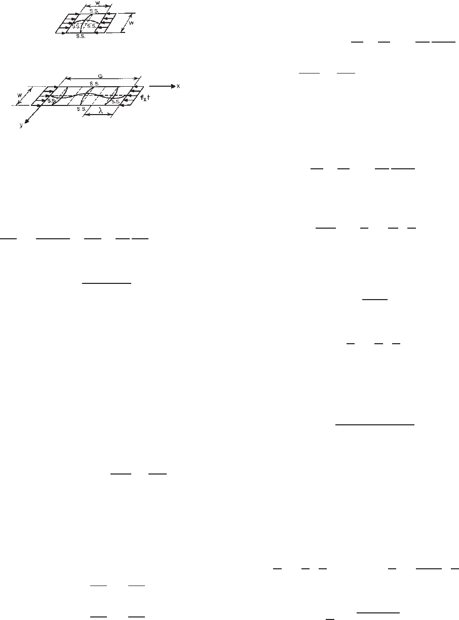
Elastic Local Buckling Stress of Plates. Considering
a simply supported square plate subjected to a uniform
compression stress in one direction, it will buckle in a
single curvature in both directions, a s shown in Fig. 3.10.
However, for individual elements of a section, the length
of the element is usually much larger than the width, as
illustrated in Fig. 3.9.
Figure 3.9 Local buckling of stiffened compression flange of
hat-shaped beam.
1.161
60 3 STRENGTH OF THIN ELEMENTS AND DESIGN CRITERIA
Figure 3.10 Square plate subjected to compression stress.
Figure 3.11 Rectangular plate subjected to compression stress.
The critical buckling stress of a plate as shown in
Fig. 3.11 can be determined by solving Bryan’s differential
equation based on small-deflection theory (i.e., the signifi-
cant deflection at buckling is of the order of the thickness
of the plate or less) as follows:
∂
4
ω
∂x
4
+ 2
∂
4
ω
∂x
2
∂y
2
+
∂
4
ω
∂y
4
+
f
x
t
D
∂
2
ω
∂x
2
= 0 (3.10)
where
D =
Et
3
12
1 − μ
2
and E = modulus of elasticity of steel, =29.5 ×10
3
ksi
(203 GPa or 2.07 ×10
6
kg/cm
2
)
t = thickness of plate
μ = Poisson’s ratio, =0.3 for steel in the elastic
range
ω = deflection of plate perpendicular to surface
f
x
= compression stress in x direction
If m and n are the numbers of half sine waves in the
x and y directions, respectively, the deflected shape of the
rectangular plate as shown in Fig. 3.11 may be represented
by a double series:
ω =
∞
m=1
∞
n=1
A
mn
sin
mπx
a
sin
nπy
w
(3.11)
The above equation is satisfied with boundary conditions
because for x = 0, a and y = 0, w (a and w being the
length and width of the plate, respectively) the computed
deflection equals zero. Since ∂
2
ω/∂x
2
= 0and∂
2
ω/∂y
2
=
0 at four edges, Eq. (3.11) also satisfies the condition that
the edge moments equal zero because
M
x
=−D
∂
2
ω
∂x
2
+ μ
∂
2
ω
∂y
2
M
y
=−D
∂
2
ω
∂y
2
+ μ
∂
2
ω
∂x
2
Solving Eq. (3.10) by using Eq. (3.11), one can then obtain
the equation
∞
m=1
∞
n=1
A
mn
π
4
m
2
a
2
+
n
2
w
2
2
−
f
x
t
D
m
2
π
2
a
2
× sin
mπx
a
sin
nπy
w
= 0 (3.12)
It is obvious that the solution can be obtained if either
A
mn
= 0 or the quantity in square brackets equals zero. The
former condition means that no buckling will occur, which
is not applicable to this particular case.
By solving
π
4
m
2
a
2
+
n
2
w
2
2
−
f
x
t
D
m
2
π
2
a
2
= 0
one can obtain an equation for critical local buckling stress
as follows:
f
cr
= f
x
=
Dπ
2
tw
2
m
w
a
+
n
2
m
a
w
2
(3.13)
In Eq. (3.13) the minimum value in square brackets
is n = 1, that is, only one half sine wave occurs in the
y direction. Therefore
f
cr
=
kDπ
2
tw
2
(3.14)
where
k =
m
w
a
+
1
m
a
w
2
(3.15)
Substituting the value of D in Eq. (3.14), Eq. (3.16)
represents a general equation for critical local buckling
stress for a rectangular plate subjected to compression stress
in one direction:
f
cr
=
kπ
2
E
12
1 − μ
2
(
w/t
)
2
(3.16)
The value of k used in Eq. (3.16) is shown in Fig. 3.12
for different a/w ratios.
It should be noted that when the a/w ratio is an integer
the value of k equals 4. This value of k is also applicable
for relatively large a/w ratios.
From Fig. 3.12 and Eq. (3.15) it can be seen that the
transition from m to m + 1 half sine waves occurs at the
condition when the two corresponding curves have equal
ordinates, that is,
m
w
a
+
1
m
a
w
=
(
m + 1
)
w
a
+
1
m + 1
a
w
or
a
w
=
m
(
m + 1
)

STRUCTURAL BEHAVIOR OF COMPRESSION ELEMENTS AND DESIGN CRITERIA 61
Figure 3.12 Buckling coefficient for flat rectangular plates.
3.1
For a long plate,
a
w
∼
=
m
or
λ =
a
w
∼
=
m (3.17)
where λ is the length of the half sine wave.
Equation (3.17) indicates that the number of half sine
waves increases with the increase of a/w ratios. For a long
plate, the length of the half sine waves equals approximately
the width of the plate, and therefore s quare waves are
formed, as shown in Fig. 3.11.
In structural engineering, the long plate having a rela-
tively large a/w ratio is of particular interest because such
a long plate often represents the case of individual elements
of the sections generally used in structures. As shown in
Fig. 3.12, whenever the aspect ratio a/w exceeds about 4,
a value of k = 4 can be used for determining the crit-
ical buckling stress for a plate simply supported along four
edges and subjected to compression stress in one direction,
that is,
f
cr
=
π
2
E
3
1 − μ
2
(
w/t
)
2
(3.18)
Equation (3.18) is also applicable to a square plate.
The values of k for a long rectangular plate subjected
to different types of stress (compression, shear, or bending)
and under different boundary conditions (simply supported,
fixed, or free e dge) are tabulated in Table 3.4.
Buckling of Plates in the Inelastic Range. When the
compression stress in a plate in only one direction exceeds
the proportional limit of the steel, the plate becomes an
anisotropic plate which has different properties in different
directions of the plate.
Table 3.4 Values of k for Determining Critical
Buckling Stress
3.2
f
cr
= k
π
2
E
12
1 − μ
2
(
w/t
)
2
Type of Value of k for
Case Boundary Condition Stress Long Plate
(a) Compression 4.0
(b)
Compression 6.97
(c)
Compression 0.425
(d)
Compression 1.277
(e)
Compression 5.42
(f)
Shear 5.34
(g)
Shear 8.98
(h)
Bending 23.9
(i)
Bending 41.8
In 1924 Bleich proposed the following differential
equation for inelastic buckling
3.3
:
τ
∂
4
ω
∂x
4
+ 2
√
τ
∂
4
ω
∂x
2
∂y
2
+
∂
4
ω
∂y
4
+
f
x
t
D
∂
2
ω
∂x
2
= 0 (3.19)
where τ = E
t
/E,andE
t
is the tangent modulus of steel.
Applying the modified boundary conditions, one can
then obtain the following critical buckling stress for plastic
buckling of the plate:
f
cr
=
kπ
2
E
√
τ
12
1 − μ
2
(
w/t
)
2
=
kπ
2
√
EE
t
12
1 − μ
2
(
w/t
)
2
(3.20)
The wavelength for a long plate is
λ =
√
τw (3.21)
In Eqs. (3.19) and (3.20),
√
τ =
√
E
t
/E is the plasticity
reduction factor for a simply supported plate subjected to
a uniform compression stress in one direction [case (a)
of Table 3.4]. This factor varies with the type of loading
and the edge support conditions. For example, a value
of E
s
/E has been found to be an appropriate plasticity

62 3 STRENGTH OF THIN ELEMENTS AND DESIGN CRITERIA
reduction factor for case (c) of Table 3.4. The value E
s
is the secant modulus. It has been used in the “Spec-
ification for the Design of Cold-Formed Stainless Steel
Structural Members.”
1.160,3.4,3.5,3.11,3.249
Additional informa-
tion on local buckling coefficients and plasticity reduction
factors can be found in Refs. 3.1 and 3.6–3.11.
Postbuckling Strength and Effective Design Width.
Unlike one-dimensional structural members such as
columns, stiffened compression elements will not collapse
when the buckling stress is reached. An additional load
can be carried by the element after buckling by means of
a redistribution of stress. This phenomenon is known as
postbuckling strength and is most pronounced for elements
with large w/t ratios.
The mechanism of the postbuckling action can easily be
visualized from a square-plate model as shown in Fig. 3.13.
It represents the portion abcd of the compression flange of
the hat section illustrated in Fig. 3.9. As soon as the plate
starts to buckle, the horizontal bars in the grid of the model
will act as tie rods to counteract the increasing deflection
of the longitudinal struts.
In the plate, the stress distribution is uniform prior to
its buckling, as shown in Fig. 3.14a. After buckling, a
portion of the prebuckling load of the center strip transfers
to the edge portion of the plate. As a result, a nonuniform
stress distribution is developed, as shown in Fig. 3.14b. The
redistribution of stress continues until the stress at the edge
reaches the yield stress of the steel and then the plate begins
to fail (Fig. 3.14c).
The postbuckling behavior of a plate can be analyzed
by using large-deflection theory. The following differen-
tial equation for large-deflection buckling of a plate was
introduced by von Karman in 1910:
∂
4
ω
∂x
4
+ 2
∂
4
ω
∂x
2
∂y
2
+
∂
4
ω
∂y
4
Figure 3.13 Square-plate model for postbuckling action.
1.161
=
t
D
∂
2
F
∂y
2
∂
2
ω
∂x
2
− 2
∂
2
F
∂x ∂y
∂
2
ω
∂x ∂y
+
∂
2
F
∂x
2
∂
2
ω
∂y
2
(3.22)
where F is a stress function defining the median fiber stress
of the plate, and
f
x
=
∂
2
F
∂y
2
f
y
=
∂
2
F
∂x
2
τ
xy
=−
∂
2
F
∂x ∂y
It has been found that the solution of the differential
equation for large-deflection theory has little application in
practical design because of its complexity. For this reason, a
concept of “effective width” was introduced by von Karman
et al. in 1932.
3.12
In this approach, instead of considering
the nonuniform distribution of stress over the entire width
of the plate w, it is assumed that the total load is carried by a
fictitious effective width b subject to a uniformly distributed
stress equal to the edge stress f
max
, as shown in Fig. 3.15.
The width b is selected so that the area under the curve
of the actual nonuniform stress distribution is equal to the
sum of the two parts of the e quivalent rectangular shaded
area with a total width b and an intensity of stress equal to
the edge stress f
max
,thatis,
w
0
fdx= bf
max
(3.23)
It may also be considered that the effective width b
represents a particular width of the plate which just buckles
when the compressive stress reaches the yield stress of steel.
Therefore, for a long plate the theoretical value of b may
Figure 3.14 Consecutive stages of stress distribution in stiffened
compression elements.
Figure 3.15 Effective width of stiffened compression element.
STRUCTURAL BEHAVIOR OF COMPRESSION ELEMENTS AND DESIGN CRITERIA 63
be determined as follows:
f
cr
= F
y
=
π
2
E
3(1 − μ
2
)(b/t)
2
(3.24)
or
b = Ct
E
F
y
= 1.9t
E
F
y
(3.25)
where
C =
π
3(1 − μ
2
)
= 1.9 μ = 0.3 (3.26)
Equation (3.25) is the von Karman formula for the design
of stiffened elements derived in 1932.
Whenever w>b,
f
cr
=
π
2
E
3(1 − μ
2
)(w/t)
2
[Eq. (3.18)]
or
w = Ct
E
f
cr
(3.27)
From Eqs. (3.25) and (3.27), the following relationship of
b and w can be obtained:
b
w
=
f
cr
F
y
(3.28)
Based on his extensive investigation on light-gage cold-
formed steel sections, Winter indicated that Eq. (3.25) is
equally applicable to the element in which the stress is
below the yield stress.
3.13
Therefore Eq. (3.25) can then be
rewritten as
b = Ct
E
f
max
(3.29)
where f
max
is the maximum edge stress of the plate. It may
be less than the yield stress of steel.
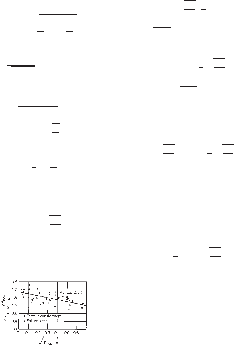
In addition, results of tests previously conducted by
Sechler and Winter indicate that the term C used in Eq.
(3.29) depends primarily on the nondimensional parameter
Figure 3.16 Experimental determination of effective width.
3.13
E
f
max
t
w
(3.30)
It has been found that a straight-line relationship exists
between
√
E/f
max
(t/w)andthetermC, as shown in
Fig. 3.16. The following equation for the term C has
been developed by Winter on the basis of his experimental
investigation
3.13,3.14
:
C = 1.9
1 − 0.475
t
w
E
f
max
(3.31)
It should be noted that the straight line in Fig. 3.16 starts
at a value of 1.9 for
√
E/f
max
(t/w) = 0, which represents
the case of an extremely large w/t ratio with relatively
high stress. For this particular case, the experimental deter-
minations are in substantial agreement with von Karman’s
original formula [Eq. (3.25)].
Consequently, in 1946 Winter presented the following
modified formula for computing the effective width b for
plates simply supported along both longitudinal edges:
b = 1.9t
E
f
max
1 − 0.475
t
w
E
f
max
(3.32)
It should be noted from Eq. (3.32) that the effective width
depends not only on the edge stress f
max
but also on the
w/t ratio.
Equation (3.32) may be written in terms of the ratio of
f
cr
/f
max
as
b
w
=
f
cr
f
max
1 − 0.25
f
cr
f
max
(3.33)
From the above equation it can be shown that a
compressed plate is fully effective, b = w, when the ratio
of w/t is less than
w
t
lim
= 0.95
E
f
max
(3.34)
and that the first wave occurs at a stress equal to f
cr
/4.
In summary, it may be considered that Eqs. (3.32) and
(3.33) are generalizations of Eqs. (3.25) and (3.28) in two
respects: (1) by introducing f
max
for F
y
, the equations can
be applied to service loads as well as to failure loads, and
(2) by introducing empirical correction factors, the cumula-
tive effects of various imperfections, including initial devi-
ations from planeness, are accounted for.
During the period from 1946 to 1968, the AISI design
provision for the determination of the effective design
width was based on Eq. (3.32). A longtime accumulated
experience has indicated that a more realistic equation, as
shown in Eq. (3.35), may be used in the determination of
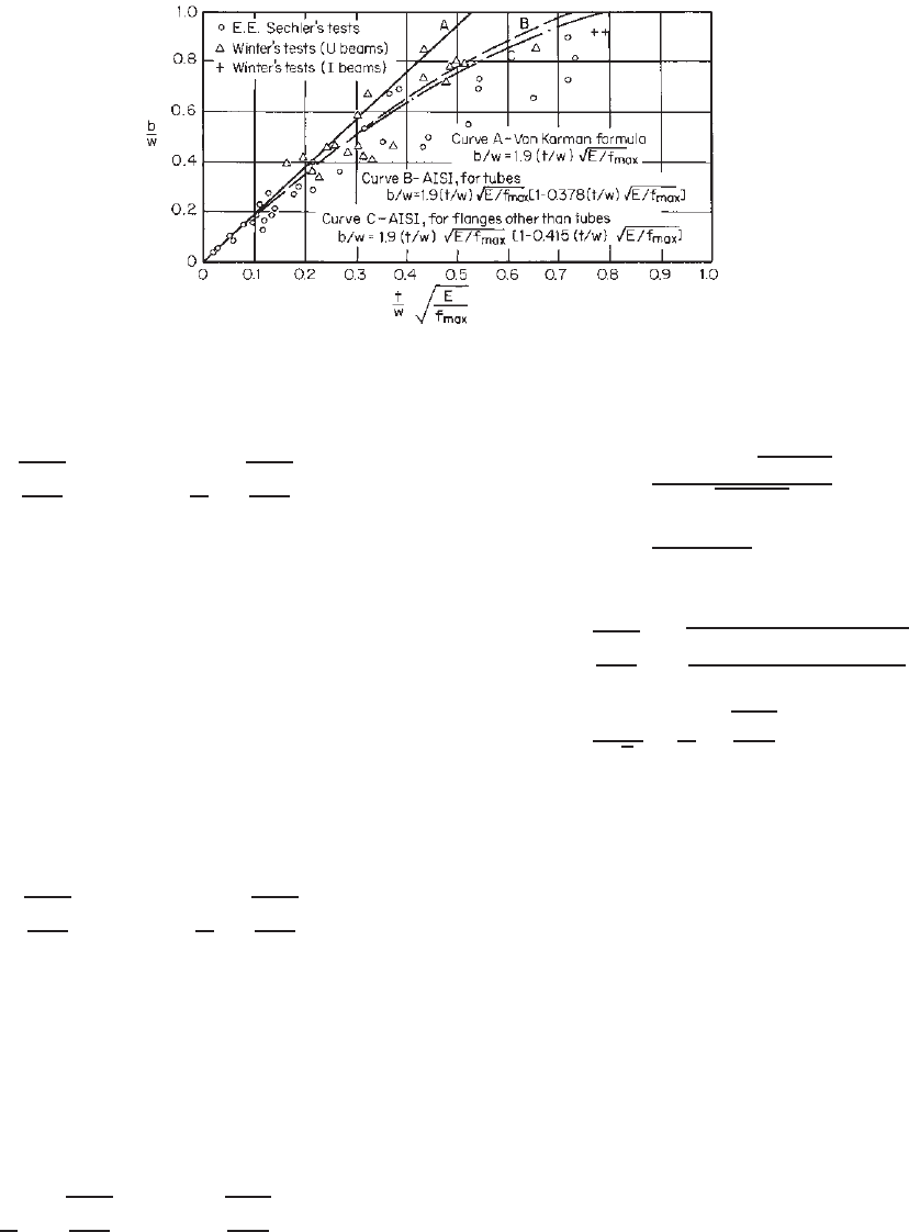
64 3 STRENGTH OF THIN ELEMENTS AND DESIGN CRITERIA
Figure 3.17 Correlation between test data on stiffened compression elements and design
criteria.
3.15
the effective width b
1.161
:
b = 1.9t
E
f
max
1 − 0.415
t
w
E
f
max
(3.35)
Figure 3.17 illustrates the correlation between Eq. (3.35)
and the results of tests conducted by Sechler and Winter.
It should be noted that Sechler’s tests were carried out on
disjointed single sheets, not on structural shapes. Hence the
imperfect edge conditions account for many low values in
his tests.
In view of the fact that Eq. (3.35) correlates well
with the s tiffened compression elements with little or no
rotational restraints along both longitudinal edges (i.e.,
k = 4), this equation can be generalized as shown below
for determining the effective width of stiffened elements
having different rotational edge restraints:
b = 0.95t
kE
f
max
1 − 0.208
t
w
kE
f
max
(3.36)
where k is the local buckling coefficient. The above
equation has been used in the Canadian standard.
1.177
In Ref. 3.16, Johnson pointed out that Eq. (3.36) can be
modified for the effects of inelastic buckling by replacing
E by ηE, where η is a plasticity reduction factor.
It should be noted that Eq. (3.35) may be rewritten in
terms of the f
cr
/f
max
ratio as follows:
b
w
=
f
cr
f
max
1 − 0.22
f
cr
f
max
(3.37)
Therefore, the effective width b can be determined as
b = ρw (3.38)
where the reduction factor ρ is given as
ρ =
1 − 0.22/
√
f
max
/f
cr
√
f
max
/f
cr
=
1 − 0.22/λ
λ
≤ 1 (3.39)
In Eq. (3.39), λ is a slenderness factor determined as
λ =
f
max
f
cr
=
f
max
[12(1 − μ
2
)(w/t)
2
]
kπ
2
E
=
1.052
√
k
w
t
f
max
E
(3.40)
in which k, w/t, f
max
,andE were previously defined. The
value of μ was taken as 0.3.
Figure 3.18 shows the relationship between ρ and λ.It
can be seen that, when λ ≤ 0.673, ρ = 1.0.
Based on Eqs. (3.38)–(3.40), the 1986 edition of the
AISI Specification adopted the nondimensional format in
Section B2.1 for determining the effective design width b
for uniformly compressed stiffened elements.
3.17,3.18
The
same design equations were used in the 1996 edition of the
AISI Specification and are retained in Section B2.1 of the
North A merican specification with minor editorial changes
as follows:
(a) Strength Determination
b =
w for λ ≤ 0.673 (3.41)
ρw for λ>0.673 (3.42)
where b = effective design width of uniformly
compressed element for strength determination
w = flat width of compression element
ρ = reduction factor determined from Eq. (3.39):