Еврокод 3. Проектирование стальных конструкций. Часть 4-1. Бункеры
Подождите немного. Документ загружается.


(2) For 'product type' silos (factory production), which are subject to full scale testing, 'deemed-to-
satisfy' criteria may be adopted for design purposes.
2.9 Action effects for limit state verifications
2.9.1 General
(1)P The general requirements set out in section 9 of EN 1990 shall be satisfied.
2.9.2 Partial factors for ultimate limit states
2.9.2.1 Partial factors for actions on silos
(1)P For persistent, transient and accidental design situations, the partial factors
γ
F
shall be taken
from EN 1990 and EN 1991-4.
(2) Partial factors for ‘product type’ silos (factory production) may be specified by the appropriate
authorities.
NOTE: When applied to ‘product type’ silos, the factors in (1) are for guidance purposes only. They
are provided to show the likely levels needed to achieve consistent reliability with other designs.
2.9.2.2 Partial factors for resistances
(1) Where structural properties are determined by testing, the requirements and procedures of EN
1990 should be adopted.
(2) Fatigue verifications should satisfy section 9 of EN 1993-1-6.
(3)P The partial factors
γ
Mi
for different limit states shall be taken from table 2.2.
Table 2.2: Partial factors for resistance
Resistance to failure mode Relevant
γ
Resistance of welded or bolted shell wall to
plastic limit state
γ
M0
Resistance of shell wall to stability
γ
M1
Resistance of welded or bolted shell wall to
rupture
γ
M2
Resistance of shell wall to cyclic plasticity
γ
M4
Resistance of connections
γ
M5
Resistance of shell wall to fatigue
γ
M6
NOTE: Partial factors
γ
Mi
for silos may be defined in the National Annex. For values of
γ
M5
, further
information may be found in EN 1993-1-8. For values of
γ
M6
, further information may be found in EN
1993-1-9. The following numerical values are recommended for silos:
γ
M0
= 1,00
γ
M1
= 1,10
γ
M2
= 1,25
γ
M4
= 1,00
γ
M5
= 1,25
γ
M6
= 1,10
For further differentiation, see 2.2(1) and 2.2(3)
EN 1993-4-1:2007 (Е)
16
2.9.3 Serviceability limit states
(1) Where simplified compliance rules are given in the relevant provisions dealing with
serviceability limit states, detailed calculations using combinations of actions need not be carried out.
2.10 Durability
(1) The general requirements set out in 2.6 of EN 1990 should be followed.
2.11 Fire resistance
(1) The provisions set out in EN 1993-1-2 for fire resistance should be met.
EN 1993-4-1:2007 (Е)
17
3 Properties of materials
3.1 General
(1) All steels used for silos should be suitable for welding to permit later modifications when
necessary.
(2) All steels used for silos of circular planform should be suitable for cold forming into curved
sheets or curved members.
(3) The material properties given in this section, see Table 3.1 in EN 1993-1-1 and Table 3.1b in
EN 1993-1-3, should be treated as nominal values to be adopted as characteristic values in design
calculations.
(4) Other material properties are given in the relevant Reference Standards defined in EN 1993-1-1.
(5) Where the silo may be filled with hot solids, the values of the material properties should be
appropriately reduced to values corresponding to the maximum temperatures to be encountered.
(6) Where the temperature exceeds 100°C, the material properties should be obtained from EN
13084-7.
3.2 Structural steels
(1) The methods for design by calculation given in this Part 4.1 of EN 1993 may be used for
structural steels as defined in EN 1993-1-1, which conform with the European Standards and
International Standards listed in table 3.1.
(2) The mechanical properties of structural steels, according to EN 10025 or EN 10149 should be
obtained from EN 1993-1-1, EN 1993-1-3 and EN 1993-1-4.
(3) Corrosion and abrasion allowances are given in section 4 of this Part 4.1.
(4) It should be assumed that the properties of steel in tension are the same as those in compression.
(5) For the steels covered by this Part 4.1 of EN 1993, the design value of the modulus of elasticity
should be taken as E = 210 000 MPa and Poisson’s ratio as
ν
= 0,3.
3.3 Stainless steels
(1) The mechanical properties of stainless steels should be obtained from EN 1993-1-4.
(2) Guidance for the selection of stainless steels in view of corrosion and abrasion actions of stored
solids may be obtained from appropriate sources.
(3) Where the design involves a buckling calculation, appropriate reduced properties should be
used (see EN 1993-1-6).
3.4 Special alloy steels
(1) For non-standardised alloy steels, appropriate values of relevant mechanical properties should
be defined.
NOTE: The National Annex may give information on appropriate values.
EN 1993-4-1:2007 (Е)
18
(2) Guidance for the selection of non-standardised alloy steels with respect to the corrosion and
abrasion actions of stored solids should be obtained from appropriate sources.
(3) Where the design involves a buckling calculation, appropriate reduced properties should be
used (see EN 1993-1-6).
3.5 Toughness requirements
(1) The toughness requirements for the steels should be determined according to EN 1993-1-10.
EN 1993-4-1:2007 (Е)
19
4 Basis for structural analysis
4.1 Ultimate limit states
4.1.1 Basis
(1) Steel structures and components should be so proportioned that the basic design requirements
given in section 2 are satisfied.
4.1.2 Required checks
(1)P For every relevant limit state, the design shall satisfy the condition:
S
d
< R
d
... (4.1)
where S and R represent any appropriate parameter.
4.1.3 Fatigue and cyclic plasticity - low cycle fatigue
(1) Parts of the structure subject to severe local bending should be checked against the fatigue and
cyclic plasticity limit states using the procedures of EN 1993-1-6 and EN 1993-1-7 as appropriate.
(2) Silos in Consequence Class 1 need not be checked for fatigue or cyclic plasticity.
4.1.4 Allowance for corrosion and abrasion
(1) The effects of abrasion of the stored solid on the walls of the container over the life of the
structure should be included in determining the effective thickness of the wall for analysis.
(2) Where no specific information is available, the wall should be assumed to lose an amount ∆t
a
of
its thickness due to abrasion at all points on contact with moving solid.
NOTE: The National Annex may choose the value of ∆t
a
. The value ∆t
a
= 2mm is recommended.
(3) The effects of corrosion of the wall in contact with the stored solid over the life of the structure
should be included in determining the effective thickness of the wall for analysis.
(4) Specific values for corrosion and abrasion losses, appropriate to the intended use, should be
agreed between the designer, the client and the relevant authority, taking account of the intended use
and the nature of the solids to be stored.
NOTE 1: The National Annex may choose appropriate values for corrosion and abrasion losses for
particular solids in frictional contact with defined silo wall materials, recognising the mode of solids
flow defined in EN 1991-4.
NOTE 2: To ensure that the design assumptions are met in service, appropriate inspection measures
have to be instituted.
4.1.5 Allowance for temperature effects
(1) Where hot solids are stored in the silo, the effects of differential temperature between parts of
the structure in contact with hot material and those that have cooled should be included in determining
the stress distribution in the wall.
EN 1993-4-1:2007 (Е)
20

4.2 Analysis of the structure of a shell silo
4.2.1 Modelling of the structural shell
(1) The modelling of the structural shell should follow the requirements of EN 1993-1-6. They
may be deemed to be satisfied by the following provisions.
(2) The modelling of the structural shell should include all stiffeners, large openings, and
attachments.
(3) The design should ensure that the assumed boundary conditions are satisfied.
4.2.2 Methods of analysis
4.2.2.1 General
(1) The analysis of the silo shell should be carried out according to the requirements of EN 1993-1-
6.
(2) A higher class of analysis may always be used than that defined for the Consequence Class.
4.2.2.2 Consequence Class 3
(1) For silos in Consequence Class 3 (see 2.3), the internal forces and moments should be
determined using a validated numerical analysis (finite element shell analysis) (as defined in EN
1993-1-6). Plastic collapse strengths under primary stress states may be used in relation to the plastic
limit state as defined in EN 1993-1-6.
4.2.2.3 Consequence Class 2
(1) For silos in Consequence Class 2 under conditions of axisymmetric actions and support, one of
two alternative analyses may be used:
a) Membrane theory may be used to determine the primary stresses. Bending theory elastic
expressions may be used to describe all local bending effects.
b) A validated numerical analysis may be used (e.g. finite element shell analysis) (as
defined in EN 1993-1-6).
(2) Where the design loading from stored solids cannot be treated as axisymmetric, a validated
numerical analysis should be used.
(3) Notwithstanding paragraph (2), where the loading varies smoothly around the shell causing
global bending only (i.e. in the form of harmonic 1), membrane theory may be used to determine the
primary stresses.
(4) For analyses of actions due to wind loading and/or foundation settlement and/or smoothly
varying patch loads (see EN 1991-4 for thin walled silos), semi-membrane theory or membrane theory
may be used.
(5) Where membrane theory is used to find the primary stresses in the shell:
a) Discrete rings attached to an isotropic cylindrical silo shell under internal pressure may
be deemed to have an effective area which includes a length of shell above and below the
ring of 0.78
rt except where the ring is at a transition junction.
b) The effect of local bending stresses at discontinuities in the shell surface and supports
should be evaluated separately.
EN 1993-4-1:2007 (Е)
21

(6) Where an isotropic shell wall is discretely stiffened by vertical stiffeners, the stresses in the
stiffeners and the shell wall may be calculated by treating the stiffeners as smeared on the shell wall,
provided the spacing of the stiffeners is no wider than n
vs
rt.
NOTE: The National Annex may choose the value of n
vs
. The value n
vs
= 5 is recommended.
(7) Where smeared stiffeners are used, the stress in the stiffener should be determined making
proper allowance for compatibility between the stiffener and the wall and including the effect of the
wall membrane stress in the orthogonal direction.
(8) Where a ring girder is used above discrete supports, membrane theory may be used to determine
the primary stresses, but the requirements of 5.4 and 8.1.4 concerning the evaluation of additional
non-axisymmetric primary stresses should be followed.
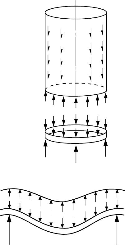
(9) Where a ring girder is used above discrete supports, compatibility of the deformations between
the ring and adjacent shell segments should be considered, see Figure 4.1. Particular attention should
be paid to compatibility of the axial deformations, as the induced stresses penetrate far up the shell.
Where such a ring girder is used, the eccentricity of the ring girder centroid and shear centre relative
to the shell wall and the support centreline should be considered, see 8.1.4 and 8.2.3.
EN 1993-4-1:2007 (Е)
22
C
Cyl
i
indri
c
cal
shell
Ax
i
isymm
e
et
r
r
i
ic
w
w
a
a
l
l
l
l
l
l
o
o
a
a
d
d
i
i
n
n
g
g
a
an
d
d
bot
t
tom
p
p
r
r
e
e
s
s
s
s
u
u
r
r
e
e
s
s
Uni
f
f
o
o
r
rm
s
s
u
upport
to
c
cylin
d
d
e
er
from
r
ri
n
ng
g
girder
Rin
g
g
g
i
ir
d
der
(
(
v
v
a
a
r
r
i
i
o
o
u
u
s
s
c
cross
-
-sec
t
tion
g
g
e
e
o
o
m
m
e
e
t
t
r
r
i
i
e
e
s
s
)
)
Discrete
l
o
ocal
suppo
r
rt
s
s
U
U
n
niform
l
o
oa
d
d
i
ing
of
r
r
i
i
n
n
g
g
g
g
i
i
r
r
d
d
e
e
r
r
b
b
y
y
c
c
y
y
l
l
i
i
n
n
d
d
e
e
r
r
a) Traditional design model for column-supported silos
S
S
h
h
e
e
l
l
l
l
w
w
a
a
l
l
l
l
D
D
i
i
s
s
c
c
r
r
e
e
t
t
e
e
s
u
u
p
ppor
t
t
Di
s
s
c
cre
t
te
s
s
u
u
p
p
p
p
o
o
r
r
t
t
I
I
n
n
-
-
p
p
l
l
a
a
n
n
e
e
v
v
e
e
r
r
t
t
i
i
c
c
a
a
l
l
de
f
f
l
le
c
ct
i
ions
R
i
ing
gi
r
r
d
d
e
er
d
d
e
efl
e
ec
t
te
d
d
sh
a
ape
b) Deformation requirement on cylinder imposed by compatibility with beam
de
formation
Figure 4.1: Axial deformation compatibility between ring girder and shell
(10) Where the silo is subject to any form of unsymmetrical bulk solids loading (patch loads,
eccentric discharge, unsymmetrical filling etc.), the structural model should be designed to capture the
membrane shear transmission within the silo wall and between the wall and rings.
NOTE: The shear transmission between parts of the wall and rings has special importance in
construction using bolts or other discrete connectors (e.g. between the wall and hopper, between
different strakes of the barrel).
(11) Where a ring girder is used to redistribute silo wall forces into discrete supports, and where
bolts or discrete connectors are used to join the structural elements, the shear transmission between
the parts of the ring due to shell bending and ring girder bending phenomena should be determined.
(12) Except where a rational analysis is used and there is clear evidence that the solid against the
wall is not in motion during discharge, the stiffness of the bulk solid in resisting wall deformations or
in increasing the buckling resistance of the structure should not be considered.
EN 1993-4-1:2007 (Е)
23
4.2.2.4 Consequence Class 1
(1) For silos in Consequence Class 1, membrane theory may be used to determine the primary
stresses, with factors and simplified expressions to describe local bending effects and unsymmetrical
actions.
4.2.3 Geometric imperfections
(1) Geometric imperfections in the shell should satisfy the limitations defined in EN 1993-1-6.
(2) For silos in Consequence Classes 2 and 3, the geometric imperfections should be measured
following construction to ensure that the assumed fabrication tolerance quality has been achieved.
(3) Geometric imperfections in the shell need not be explicitly included in determining the internal
forces and moments, except where a GNIA or GMNIA analysis is used, as defined in EN 1993-1-6.
4.3 Analysis of the box structure of a rectangular silo
4.3.1 Modelling of the structural box
(1) The modelling of the structural box should follow the requirements of EN 1993-1-7, but they
may be deemed to be satisfied by the following provisions.
(2) The modelling of the structural box should include all stiffeners, large openings, and
attachments.
(3) The design should ensure that the assumed boundary conditions are satisfied.
(4) The joints between segments of the box should satisfy the modelling assumptions for strength
and stiffness.
(5) Each panel of the box may be treated as an individual plate segment provided that both:
a) the forces and moments introduced into each panel by its neighbours are included;
b) the flexural stiffness of adjacent panels is included.
(6) Where an isotropic plate wall panel is discretely stiffened with horizontal stiffeners, the stresses
in the stiffeners and the box wall may be calculated by treating the stiffeners as smeared on the wall to
produce an orthotropic plate, provided that the spacing of the stiffeners is no wider than n
s
t.
NOTE: The National Annex may choose the value of n
s
. The value n
s
= 40 is recommended.
(7) Where smeared stiffeners are used, the stress in the stiffener should be determined making
proper allowance for the eccentricity of the stiffener from the wall plate, and for the wall stress in the
direction orthogonal to the axis of the stiffener.
(8) The effective width of plate on each side of a stiffener should be taken as not greater than n
ew
t,
where t is the local plate thickness.
NOTE: The National Annex may choose the value of n
ew
. The value n
ew
= 16 is recommended.
4.3.2 Geometric imperfections
(1) Geometric imperfections in the box should satisfy the limitations defined in EN 1993-1-7.
EN 1993-4-1:2007 (Е)
24
(2) Geometric imperfections in the box need not be explicitly included in determining the internal
forces and moments.
4.3.3 Methods of analysis
(1) The internal forces in the plate segments of the box wall may be determined using either:
a) static equilibrium for membrane forces and beam theory for bending;
b) an analysis based on linear plate bending and stretching theory;
c) an analysis based on nonlinear plate bending and stretching theory.
(2) For silos in Consequence Class 1, method (a) in (1) may be used.
(3) Where the design loading condition is symmetric relative to each plate segment and the silo is
in Consequence Class 2, method (a) in (1) may be used.
(4) Where the design loading condition is not symmetric and the silo is in Consequence Class 2,
either method (b) or method (c) in (1) should be used.
(5) For silos in Consequence Class 3 (see 2.3), the internal forces and moments should be
determined using either method (b) or method (c) in (1) (as defined in EN 1993-1-7).
4.4 Equivalent orthotropic properties of corrugated sheeting
(1) Where corrugated sheeting is used as part of the silo structure, the analysis may be carried out
treating the sheeting as an equivalent uniform orthotropic wall.
(2) The following properties may be used in a stress analysis and in a buckling analysis of the
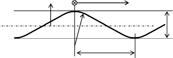
structure, provided that the corrugation profile has either an arc-and-tangent or a sinusoidal shape.
Where other corrugation profiles are used, the corresponding properties should be calculated from
first principles.
l
/ 2
d
x
R
φ
effective middle surface
z
y
Figure 4.2: Corrugation profile and geometric parameters
(3) The properties of the corrugated sheeting should be defined in terms of an x, y coordinate
system in which the y axis runs parallel to the corrugations (straight lines on the surface) whilst x
runs normal to the corrugations (troughs and peaks). The corrugation should be defined in terms of
the following parameters, irrespective of the actual corrugation profile, see figure 4.2:
where:
d is the crest to crest dimension;
l
is the wavelength of the corrugation;
R
φ
is
the local radius at the crest or trough.
EN 1993-4-1:2007 (Е)
25