Simmons C.H., Dennis E.M. Manual of Engineering Drawing
Подождите немного. Документ загружается.


60 Manual of Engineering Drawing
provides an inward or outward force to locate a
component within a bore or housing.
9 Clearance hole—A term used in an assembly to
describe a particular hole which is just a little
larger and will clear the bolt or stud which passes
through.
10 Counterbore—A counterbored hole may be used
to house a nut or bolthead so that it does not
project above a surface. It is machined so that the
bottom surface of the larger hole is square to the
hole axis.
11 Countersink—A hole which is recessed conically
to accommodate the head of a rivet or screw so
that the head will lie at the same level as the
surrounding surface.
12 Section plane or cutting plane—These are alter-
native terms used to define the positions of planes
from which sectional elevations and plans are
projected.
13 Dimension line—This is a narrow continuous line
which is placed outside the outline of the object,
if possible. The arrowheads touch the projection
lines. The dimension does not touch the line but
is placed centrally above it.
14 Enlarged view—Where detail is very small or
insufficient space exists for dimensions or notes
then a partial view may be drawn with an increased
size scale.
15 Round—This term is often used to describe an
external radius.
16 Fillet—This is the term given to the radii on internal
corners. Often found on castings, where its function
is to prevent the formation of stress cracks, which
can originate from sharp corners. Where three
surfaces meet on a casting the fillet radii will be
spherical.
17 Flange—This is a term to describe a projecting
rim or an edge which is used for stiffening or for
18
39
6
11 9
10
28 38
37
(168)
23
5
3
26
25
24
32
8
40 16 30 20 17
15 19
22 14
36
13
13
10
Enlarged view
scale 2:1
1.8
0.8
0.6
1
212
X
45°
70 PCD
4
27
X
4 Bosses equi-spaced
29
31
35
7
21
34
33
0.2 :1
Fig. 7.15
Drawing layouts and simplified methods 61
fixing. The example here is drilled for countersunk
screws.
18 Hatching—Note that cross hatching of the
component at the section plane is performed with
narrow continuous lines at 45°. Spacing between
the hatching lines varies with the size of the
component but should not be less than 4 mm.
19 Hidden detail—Indicated by a narrow dashed line.
Dashes of 3 mm and spaces of 2 mm are of
reasonable proportion.
20 Knurl—A surface finish with a square or diamond
pattern. Can be used in a decorative manner or to
improve grip.
21 Leader line—Leaders are used to indicate where
dimensions or notes apply and are drawn as narrow
continuous lines terminating in arrowheads or dots.
An arrowhead should always terminate on a line;
dots should be within the outline of the object.
22 Local section—A local section may be drawn if a
complete section or a half section is inconvenient.
The local break around the section is a continuous
narrow irregular line.
23 Machining centre—An accurately drilled hole with
a good finish at each end of the component which
enables the work to be located during a machining
operation on a lathe.
24 Machining symbol—If it is desired to indicate that
a particular surface is to be machined, without
further defining the actual machining process or
the surface finish, a symbol is added normal to
the line representing the surface. The included
angle of the symbol is approximately 60°. A general
note may be added to a drawing where all surfaces
are to be machined as follows:
25 Surface finish—If a surface is to be machined
and a particular quality surface texture is desired
then a standard machining symbol is added to the
drawing with a number which gives the maximum
permissible roughness expressed numerically in
micrometres.
26 Surface finish—If maximum and minimum degrees
of roughness are required then both figures are
added to the machining symbol.
27 Pitch circle diameter—A circle which passes
through the centres of a series of holes. The circle
is drawn with a long dashed dotted narrow line.
28 Recess—A hollow feature which is used to reduce
the overall weight of the component. A recess can
also be used to receive a mating part.
29 Slot—An alternative term to a slit, groove, channel
or aperture.
30 Spigot—This is a circular projection which is
machined to provide an accurate location between
assembled components.
31 Splined shaft—A rotating member which can
transmit a torque to a mating component. The
mating component may move axially along the
splines which are similar in appearance to keyways
around the spindle surface.
32 Square—Diagonal lines are drawn to indicate the
flat surface of the square and differentiate between
a circular and a square section shaft. The same
convention is used to show spanner flats on a
shaft.
33 Taper—A term used in connection with a slope
or incline. Rate of taper can also define a conical
form.
34 Taper symbol—The taper symbol is shown here
in a rectangular box which also includes dimen-
sional information regarding the rate of taper on
the diameter.
35 External thread—An alternative term used for a
male thread. The illustration here shows the thread
convention.
36 Internal thread—An alternative term for a female
thread. The illustration here shows the convention
for a female tapped hole.
37 Undercut—A circular groove at the bottom of a
thread which permits assembly without interference
from a rounded corner. Note in the illustration
that a member can be screwed along the M20
thread right up to the tapered portion.
38 Woodruff key—A key shaped from a circular disc
which fits into a circular keyway in a tapered
shaft. The key can turn in the circular recess to
accommodate any taper in the mating hub.
39 Key—A small block of metal, square or rectangular
in cross section, which fits between a shaft and a
hub and prevents circumferential movement.
40 Keyway—A slot cut in a shaft or hub to accom-
modate a key.
Drawing scales
Small objects are sometimes drawn larger than actual
size, while large components and assemblies, of
necessity, are drawn to a reduced size. A drawing should
always state the scale used. The scale on a full-size
drawing will be quoted as ‘ORIGINAL SCALE 1:1’.
Drawings themselves should not be scaled when in
use for manufacturing purposes, and warnings against
the practice are often quoted on standard drawing sheets,
e.g. ‘DO NOT SCALE’ and ‘IF IN DOUBT, ASK’. A
drawing must be adequately dimensioned, or referenced
sufficiently so that all sizes required are obtainable.
The recommended multipliers for scale drawings
are 2, 5, and 10.
1:1 denotes a drawing drawn full-size.
2:1 denotes a drawing drawn twice full-size.
5:1 denotes a drawing drawn five times full size.
Other common scales are 10:1, 20:1, 50 :1, 100 :1,
200:1, 500:1, and 1000 :1.
It should be pointed out that a scale drawing can be
deceiving; a component drawn twice full-size will cover
four times the area of drawing paper as the same
component drawn full-size, and its actual size may be
difficult to visualize. To assist in appreciation, it is a
common practice to add a pictorial view drawn full-
size, provided that the drawing itself is intended to be

62 Manual of Engineering Drawing
reproduced to the same scale and not reproduced and
reduced by microfilming.
The recommended divisors for scale drawings are
also 2, 5, and 10.
1:1 denotes a drawing drawn full-size.
1:2 denotes a drawing drawn half full-size.
1:5 denotes a drawing drawn a fifth full-size.
Other common scales used are 1:10, 1:20, 1:50, 1:100,
1:200, 1:500, and 1:1000.
The draughtsman will select a suitable scale to use
on a standard drawing sheet and this will depend on
the size of the object to be drawn. Remember that the
drawing must clearly show necessary information and
detail. It may be beneficial to make a local enlargement
of a small area and an example is given in Fig. 7.15.
Scale used in geometric
construction
Division of lines
Figure 7.16 shows the method of dividing a given line
AB, 89 mm long, into a number of parts (say 7).
Draw line AC, and measure 7 equal divisions. Draw
line B7, and with the tee-square and set-square draw
lines parallel to line B7 through points 1 to 6, to give
the required divisions on AB.
1 Draw a line 160 mm long.
2 Divide the line into four equal parts.
3 Draw 10 vertical divisions as shown and to any
reasonable scale (say 5 mm) and add diagonals.
An example of reading the scale is given.
Plain scales
The method of drawing a plain scale is shown in Fig.
7.19. The example is for a plain scale of 30 mm to 500
mm to read by 125 mm to 2500.
B
C
A
1
2
3
4
5
6
7
Fig. 7.16
Figure 7.17 shows an alternative method.
1 Draw vertical lines from A and B.
2 Place the scale rule across the vertical lines so that
seven equal divisions are obtained and marked.
3 Draw vertical lines up from points 2 to 7 to intersect
AB.
Diagonal scales
Figure 7.18 shows the method of drawing a diagonal
scale of 40 mm to 1000 which can be read by 10 mm
to 4000. Diagonal scales are so called since diagonals
are drawn in the rectangular part at the left-hand end
of the scale. The diagonals produce a series of similar
triangles.
Scale rule
A
90°
B
1
2
3
4
5
6
7
8
Fig. 7.17
2770 mm
100
80
60
40
20
1000 500 0 1000 2000 3000
mm mm
Fig. 7.18 Diagonal scale where 40 mm represents 1000 mm
500 mm 0
125 mm
500 mm
1000
2000
1375 mm
Fig. 7.19 Plain scale where 30 mm represents 500 mm
1 Draw a line 150 mm long and divide it into 5 equal
parts.
2 Divide the first 30 mm length into four equal parts,
and note the zero position or, the solution.
An example of a typical reading is given.

Drawing layouts and simplified methods 63
This method of calibration is in common use in
industry, and scales can be obtained suitable for a variety
of scale ratios.
Abbreviations
In order to shorten drawing notes we often use
abbreviations, and the following list gives a selection
of commonly used terms in accordance with BS 8888.
Term Abbreviation or
symbol BS 8888
Across flats A/F
Assembly ASSY
Centres CRS
Centre line:
(a) on a view and across a centre line
C
L
(b) in a note CL
Centre of gravity CG
Chamfer or chamfered (in a note) CHAM
Cheese head CH HD
Countersunk/countersink CSK
Countersunk head CSK HD
Counterbore CBORE
Cylinder or cylindrical CYL
Diameter:
(a) In a note DIA
(b) Preceding a dimension Ø
Dimension DIM
Drawing DRG
Equally spaced EQUI SP
External EXT
Figure FIG
Full indicated movement FIM
Hexagon HEX
Hexagon head HEX HD
Insulated or insulation INSUL
Internal INT
Least material condition:
(a) In a note LMC
(b) Part of a geometrical tolerance L
Left hand LH
Long LG
Machine MC
Material MATL
Maximum MAX
Maximum material condition:
(a) In a note MMC
(b) Part of geometrical tolerance M
Minimum MIN
Not to scale (in a note and underlined) NTS
Number NO.
Pattern number PATT NO.
Pitch circle diameter PCD
Radius:
(a) In a note RAD
(b) Preceding a dimension R
Reference REF
Required REQD
Right hand RH
Round head RD HD
Screw or screwed SCR
Sheet (referring to a drawing sheet) SH
Sketch (prefix to a drawing number) SK
Specification SPEC
Spherical diameter (only preceding
a dimension) SØ
Spherical radius (only preceding
a dimension) SR
Spotface SFACE
Square:
(a) In a note SQ
(b) Preceding a dimension or
Standard STD
Taper (on diameter or width)
Thread THD
Thick THK
Tolerance TOL
Typical or typically TYP
Undercut UCUT
Volume VOL
Weight WT
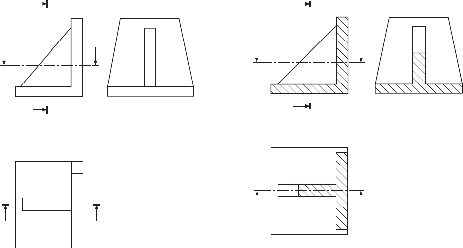
A section is used to show the detail of a component, or
an assembly, on a particular plane which is known as
the cutting plane. A simple bracket is shown in Fig.
8.1 and it is required to draw three sectional views.
Assume that you had a bracket and cut it with a hacksaw
along the line marked B–B. If you looked in the
direction of the arrows then the end view B–B in the
solution (Fig. 8.2), would face the viewer and the surface
indicated by the cross hatching would be the actual
metal which the saw had cut through. Alternatively
had we cut along the line C–C then the plan in the
solution would be the result. A rather special case
exists along the plane A–A where in fact the thin web
at this point has been sliced. Now if we were to cross
hatch all the surface we had cut through on this plane
we would give a false impression of solidity. To provide
a more realistic drawing the web is defined by a full
line and the base and perpendicular parts only have
been cross hatched. Note, that cross hatching is never
undertaken between dotted lines, hence the full line
between the web and the remainder of the detail.
However, the boundary at this point is theoretically a
dotted line since the casting is formed in one piece
and no join exists here. This standard drawing
convention is frequently tested on examination papers.
Cutting planes are indicated on the drawing by a
long chain line 0.35 mm thick and thickened at both
ends to 0.7 mm. The cutting plane is lettered and the
arrows indicate the direction of viewing. The sectional
view or plan must then be stated to be A–A, or other
letters appropriate to the cutting plane. The cross
hatching should always be at 45° to the centre lines,
with continuous lines 0.35 mm thick.
If the original drawing is to be microfilmed successive
lines should not be closer than 4 mm as hatching lines
tend to merge with much reduced scales. When hatching
very small areas the minimum distance between lines
should not be less than 1 mm.
In the case of very large areas, cross hatching may
be limited to a zone which follows the contour of the
hatched area. On some component detail drawings it
may be necessary to add dimensions to a sectional
drawing and the practice is to interrupt the cross hatching
so that the letters and numbers are clearly visible.
Chapter 8
Sections and sectional views
Fig. 8.1 Fig. 8.2
B
CC
B
A
A
B
CC
B
B–B
A–A
A
A
C–C
Sections and sectional views 65
If the interior of a component is of an intricate nature
or it contains several parts to form an assembly, then
the customary orthographic drawing would contain a
confusion of dotted lines, which, in addition to being
difficult to draw could also be terribly difficult to
understand. The reader of any engineering drawing
should be able to obtain only one positive interpretation
of the component, or the draughtsman has failed in his
duty. Sectional drawings are prepared which cut away
a portion of the component to reveal internal details
and certain standard conventions have been established
to cover this aspect of drawing practice.
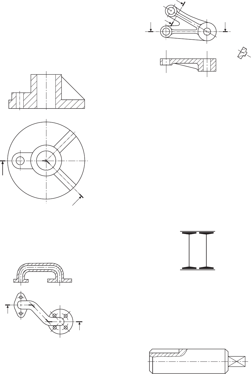
Figure 8.5 shows some advantages of drawing a
sectional view with a small cast component.
Note, that in Plan (A), the sectional plan gives clearly
the exact outline along the horizontal axis where the
casting has assumed to have been cut. This contrasts
with the confusion in Plan (B) which obviously results
from attempting to include all the detail by inserting
the appropriate dotted lines.
Where the location of a single cutting plane is
obvious, no indication of its position or identification
is required. Figure 8.6 gives a typical example.
Half sections
Symmetrical parts may be drawn half in section and
half in outside view. This type of drawing avoids the
necessity of introducing dotted lines for the holes and
the recess. Dimensioning to dotted lines is not a
recommended practice.
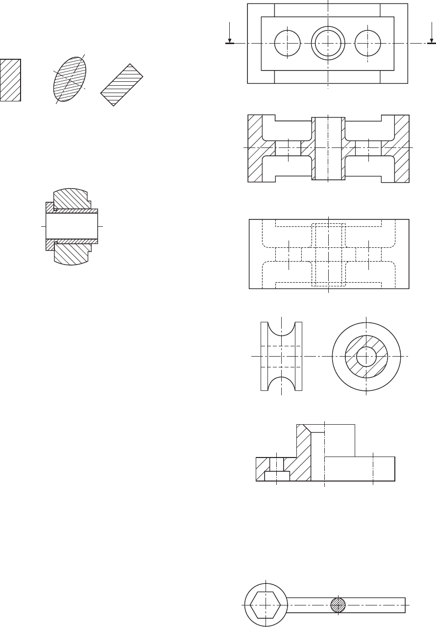
Revolved sections
A special spanner is illustrated in Fig. 8.8. A revolved
section is shown on the handle to indicate the shape of
Figure 8.3 shows three typical cases of cross hatching.
Note that the hatching lines are equally spaced and
drawn at an angle of 45° to the principal centre line in
each example.
Fig. 8.3
A bush is shown in Fig. 8.4 in a housing. There are
two adjacent parts and each is cross hatched in opposite
directions. It is customary to reduce the pitch between
hatching lines for the smaller part.
Fig. 8.4
A
A
Plan A
A–A
Plan B
Fig. 8.5
Fig. 8.6
Fig. 8.7
Fig. 8.8
66 Manual of Engineering Drawing
Figure 8.10 shows a sectioned elevation from a plan
where the section line is taken along three neighbouring
planes which are not at right angles to one another.
The section line follows the section planes in order,
and is thickened at each change of direction.
since the removed section only indicates the true shape
of the casting at the point where the section has been
taken. B–B gives the section along the horizontal centre
line through the thin web.
Sections through thin
material
Many products are manufactured from very thin
materials which would be virtually impossible to cross
hatch in a sectional view and in these cases it is usual
to make them entirely black. Where however two or
more thin sections are adjacent to each other, a gap is
left so that the profile of the separate components is
clearly defined. A compound stanchion used in structural
steelwork and drawn to reduced scale is shown in Fig.
8.12. The same situation applies with sections through
sheet-metal fabrications, gaskets, seals and packings.
Fig. 8.9
the cross section at that point. This is a convenient
convention to use on single view drawings because
the shape could not be confirmed without projecting a
second view or an added note.
A second type of revolved section in Fig. 8.9 shows
a case where it is required to indicate details on two
separate intersecting planes. The elevation in section
has been drawn assuming that the right hand plane has
been revolved to the horizontal position. Note that the
thin web is not cross hatched.
A–A
A
A
X–X
x
x
Fig. 8.10
Removed sections
A removed section is shown in Fig. 8.11. Note that no
additional background information has been included,
A
A
B
B
B–B
A–A
Fig. 8.11
Fig. 8.12
Local sections
It is not always necessary to draw a complete section
through a component if a small amount of detail only
needs to be illustrated. A typical example is shown in
Fig. 8.13 where a keyway is drawn in a section. The
irregular line defines the boundary of the section. It is
not required to add a section plane to this type of view.
Fig. 8.13
Sections and sectional views 67
Components not drawn in
section
It is the custom not to section many recognizable
components in assembly drawings positioned along
the cutting plane; these include nuts, bolts, washers,
rivets, pins keys, balls, rollers, spokes of wheels and
similar symmetrical parts.
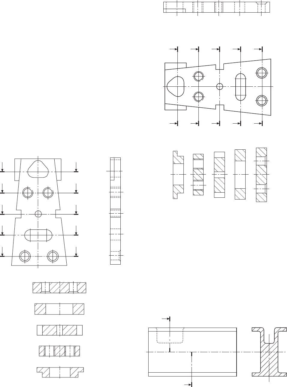
Successive sections
Figure 8.14 shows the front and end elevations of a
special purpose mounting plate where sectional plans
are given at different levels to illustrate the shapes of
the various cutouts and details. Now it will be noted
that the presentation of this problem takes considerable
vertical space since all of the plan views are in correct
projection. The current British Standard permits
successive sections to be drawn as shown in Fig. 8.14.
Note that where successive sections are drawn, each
view only gives the detail at that section plane and not
additional background information. Figure 8.15 gives
the details at each of the section planes in a much
closer and less remote arrangement.
Sections in two parallel
planes
Figure 8.16 shows a method of presenting two sections
from parallel planes along the same part.
E
D
C
B
A
E
D
C
B
A
A–A
B–B
C–C
D–D
E–E
Fig. 8.14
E
D
C
B
A
ED
C
B
A
E–E D–D C–C B–B
A–A
Fig. 8.15
A
A
A–A
Fig. 8.16
Students will often experience difficulty in handling
problems involving two and three dimensional geo-
metrical constructions. The examples in Chapters 9 to
13 are included in order to provide a background in
solving engineering problems connected with lines,
planes and space. The separate chapters are grouped
around applications having similar principles.
Copying a selection of these examples on the drawing
board or on CAD equipment will certainly enable the
reader to gain confidence. It will assist them to visualize
and position the lines in space which form each part of
a view, or the boundary, of a three dimensional object.
It is a necessary part of draughtsmanship to be able to
justify every line and dimension which appears on a
drawing correctly.
Many software programs will offer facilities to
perform a range of constructions, for example tangents,
ellipses and irregular curves. Use these features where
possible in the examples which follow.
Assume all basic dimensions where applicable.
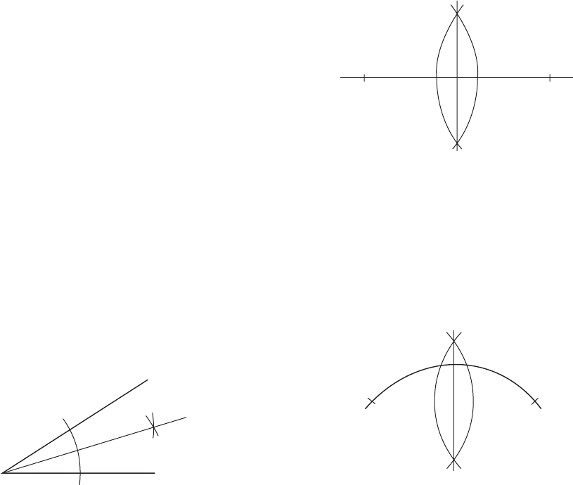
To bisect a given angle AOB (Fig. 9.1)
1 With centre O, draw an arc to cut OA at C and OB
at D.
2 With centres C and D, draw equal radii to intersect
at E.
2 Repeat with the same radius from B, the arcs
intersecting at C and D.
3 Join C to D and this line will be perpendicular to
and bisect AB.
Chapter 9
Geometrical constructions and
tangency
Fig. 9.1
O
C
D
A
E
B
3 Line OE bisects angle AOB.
To bisect a given straight line AB
(Fig. 9.2)
1 With centre A and radius greater than half AB,
describe an arc.
C
A
B
D
Fig. 9.2
To bisect a given arc AB (Fig. 9.3)
1 With centre A and radius greater than half AB,
describe an arc.
2 Repeat with the same radius from B, the arcs
intersecting at C and D.
3 Join C to D to bisect the arc AB.
C
A
B
D
Fig. 9.3
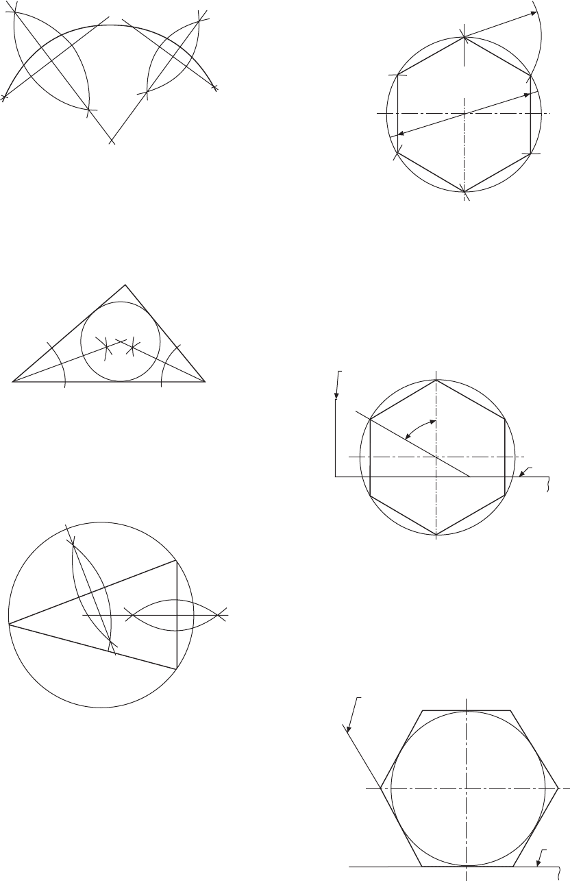
To find the centre of a given arc AB
(Fig. 9.4)
1 Draw two chords, AC and BD.
2 Bisect AC and BD as shown; the bisectors will
intersect at E.
3 The centre of the arc is point E.
Geometrical constructions and tangency 69
To inscribe a circle in a given triangle
ABC (Fig. 9.5)
1 Bisect any two of the angles as shown so that the
bisectors intersect at D.
2 The centre of the inscribed circle is point D.
Method B (Fig. 9.7(b))
1 Draw vertical and horizontal centre lines and a circle
with a diameter equal to the given distance.
2 With a 60° set-square, draw points on the
circumference 60° apart.
3 Connect these six points by straight lines to give
the required hexagon.
C
A
B
D
E
Fig. 9.4
A
B
D
C
Fig. 9.5
To circumscribe a circle around triangle
ABC (Fig. 9.6)
1 Bisect any two of the sides of the triangle as shown,
so that the bisectors intersect at D.
2 The centre of the circumscribing circle is point D.
B
D
A
C
Fig. 9.6
To draw a hexagon, given the distance
across the corners
Method A (Fig. 9.7(a))
1 Draw vertical and horizontal centre lines and a circle
with a diameter equal to the given distance.
2 Step off the radius around the circle to give six
equally spaced points, and join the points to give
the required hexagon.
Circle
radius
Diameter = distance
across corners
Fig. 9.7(a)
60° set-square
60°
Tee-square
Fig. 9.7(b)
To draw a hexagon, given the distance
across the flats (Fig. 9.8)
1 Draw vertical and horizontal centre lines and a circle
with a diameter equal to the given distance.
2 Use a 60° set-square and tee-square as shown, to
give the six sides.
60° set-square
Tee-square
Fig. 9.8