AckermannTh. (ed) Wind Power in Power Systems
Подождите немного. Документ загружается.


//INTEGRAS/KCG/P AGIN ATION/ WILEY /WPS /FINALS_1 4-12- 04/0470855088_ 26_CHA25 .3D – 561 – [555–586/32]
17.12.2004 10:50PM
Finally, we will describe the modelling of the turbulence. The turbulence component of
the wind speed is characterised by a power spectral density. Here, the following power
spectral density is used:
P
Dt
ðf Þ¼l
v
wa
ln
h
z
0
2
"#
1
1 þ 1:5
fl
v
wa
5/3
; ð25:4Þ
in which P
Dt
is the power de nsity of the turbulence for a certain frequency (W/Hz); f is
the frequency (Hz); h is the height at which the wind speed signal is of interest (m), which
normally equals the height of the wind turbine shaft; v
wa
is the mean wind speed (m/s); l
is the turbulence length scale (m), which equals 20 h if h is less than 30 m, and equals 600
if h is more than 30 m; and z
0
is the roughness length (m) . Through the parameter z
0
,we
take into account the dependence of the turbulence intensity on the landscape where the
wind turbine is located. The roughness length depends on the structure of the landscape
surrounding the wind turbine. Table 25.1 gives the values of z
0
for various landscape
types (Panofsky and Dutton, 1984; Simiu and Scanlan, 1986).
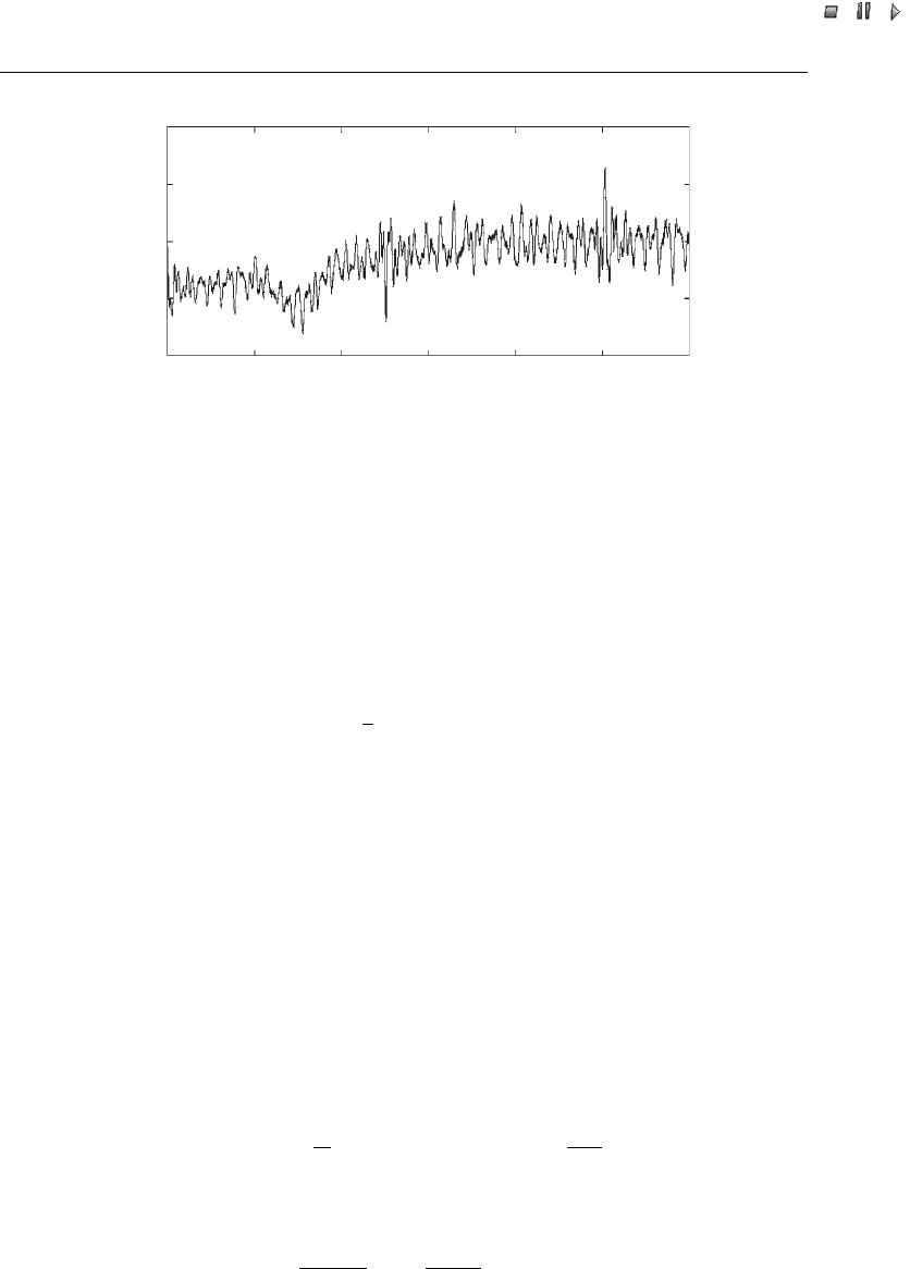
The fact that PSDSs are carried out in the time domain, whereas the turbulence of the
wind is described by a power spectral density given in the frequency domain, raises a
specific problem: the translation of a power spectral density into a time sequence of
values with the given power spectral density. To solve this problem, we use a method
that is described in Shinozuka and Jan (1972). This method works as follows. A power
spectral density can be used to derive information abou t the amplitude of a signal’s
component with a given frequency. Then, a large number of sines with a random initial
phase angle and an amplitude calculated from the power spectral density are added for
each time step. Thus we can generate a time domain signal with a power spectral density
that is a sampled equivalent of the original power spectral density. The smal ler the
frequency difference between the components, the better the power spectral density of
the artificially generated signal resembles the original power spectral density. The
required computation time will increase, though. For more information on the method
that we used for generating time domain signals with a given power spectral density, the
reader is referred to Shinozuka and Jan (1972). Figure 25.2 shows an example of a wind
speed sequence generated using this approach.
Table 25.1 Value of roughness length, z
0
, for various landscape types
Landscape type Range of z
0
(m)
Open sea or sand 0.0001–0.001
Snow surface 0.001–0.005
Mown grass or steppe 0.001–0.01
Long grass or rocky ground 0.04–0.1
Forests, cities or hilly areas 1–5
Sources: Panofsky and Dutton, 1984; Simiu and Scanlan, 1986.
Wind Power in Power Systems 561
//INTEGRAS/KCG/P AGIN ATION/ WILEY /WPS /FINALS_1 4-12- 04/0470855088_ 26_CHA25 .3D – 562 – [555–586/32]
17.12.2004 10:50PM
25.5.3 Rotor model
The following well-known algebraic equation gives the relation between wind speed and
mechanical power extracted from the wind (Heier, 1998; Patel, 2000):
P
wt
¼
2
A
wt
c
p
ð; Þ
3
w
; ð25:5Þ
where P
wt
is the power extracted from the wind in watts; is the air density (kg/m
3
); c
p
is
the performance coefficient or power coefficient; is the tip speed ratio v
t
/v
w
, the ratio
between blade tip speed, v
t
(m/s), and wind speed at hub height upstream of the rotor, v
w
(m/s); is the pitch angle (in degrees); and A
wt
is the area covered by the wind turbine
rotor (m
2
). Most constant-speed wind turbines are stall controlled. In that case, is left
out and c
p
is a function of only.
Manufacturer documentation shows that the power curves of individual wind tur-
bines are very similar. We therefore do not consider it necessary to use different
approximations for the c
p
() curve for different constant-speed wind turbines in PSDSs.
Instead, a general approximation can be used. We would like to stress that this does not
necessarily apply to other types of calculations, such as energy yield calculations for
financing purposes. Here, we use the following general equation to describe the rotor of
constant-speed and variable-speed wind turbines:
c
p
ð; Þ¼c
1
c
2
i
c
3
c
4
c
5
c
6
exp
c
7
i
; ð25:6Þ
where
1
þ c
8
c
9
3
þ 1
1
: ð25:7Þ
0102030405060
5
10
15
20
25
Time (s)
Wind speed (m/s)
Figure 25.2 Example of a simulated wind speed sequence, with the following input values:
average wind speed, v
wa
, 11.5 m/s; start time of wind speed ramp, T
sr
, 5 s; end time of wind speed
ramp, T
er
, 35 s; amplitude of wind speed ramp,
^
AA
r
, 4 m/s; start time of wind speed gust, T
sg
,5s;
end time of wind speed gust, T
eg
, 15 s; amplitude of wind speed gust,
^
AA
g
¼3 m/s; and roughness
length, z
0
, 0.01 m
562 Reduced-order Modelling of Wind Turbines
//INTEGRAS/KCG/P AGIN ATION/ WILEY /WPS /FINALS_1 4-12- 04/0470855088_ 26_CHA25 .3D – 563 – [555–586/32]
17.12.2004 10:50PM
The structure of this equation originates from Heier (1998). However, the values of the
constants c
1
to c
9
have been changed slightly in order to match the manufacturer data
better. To minimise the error between the curve in the manufacturer documentation and
the curve we obtained by using Equations (25.6) and (25.7), we applied multidimensional
optimisation. Table 25.2 includes both the original parameters and the parameters used
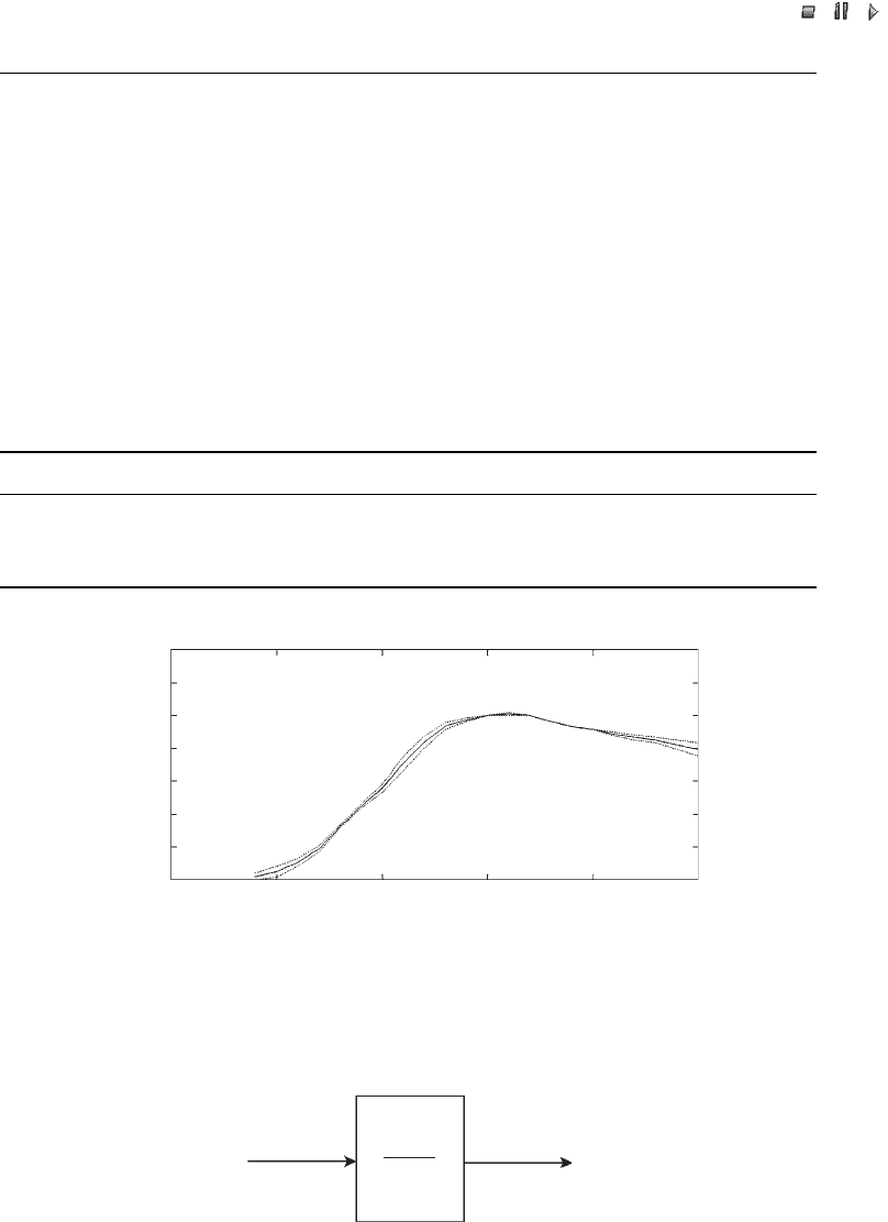
here. Figure 25.3 depicts the power curves of two commercial constant-speed wind
turbines, together with the generic numerical approximation from Table 25.2.
High-frequency wind speed variations are very local and therefore even out over the
rotor surface, particularly when wind turbines become larger. To approximate this
effect, a low-pass filter is included in the rotor model. Figure 25.4 illustrates the low-pass
Table 25.2 Approximation of power curves
c
1
c
2
c
3
c
4
c
5
c
6
c
7
c
8
c
9
Heier (1998) 0.5 116 0.4 0 — 5 21 0.08 0.035
Constant-speed wind turbine 0.44 125 0 0 0 6.94 16.5 0 0.002
Variable-speed wind turbine 0.73 151 0.58 0.002 2.14 13.2 18.4 0.02 0.003
0 5 10 15 20 25
0
0.2
0.4
0.6
0.8
1
1.2
1.4
Output Power (p.u.)
Wind speed (m/s)
Figure 25.3 Comparison of the numerical approximation of the power curve of a stall-controlled
wind turbine (solid curve) with the power curves of two commercial stall-controlled wind turbines
(dotted lines)
Wind
speed
(m/s)
Filtered
wind
speed
(m/s)
1
1
+
τs
Figure 25.4 Low-pass filter for representing the evening out of high-frequency wind speed
components over the rotor surface
Wind Power in Power Systems 563

//INTEGRAS/KCG/P AGIN ATION/ WILEY /WPS /FINALS_1 4-12- 04/0470855088_ 26_CHA25 .3D – 564 – [555–586/32]
17.12.2004 10:50PM
filter. The value of the time constant depends on the rotor diameter as well as on the
turbulence intensity of the wind and the average wind speed (Petru and Thiringer, 2000).
For the wind turbine analysed here, was set to 4.0 s.
Finally, we would like to include the tower shadow in the rotor model. This can be
done by adding a periodic pulsation to the mechanical power that is the output of the
rotor model, as calculated with Equation (25.5). The frequency of this pulsation depends
on the number of blades (normally three) and the rotational speed of the wind turbine
rotor. The amplitude of the pulsation is in the order of a few percent. The tower shadow
is particularly important in investigations concerning power quality an d the mutual
interaction between wind turbines that are situated close to each other, electrically.
25.5.4 Shaft model
It has been repeat edly argued in the literature that the incorporation of a shaft repre-
sentation in models of constant-speed wind turbines (Type A) is very important for a
correct representation of their behaviour during and after voltage drops and short
circuits (e.g . see Akhmatov, Knudsen and Nielsen, 2000). This is because of the fact
that the low-speed shaft of wind turbin es is relatively soft (Hinrichsen and Nolan, 1982).
The models presented here are to be used for PSDSs. These are, among others, used for
analysing a power system’s response to the mentioned disturbances. It is therefore
essential to incorporate a shaft representation into the constant-speed wind turbine
model. However, only the low-speed shaft is included. The gearbox and the high-speed
shaft are assumed to be infinitely stiff. The resonance frequencies associated with
gearboxes and high-speed shafts usually lie outside the frequency bandwidth that we
deal with in PSDSs (Akhmatov, Knudsen and Nielsen, 2000; Papathanassiou and
Papadopoulos, 1999). Therefore, we use a two-mass representation of the drive train.
The two-mass representation is described by the following equations:
d!
wr
dt
¼
T
wr
K
s
2H
wr
;
d!
m
dt
¼
K
s
T
e
2H
m
;
d
dt
¼ 2fð!
wr
!
m
Þ;
9
>
>
>
>
>
>
=
>
>
>
>
>
>
;
ð25:8Þ
in which f is the nominal grid frequency; T is the torque; is the angular displacement
between the two ends of the shaft; ! is frequency; H is the inertia constant; and K
s
is the
shaft stiffness. The subscripts wr, m and e stand for wind turbine rotor, generator
mechanical and generator electrical, respectively. All values are in per unit, apart from
K
s
, and f, which are in p.u./el. rad., degrees, and hertz, respectively.
The resonance frequency of the shaft’s torsional mode was experimentally determined
as 1.7 Hz (Pedersen et al ., 2000). When resonance frequency and the inertia constants of
the generator and the turbine rotor are known, K
s
can be calcul ated by using the general
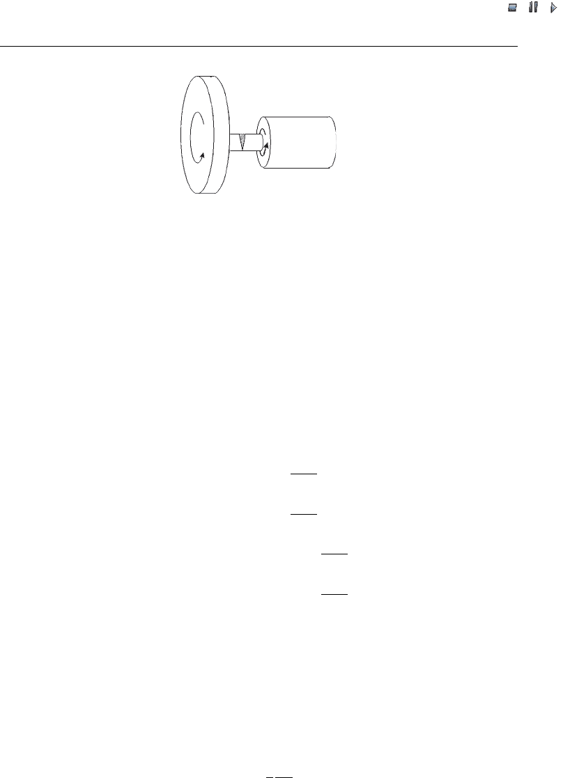
equation describing a two-mass system (Anderson, Agrawal and Van Ness, 1990). The
shaft is depicted schematically in Figure 25.5, which includes some of the quantities
from Equation (25.8).
564 Reduced-order Modelling of Wind Turbines
//INTEGRAS/KCG/P AGIN ATION/ WILEY /WPS /FINALS_1 4-12- 04/0470855088_ 26_CHA25 .3D – 565 – [555–586/32]
17.12.2004 10:50PM
25.5.5 Generator model
The voltage equations of a squirrel cage induction generator in the d – q (direct –
quadrative) reference frame, using the generator convention, can be found in the
literature (Kundur, 1994) and are as follows
u
ds
¼R
s
i
ds
!
s
qs
þ
d
ds
dt
;
u
qs
¼R
s
i
qs
þ !
s
ds
þ
d
qs
dt
;
u
dr
¼ 0 ¼R
r
i
dr
s!
s
qr
þ
d
dr
dt
;
u
qr
¼ 0 ¼R
r
i
qr
þ s!
s
dr
þ
d
qr
dt
;
9
>
>
>
>
>
>
>
>
>
>
>
>
=
>
>
>
>
>
>
>
>
>
>
>
>
;
ð25:9Þ
in which s is the slip, u is the voltage, i is the current, R is the resistance, and is the flux.
All quantities are in per unit. The subscripts d and q stand for direct and quadrature
component, respectively, and the subscripts r and s for rotor and stator, respectively.
The generator convention is used in this equation, which means that a current leaving
the machine is positive, whereas a current entering the machine is negative. The opposite
of the generator convention is the motor convention, where a current entering the
machine is positive whereas a current leaving the machine is negative.
The slip is defined as follows:
s ¼ 1
p
2
!
m
!
s
; ð25:10Þ
in which p is the number of poles. With respect to per unit (p.u.) quantities, it should
be noted at this point that the goal of using them is to make impedances independent
Shaft Generator
rotor
Wind
turbine
rotor
H
m
H
wr
ω
wr
γ
ω
m
Figure 25.5 Schematic representation of the shaft, including some of the quantities from Equ-
ation (25.8): H
wr
and H
m
¼inertia constant for the wind turbine rotor and generator rotor,
respectively; !
wr
and !
m
¼ angular frequency of wind turbinerotor and generator rotor,
respectively; ¼ angular displacement between shaft ends
Wind Power in Power Systems 565

//INTEGRAS/KCG/P AGIN ATION/ WILEY /WPS /FINALS_1 4-12- 04/0470855088_ 26_CHA25 .3D – 566 – [555–586/32]
17.12.2004 10:50PM
of voltage level and generat or rating by expressing them as a percentage of a
common base value. For an elaborate treatment of p.u. calculation and the correl-
ation between physical and p.u. values, see general textbooks on power systems, such
as Grainger and Stevenson (1994) . The flux linkages in Equation (25.9) can be
calculated by using the following equations, in which, again, the generator conven-
tion is used:
ds
¼ðL
s
þ L
m
Þi
ds
L
m
i
dr
;
qs
¼ðL
s
þ L
m
Þi
qs
L
m
i
qr
;
dr
¼ðL
r
þ L
m
Þi
dr
L
m
i
ds
;
qr
¼ðL
r
þ L
m
Þi
qr
L
m
i
qs
:
9
>
>
>
>
>
>
>
=
>
>
>
>
>
>
>
;
ð25:11Þ
In these equati ons, is flux linkage and L is the inductance. The indices m, r and stand
for mutual, rotor and leakage, respectively. By inserting Equations (25.11) in Equations
(25.9), while neglecting the stator transients, in agreement with the assumptions
discussed above, the voltage current relationships become:
u
ds
¼R
s
i
ds
þ !
s
½ðL
s
þ L
m
Þi
qs
þ L
m
i
qr
;
u
qs
¼R
s
i
qs
!
s
½ðL
s
þ L
m
Þi
ds
þ L
m
i
dr
;
u
dr
¼ 0 ¼R
r
i
dr
þ s!
s
½ðL
r
þ L
m
Þi
qr
þ L
m
i
qs
þ
d
dr
dt
;
u
qr
¼ 0 ¼R
r
i
qr
s!
s
½ðL
r
þ L
m
Þi
dr
þ L
m
i
ds
þ
d
qr
dt
:
9
>
>
>
>
>
>
>
>
>
>
>
=
>
>
>
>
>
>
>
>
>
>
>
;
ð25:12Þ
The electrical torque, T
e
, is given by:
T
e
¼
qr
i
dr
dr
i
qr
; ð25:13Þ
and the equation of the motion of the generator is:
d!
m
dt
¼
1
2H
m
ðT
m
T
e
Þ: ð25:14Þ
The equations for active power generated, P, and the reactive power consumed, Q , are:
P
s
¼ u
ds
i
ds
þ u
qs
i
qs
;
Q
s
¼ u
qs
i
ds
u
ds
i
qs
:
)
ð25:15Þ
Because only the stator winding is connected to the grid, generator and grid can
exchange active and reactive power only through the stator terminals. Therefore, the
rotor does not need to be taken into account. The values of the various parameters are
dependent on the generator rating and can be derived from tables and graphs (Heier,
1998). Table 25.3 includes the generator parameters used in this Chapter.
566 Reduced-order Modelling of Wind Turbines
//INTEGRAS/KCG/P AGIN ATION/ WILEY /WPS /FINALS_1 4-12- 04/0470855088_ 26_CHA25 .3D – 567 – [555–586/32]
17.12.2004 10:50PM
25.6 Model of a Wind Turbine with a Doubly fed Induction Generator
25.6.1 Model structure
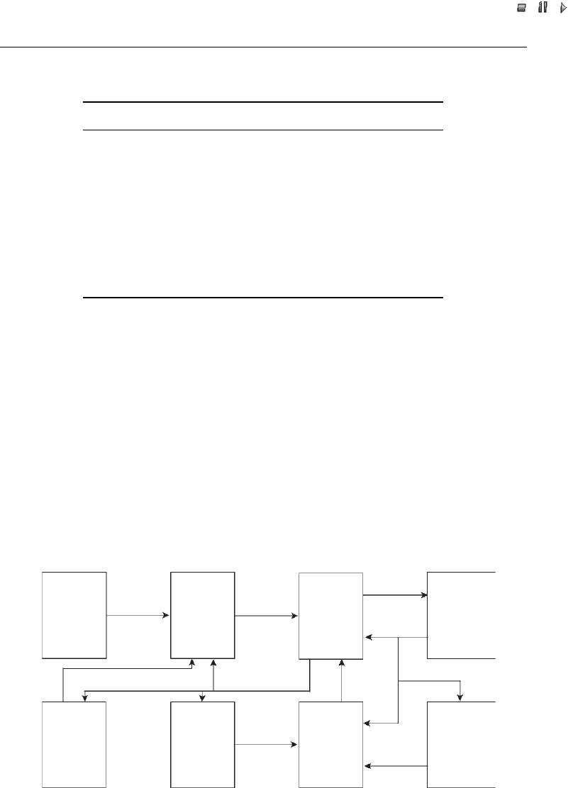
Figure 25.6 depicts the general structure of a model of variable-speed wind turbines with
doubly fed induction generators (Type C). It shows that a wind turbine with a doubly
fed induction generator is much more complex than a con stant-speed wind turbine (see
Figure 25.1). Compared with a constant-speed wind turbine, a variable-speed wind
turbine has additional controllers, such as the rotor speed controller and the pitch angle
controller. Additionally, if it is equipped with terminal voltage control, it also has a
terminal voltage controller. We will now discuss each block in Figure 25.6, with the
Table 25.3 Simulated induction generator parameters
Generator characteristic Value
Number of poles, p 4
Generator speed (constant-speed; rpm) 1517
Generator speed (doubly fed; rpm) 1000–1900
Mutual inductance, L
m
(p.u.) 3.0
Stator leakage inductance, L
s
(p.u.) 0.10
Rotor leakage inductance, L
r
(p.u.) 0.08
Stator resistance, R
s
(p.u.) 0.01
Rotor resistance, R
r
(p.u.) 0.01
Compensating capacitor (constant-speed; p.u.) 0.5
Moment of inertia (s) 0.5
Wind
speed
model or
measured
sequence
Wind
speed
Mechanical
power
Rotor
model
Model of
doubly
fed
induction
generator
Rotor
currents
Active
power
set point
Reactive
power
set point
Active
and
reactive
power
Voltage
and
frequency
Rotor
speed
Pitch
angle
Pitch
angle
controller
Rotor
speed
controller
Terminal
voltage
controller
Fundamental
frequency
grid
model
Converter
and
protection
system
Figure 25.6 General structure of a model of a variable speed wind turbine with doubly fed
induction generator (type C)
Wind Power in Power Systems 567

//INTEGRAS/KCG/P AGIN ATION/ WILEY /WPS /FINALS_1 4-12- 04/0470855088_ 26_CHA25 .3D – 568 – [555–586/32]
17.12.2004 10:50PM
exception of the grid model and the wind speed model. The wind speed model is
identical to that in the constant-speed wind turbine model, described in Section 25.5.2.
The grid model is not discussed for the same reasons mentioned in Section 25.5.1.
Figure 25.6 does not include a shaft model, in contrast to Figure 25.2. The reason
is that in variable-speed wind turbines the mechanical and elect rical part, to a large
extent, are decoupled by the power electronics. Therefore, the control approach of
the power electronics converter determines how the properties and behaviour of the
shaft are reflected in the terminal quantities of the generator. The mutual interde-
pendencies between shaft, control of the power electronic converter and output power
pattern are a very advanced topic which will not be treated here. If it is nevertheless
desired to incorporate a shaft representation in a model of a variable-speed wind
turbine with a doubly fed induction generator, the approach described in Section
25.5.4 can be used.
25.6.2 Rotor model
Again, Equation (25.5) and a numerical approximation of the c
p
(, ) curve based on
Equations (25.6) and (25.7) are used to represent the rotor (see Section 25.5.3). How-
ever, it is assumed here that the variable-speed wind turbine is pitch controlled. The
performance coefficient is thus dependent not only on the tip speed ratio, , but also on
the pitch angle, . Therefore, a new numerical approximation for the c
p
(, ) curve has
been developed, using manufacturer documentation of variable-speed wind turbines and
multidimensional optimisation. Table 25.2 includes the values for the parameters in
Equations (25.6) and (25.7), which are used to represent the rotor of a variable-speed
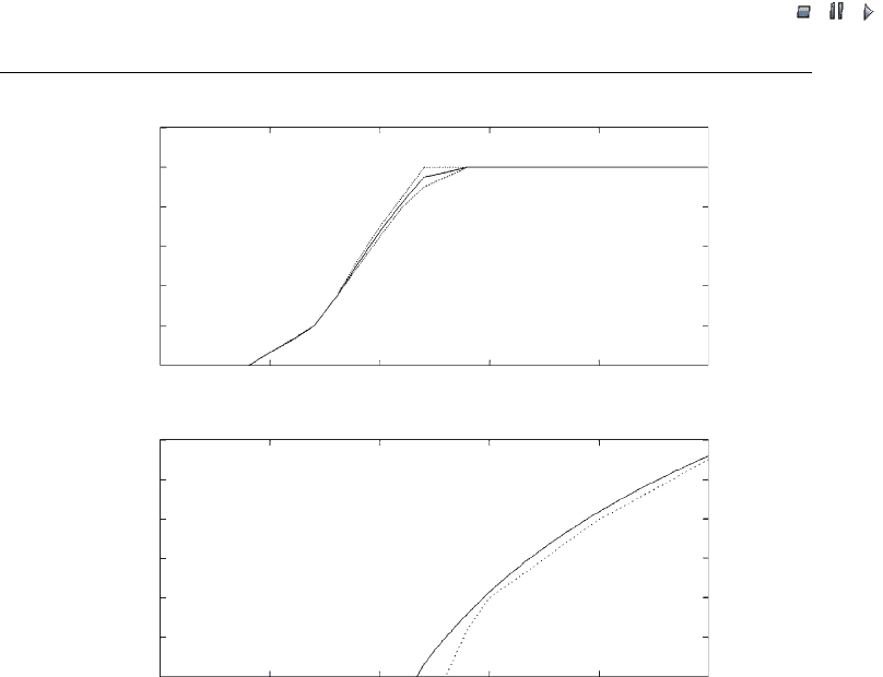
wind turbine. Figure 25.7(a) depicts the resulting power curve, together with the power
curves of two commercial variable-speed wind turbines. Figure 25.7(b) shows the pitch
angle deviation that is necessary to limit the power to the nominal value. In this case,
documentation from only one manufacturer was available.
Again, the rotor model of the simulations includes the low-pass filter depicted in
Figure 25.4 in order to represent the smoothing of high-frequency wind speed compo-
nents over the rotor surface. The simulations are carried out to validate the models and
are described in detail in Section 25.8. This issue is less critical for variable-speed wind
turbines, though, as rapid variations in wind speed are not translated into output power
variations because the rotor functions as an energy buffer. For the same reason,
representation of tower shadow was not included either, because in variable-speed wind
turbines the tower shadow hardly affects the output power because of the decoupling of
electrical and mechanical behaviour by the power electronics (Kru
¨
ger and Andresen,
2001; Petru and Thiringer, 2000).
25.6.3 Generator model
The equations that describe a doubly fed induction generator are identical to those of
the squirrel cage induction generator, [i.e. Equations (25.9) – (25.14); see Section 25.5.5].
The only exception is that the rotor wind ing is not short-circuited. Therefore, in the
expressions for rotor voltages u
dr
and u
qr
in Equations (25.9) and (25.12), these voltages
568 Reduced-order Modelling of Wind Turbines
//INTEGRAS/KCG/P AGIN ATION/ WILEY /WPS /FINALS_1 4-12- 04/0470855088_ 26_CHA25 .3D – 569 – [555–586/32]
17.12.2004 10:50PM
are not equal to zero. The flux equations are identical to those of the squirrel cage
induction generator, given in Equations (25.11).
If we want to obtain the voltage–current relationship using the voltage and flux
linkage equations, first the stator transients must again be neglected. This way, the
generator model corresponds to the assumptions used in PSDSs. This time, we also
neglect the rotor transients (Fujimitsu et al., 2000). To take into account the rotor
transients would require detailed modelling of the converter, including the semiconduc-
tor switches and the current control loops. The result would be time constants that are
significantly lower than 100 ms, the typical minimum time constant studied in PSDSs.
Further, the resul ting model would be much more complex and therefore difficult to use,
and it would require many more parameters, which are often difficult to obtain, in
practice. To avoid this, we assume that the VSCs with current control loops can be
modelled as current sources, as already observed in Section 25.4. Chapter 26 presents a
complete model of the doubly fed induction generator including the stator and rotor
transients.
1.2
1.0
0.8
0.6
0.4
0.2
0
0
51520
25
10
Output power (p.u)
30
25
20
15
10
5
0
0 5 10 15 20 25
Wind speed (m/s)
Wind speed (m/s)
Pitch angle (deg)
(a)
(b)
Figure 25.7 (a) Comparison of the numerical approximation of the power curve of a pitch-
controlled wind turbine (solid curve) with the power curves of two existing pitch-controlled wind
turbines (dotted curves). (b) Pitch angle deviation above nominal wind speed, based on a
numerical approximation (solid curve) and manufacturer documentation (dotted curve)
Wind Power in Power Systems 569

//INTEGRAS/KCG/P AGIN ATION/ WILEY /WPS /FINALS_1 4-12- 04/0470855088_ 26_CHA25 .3D – 570 – [555–586/32]
17.12.2004 10:50PM
The following voltage – current relationships result in per unit quantities:
u
ds
¼R
s
i
ds
þ !
s
½ðL
s
þ L
m
Þi
qs
þ L
m
i
qr
;
u
qs
¼R
s
i
qs
!
s
½ðL
s
þ L
m
Þi
ds
þ L
m
i
dr
;
u
dr
¼R
r
i
dr
þ s!
s
½ðL
r
þ L
m
Þi
qr
þ L
m
i
qs
;
u
qr
¼R
r
i
qr
s!
s
½ðL
r
þ L
m
Þi
dr
þ L
m
i
ds
:
9
>
>
>
>
=
>
>
>
>
;
ð25:16Þ
Note the differences between Equations (25.16) and Equations (25.12): the rotor volt-
ages do not equal zero and the d /dt terms in the rotor equations have been neglected.
The generator parameters are given in Table 25.3.
The equation giving the electrical torque and the equation of motion of a doubly fed
induction generator are again equal to those of a squirrel cage induction generator,
given in Equations (25.13) and (25.14), respectively. The equations for active and
reactive power are, however, different because the rotor winding of the generator can
be accessed. Thi s leads to the incorporation of rotor quantities into these equations:
P ¼ P
s
þ P
r
¼ u
ds
i
ds
þ u
qs
i
qs
þ u
dr
i
dr
þ u
qr
i
qr
;
Q ¼ Q
s
þ Q
r
¼ u
qs
i
ds
u
ds
i
qs
þ u
qr
i
dr
u
dr
i
qr
:
)
ð25:17Þ
It should be emphasised that the reactive power, Q, in Equation (25.17) is not necessar-
ily equal to the reactive power fed into the grid, which is the quantity that must be used
for the load-flow solution. This depends on the control strategy for the grid side of the
power electronic converter that feeds the rotor winding. This does not apply to the
active power. Even though the converter can generate or consume reactive power, it
cannot generate, consume or store active power – at least not long enough to be of any
interest here. The expression for P in Equations (25.17) gives, therefore, the total active
power generated by the doubly fed induction generator, apart from the converter
efficiency, which can be incorporated by multiply ing the last two term s of this expres-
sion (i.e. u
dr
i
dr
and u
qr
i
qr
) with the assumed converter efficiency. That means that all
active power fed into or drawn from the rotor winding will be drawn from or fed into the
grid, respectively.
25.6.4 Converter model
The converter is modelled as a fundamental frequency current source. This assumption
is, however, valid only if the following conditions are fulfilled:
.
the machine parameters are known;
.
the controllers operate in their linear region;
.
vector modulation is used;
.
the terminal voltage approximately equals the nominal value.
The wind turbine manufacturer is responsible for the first two conditions and we assume
that these conditions are fulfilled. The thir d requirement is met, because the control of
the co nverter used in variable-speed wind turbines is ne arly always based on vector
570 Reduced-order Modelling of Wind Turbines