Aiserman M., Gusev L., Rozonoer L., Smirnova l., Tal A. Logic, Automata, and Algorithms
Подождите немного. Документ загружается.

ELEMENTS
OF
MATHEMATICAL
LOGIC
-l-l-l-lo
HUFFMAN‘S METHOD AND REALIZATION
141
cycle timing governed by
the
change of the input. In this
case,
we
would also need
a
synchronous source which would respond to all
change at the input, in order to provide
a
timing signal for the de-
lay elements.
However, the flow table
is
actually the basic table of
a
“fast”
automaton which corresponds to the initial automaton in the sense
that sampling
of
its
stable states gives
a
pattern describing the
operation of that initial automaton (which works in a timing gov-
erned by change of the input).
We
can therefore design from it a “fast”
automaton, corresponding to the initial one, using delay elements,
and thus ensure hazard-free operation. This
is
easier
to accom-
plish, since in
this
case
the construction of the synchronous timing
source
is
simpler.
The Huffman realization
is,
in reality, such
a
procedure.
We
design
a
“fast”
automaton network from the flow table, using de-
lay elements based on relays, and
we
organize
a
relay switching
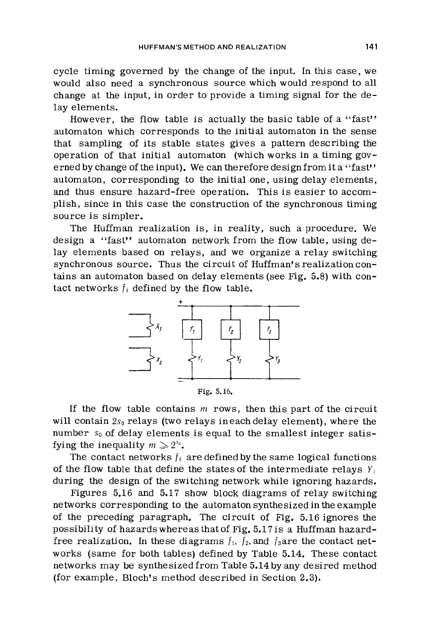
synchronous source. Thus the circuit of Huffman’s realization con-
tains an automaton based on delay elements
(see
Fig.
5.8)
with
con-
tact networks
fi
defined by the flow table.
Fig.
5.16.
If the flow table contains
m
rows, then this part of the circuit
will contain
2sl,
relays
(two relays ineachdelay element), where the
number
SO
of
delay elements
is
equal to the smallest integer satis-
fying
the
inequality
m
>2”.
The contact networks
fi
are defined by the same logical functions
of the flow table that define the statesof
the
intermediate relays
Yi
during the design
of
the switching network
while
ignoring hazards.
Figures 5.16 and 5.17 show block diagrams of relay switching
networks corresponding to the automaton synthesized in the example
of the preceding paragraph.
The circuit of
Fig.
5.16 ignores
the
possibility of hazards
whereas
that of Fig.
5.17is
a
Huffman hazard-
free
realization. In these diagrams
fl,
fz,
and
fsare
the contact net-
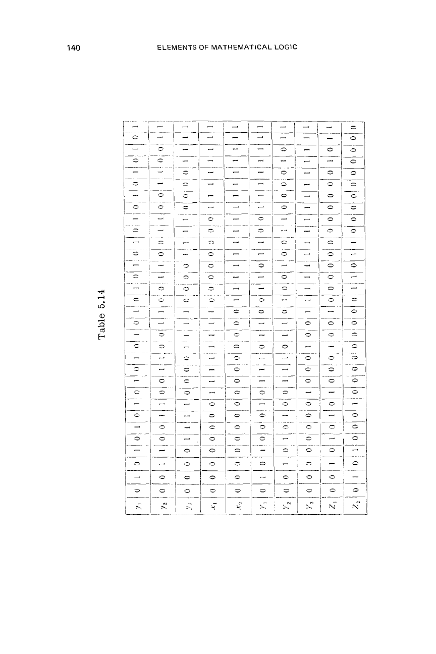
works (same for both tables) defined by Table 5.14. These contact
networks may be synthesized from Table 5.14 by any desired method
(for example, Bloch’s method described in Section
2.3).
142
ELEMENTS
OF
MATHEMATICAL LOGIC
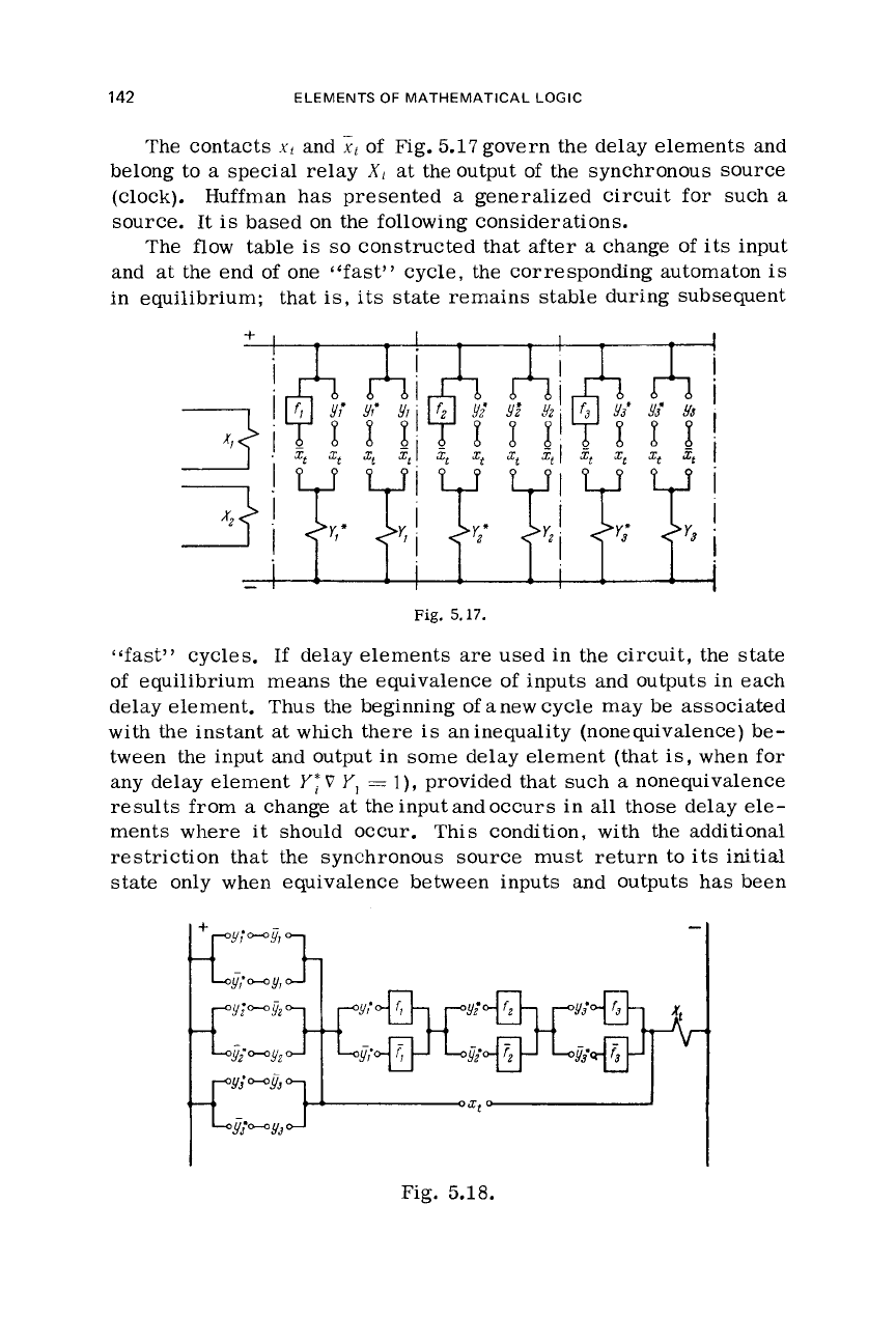
The contacts
xt
and
xl
of Fig.
5.17
govern the delay elements and
belong to
a
special relay
X1
at the output of the synchronous source
(clock). Huffman has presented
a
generalized circuit for such
a
source. It
is
based on the following considerations.
The flow table
is
so
constructed that after
a
change of its input
and at the end of one
“fast”
cycle,
the
corresponding automaton
is
in equilibrium; that
is,
its
state
remains stable during subsequent
+
-
Fig.
5.17.
“fast” cycles.
If
delay elements
are
used in the circuit, the state
of equilibrium means the equivalence of inputs and outputs in each
delay element. Thus the beginning of anew cycle may be associated
with the instant at
which
there
is
aninequality (nonequivalence) be-
tween the input and output in some delay element (that
is,
when for
any delay element
I‘;
V
Y,
=
l),
provided that such
a
nonequivalence
results from a change at the input and occurs in all those delay
ele-
ments
where
it should occur. This condition, with the additional
restriction that the synchronous source must return to
its
initial
state only when equivalence between inputs and outputs
has
been
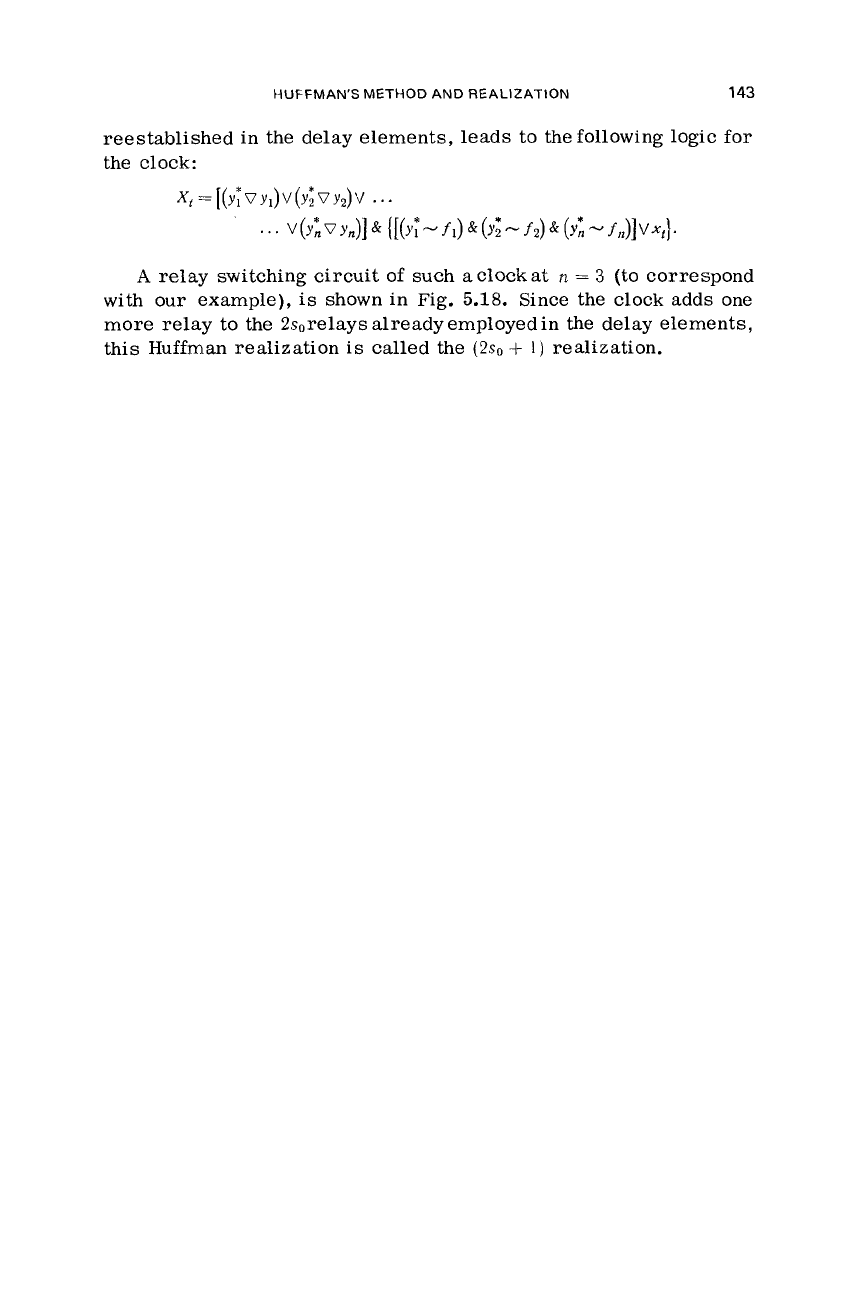
Fig. 5.18.
HUFFMAN'S
METHOD
AND REALIZATION
143
reestablished in the delay elements, leads to the following logic for
the
clock:
Xt=[(Y~VY,)V(Yl~YJ2)V
.
. .
v
(Y*,
v
Y,)]
{
[
(YT'
-
f
l)
&
(Y;
-
f
2)
&
(Y*,
-
f
,*)I
v
+}.
A
relay switching circuit
of
such
a
clock
at
n
=
3
(to correspond
with
our
example),
is
shown in Fig.
5.18.
Since the clock adds one
more relay to the 2sorelays already employed in the
delay
elements,
this
Huffman realization
is
called the
(2so
+
1)
realization.
Autonomous Finite Automata and
Sequential Machines
6.1.
WHAT AUTONOMOUS FINITE AUTOMATA AND
SEQUENTIAL MACHINES “CAN
DO”
This and the following chapter
will
deal with the capabilities of
finite automata and sequential machines.
We
shall establish what
they “can do” and shall determine what
is
in principle beyond the
“capabilities” of any
such
machine. In the present chapter
we
shall
determine the capabilities of the autonomous finite automaton.
Recall that
a
finite automaton
is
autonomous
if
the
variable
p
under function
F
is
fixed. Recall also that from this automaton,
whose equation
is
one can compile
r
different autonomous automata (see Section
3.7)
xP+’
=
F(P,
pP),
2+1=
F(..”
,
PA
(6.1)
because
p.
can coincide with any of the
r
symbols of alphabet
(p}.
The constant
pa
may
be
treated as
a
symbol-parameter.
If
xn
is
given, then by virtue of
(6.1)
we
can find
xl.
Then, sub-
stituting
XI
into
(6.1),
we
can determine
x2,
and
so
on. Thus, an au-
tonomous finite automaton started at some initial symbol
xo
can
generate
an
infinite sequence of symbols
x:
KO,
./?,
72,
.
. .
,
7.P,
.
.
.
The number of symbols in alphabet
(x}
is
finite and equal to
k.
For
this reason, the automaton will generate, after
a
finite number
of time units
q
(9
,<
k),
a
symbol, that
has
already appeared in the
sequence, for example, the symbol
x6
in the sequence
x2%3x(jx5x4x7xG
.
.
.
Thus, from thejq
+
1)-th timeunitonward, the automaton
will
simply
periodically repeat this symbol sequence
(the
sequence of
our
ex-
ample
is
x~x~x(j.~~~4x7x~~jy$~7~~~j%~.~7
.
.
.
where the recurring sequence
1s
underlined)
.
f
44
WHAT AUTONOMOUS FINITE AUTOMATA "CAN
DO"
145
It follows that
an
autonomous automaton, startedup
at
any initial
state
will,
after
at
most
k
time units, periodically repeat
a
sequence
of symbols
x
(whose length does not exceed
k).
With any other
initial
state, this automaton would also periodically repeat a sequence of
symbols
x
after
some time. However, this sequence may not coin-
cide with that generated before.
A
special
case
occurs when the sequence consists
of
a
simple
symbol.
This
will
occur when, for example,
or
A
symbol that appears twice in succession in a sequence shall
be called
a
stable
symbol.
We
shall say that the automaton becomes
stable during the time unit in which the stable symbol first appears.
Symbol
xj
is
stable
if
that is,
at
p
=
p.::,
symbol
?c,
is
translated by Eq. (6.1) into itself.
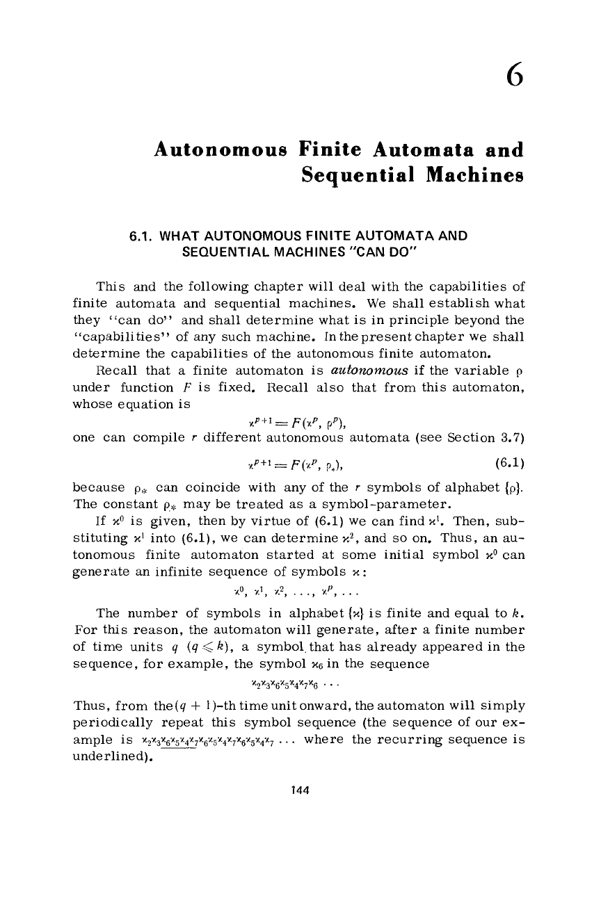
All
these statements
are
illustrated by the diagram of the au-
tonomous automaton. This diagram contains
k
circles, correspond-
ing
to
all
the possible
symbols
x
that can be generated. Several
arrows may converge on each circle, but only one may be drawn
from it. For this reason,
if
we
proceed in the direction of the
ar-
rows,
we
are
bound to return after no more than
k
steps to one of
the
circles
previously crossed (the arrows form
a
cycle,
Fig. 6.1),
or, alternatively,
we
shall arrive to
a
circle
at which the leaving
arrow forms
a
loop, that is, indicates equilibrium
(see
Fig. 6.2).
Figure 6.3 shows various diagrams for
k
=
12.
In the
case
of Fig. 6.3, the cycle involves
all
the available
circles.
Here
the machine generates from the outset
a
periodically
b
Fig.
6.1.
Fig.
6.2.

146
ELEMENTS OF MATHEMATICAL LOGIC
recurring sequence consisting
of
all
k
symbols.* The
initial
state
determines only the order of the symbols in the sequence.
In Fig. 6.3,b the cycleencompasses onlyfive circles; the arrows
drawn from the remaining circles converge on one of the circles
of
the cycle.
Here
the automaton generates
a
sequence of length
5;
this sequence will be generated after
a
maximum
of
one time unit,
regardless of the initial state of the automaton.
For
the
case
of
Fig. 6.3,~ the maximum number of time units
preceding the generation
of
the periodic sequence
is
four.
Figure 6.3,d shows an autonomous automaton that, depending on
its initial state, generates one of three sequences
(of
lengths
2,
3,
and
5,
respectively).
The automaton of Fig. 6.3,e can, depending on its initial state,
either attain equilibrium after
a
maximum
of
three time units,
or
Fig.
6.3.
*In this and the
following
case we are assuming that it
is
immaterial what the
initial
symbol
of
the sequence
is.
WHAT AUTONOMOUS FINITE AUTOMATA "CAN
DO"
147
can start to generate periodic sequence
of
length 4 after
a
maximum
of one time unit.
Finally, Fig. 6.3,f shows an autonomous automaton with three
equilibrium states: depending
on
its initial state, some equilibrium
is
attained in at most two discrete time units.
If
we
want to synthesize an autonomous automaton generating
a
periodic sequence of some given length
q
andwe impose some addi-
tional conditions
as
to the time preceding the generation
of
this
sequence,
all
we
need to do
is
to
draw
a
diagram satisfying these
conditions. This
is
because the diagram defines the autonomous
automaton uniquely [the basic table can be directly reconstructed
from it (Chapter
3)].
Suppose that we want to generate periodic sequences
of
lengths
2,
4,
and 6. Which of the sequences shall be generated shall be de-
termined by the initial state
of
the
automaton; in no case can the
generation of the sequence begin later than one time unit after start
UP.
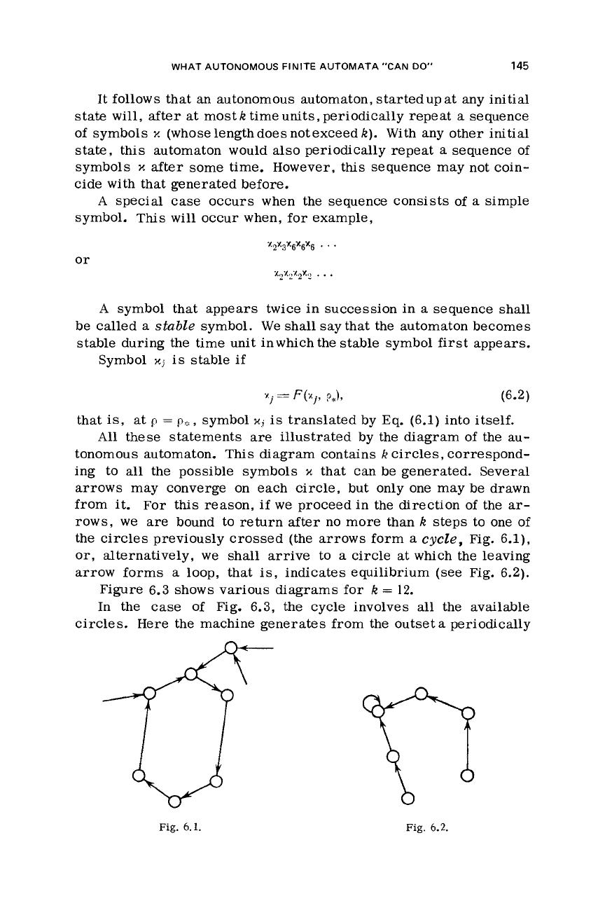
The minimum
k
satisfying these conditions
is
12.
If
h
=
12
(Fig.
6.4), then the appropriate diagram
is
drawn by joining into cycles
any of
two,
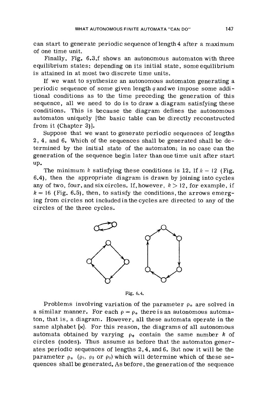
four,andsixcircles. If,however,
k
>
12,
for example,
if
k
=
16
(Fig. 6.5), then,
to
satisfy the conditions, the arrows emerg-
ing from
circles
not included in the cycles
are
directed
to
any of the
circles
of the three cycles.
Fig.
6.4.
Problems involving variation
of
the parameter
p.
are
solved in
a
similar manner. For
each
p
=
p*
there
is
an autonomous automa-
ton, that
is,
a
diagram. However,
all
these automata operate in the
same alphabet
{x).
For this reason, the diagramsof
all
autonomous
automata abtained by varying
p*
contain the same number
k
of
circles
(nodes). Thus assume
as
before that the automaton gener-
ates periodic sequences
of
lengths
2,4,
and 6. But now it
will
be
the
parameter
p:%
(PI,
pz
or
p3)
which
will
determine which of these
se-
quences shall be generated.
As
before, the generation
of
the sequence
148
ELEMENTS
OF
MATHEMATICAL
LOGIC
at any
up of the automaton.
shall begin no later than one discrete time unit after start
Fig. 6.5. Fig.
6.6.
Obviously,
k
must be at least equal to the length of the longest
given sequence;
otherwise it
would
be impossible to design an
au-
tonomous automaton generating that sequence
at
any
p.
Now,
as-
suming, for example, that
k
=
6,
we
constructadiagram for
p*
=
p3
(Fig. 6.6), connecting
all
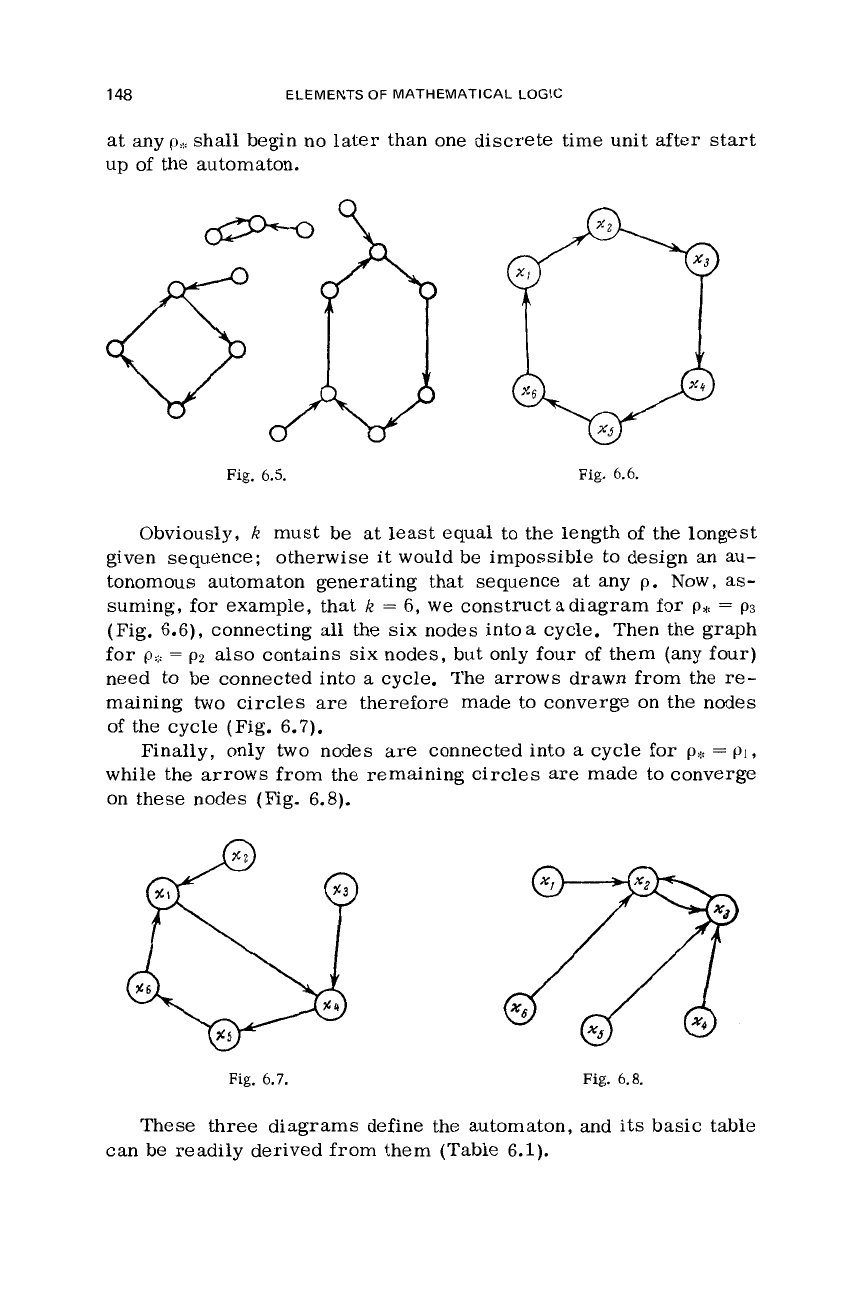
the six nodes intoa cycle. Then the graph
for
Q:::
=
p2
also contains
six
nodes, but only
four
of
them (any four)
need to be connected into
a
cycle.
The arrows drawn
from
the
re-
maining
two
circles
are
therefore made to converge on the nodes
of the cycle (Fig. 6.7).
Finally, only two nodes
are
connected into
a
cycle
for
ph-
=
pl
,
while the arrows from the remaining circles
are
made to converge
on these nodes
(Fig.
6.8).
Fig.
6.7.
Fig.
6.8.
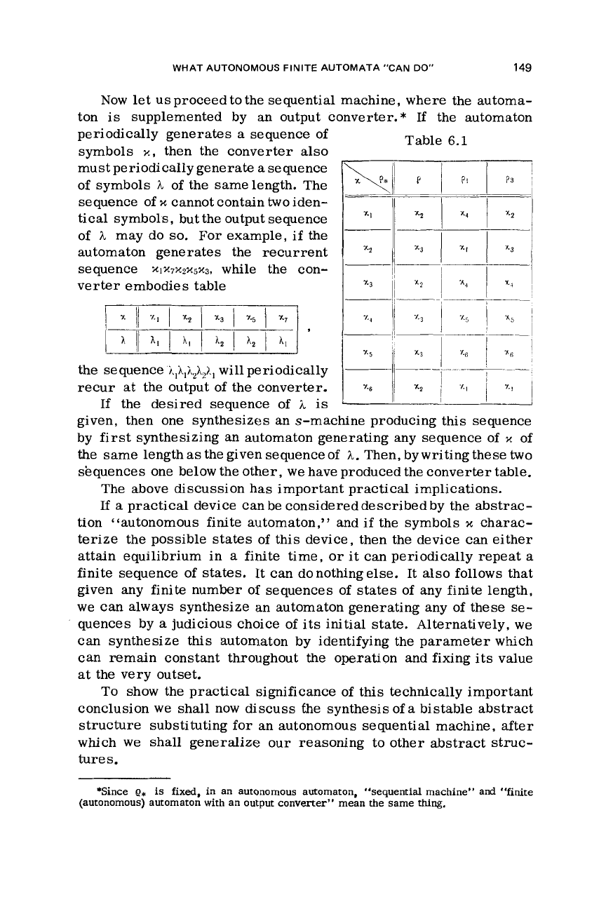
These three diagrams define the automaton, and
its
basic table
can be readily derived from them (Table 6.1).
WHAT AUTONOMOUS FINITE AUTOMATA “CAN
DO”
149
Now
let
us proceed to
the
sequential machine, where the automa-
ton
is
supplemented by
an
output converter.* If the automaton
periodically generates
a
sequence of
symbols
X,
then the converter also
must periodically generate
a
sequence
of symbols
h
of the samelength. The
sequence
of
x
cannot contain
two
iden-
of
h
may do
so.
For
example,
if
the
Table
6.1
tical
symbols, buttheoutputsequence
automaton generates the recurrent
sequence
xIx7X2X5X3,
while
the
con-
verter embodies table
___
the
sequence
I&&
will periodically
If the desired sequence of
iL
is
~
__---
-
-
~
-
recur at the output of
the
converter.
I
y6
1
xZ
~
’I
i
’I
1
given, then one synthesizes an s-machine producing
this
sequence
by first synthesizing an automaton generating any sequence of
x
of
the same length
as
the given sequence of
h.
Then, by writing
these
two
sequences one below the other, we have produced the converter table.
The above discussion has important practical implications.
If
a
practical device can be considered described by
the
abstrac-
tion “autonomous
finite
automaton,” and
if
the
symbols
x
charac-
terize the possible
states
of this device, then the device can either
attain equilibrium in
a
finite time,
or
it
can periodically repeat
a
finite sequence of states.
It
can donothingelse. It also follows that
given any finite number
of
sequences
of
states
of any
finite
length,
we
can always synthesize
an
automaton generating any of these
se-
quences by
a
judicious choice of its initial state. Alternatively,
we
can synthesize
this
automaton by identifying the parameter which
can remain constant throughout the operation and fixing
its
value
at
the very outset.
To show the practical significance of
this
technically important
conclusion
we
shall now discuss the synthesis of
a
bistable abstract
structure substituting for an autonomous sequential machine, after
which
we
shall generalize our reasoning to other abstract struc-
tures.
*Since
e,
is
fixed, in an autonomous automaton, “sequential machine” and “finite
(autonomous) automaton with an output converter” mean the same
thing.