ALSTOM T&D. Network Protection And Automation Guide (NPAG)
Подождите немного. Документ загружается.

i. Alstom Grid
-i
© 2011 Alstom Grid. Single copies of this document may be filed or printed for personal non-commercial use and must include this
copyright notice but may not be copied or displayed for commercial purposes without the prior written permission of Alstom Grid.
Network Protection & Automation Guide
-ii
Network Protection & Automation
Guide
NETWORK PROTECTION & AUTOMATION
GUIDE, EDITION MAY 2011
Previously called Protective Relays Application Guide
First Edition June 1966
Reprinted January 1967
August 1968
November 1970
September 1971
February 1973
January 1974
Second Edition March 1975
Reprinted November 1977
December 1979
November 1982
October 1983
October 1985
Third Edition June 1987
Reprinted September 1990
March 1995
Network Protection & Automation Guide
First Edition July 2002
©
2011 ALSTOM GRID MAY 2011
ISBN: 978-0-9568678-0-3
Published by Alstom Grid
Alstom Grid Worldwide Contact Centre
www.alstom.com/grid/contactcentre
Tel: +44(0) 1785 250 070
www.alstom.com/grid/sas
All rights reserved. Celebrating 45 years of PRAG/NPAG and 54th APPS course.
© 2011 Alstom Grid. Single copies of this document may be filed or printed for personal non-commercial use and must include this
copyright notice but may not be copied or displayed for commercial purposes without the prior written permission of Alstom Grid.
Network Protection & Automation Guide
-iii
CONTENTS
1 Introduction
2 Fundamentals of Protection Practice
3 Fundamental Theory
4 Fault Calculations
5
Equivalent Circuits and Parameters of
Power System Plant
6 Current and Voltage Transformers
7 Relay Technology
8 Protection: Signalling and Intertripping
9
Overcurrent Protection for Phase and
Earth Faults
10 Unit Protection of Feeders
11 Distance Protection
12 Distance Protection Schemes
13
Protection of Complex Transmission
Circuits
14 Auto-Reclosing
15 Busbar Protection
16
Transformer and Transformer-Feeder
Protection
17
Generator and Generator-Transformer
Protection
18
Industrial and Commercial Power System
Protection
19 A.C. Motor Protection
20 System Integrity Protection Schemes
21 Relay Testing and Commissioning
22 Power System Measurements
23 Power Quality
24 The Digital Substation
25 Substation Control and Automation
Appendix A Terminology
Appendix B IEEE/IEC Relay Symbols
Appendix C
Typical Standards Applicable to
Protection and Control Numerical Devices
Appendix D Company Data and Nomenclature
Index
© 2011 Alstom Grid. Single copies of this document may be filed or printed for personal non-commercial use and must include this
copyright notice but may not be copied or displayed for commercial purposes without the prior written permission of Alstom Grid.

© 2011 Alstom Grid. Single copies of this document may be filed or printed for personal non-commercial use and must include this
copyright notice but may not be copied or displayed for commercial purposes without the prior written permission of Alstom Grid.
Alstom Grid 1-1
Chapter 1
Introduction
Since 1966, the Network Protection and Automation Guide
(formerly the Protective Relays Application Guide) has been
the definitive reference textbook for protection engineers and
technicians. For 2011, Alstom has capitalised on its pool of
experts at the St Leonards Centre of Excellence in Stafford UK
to launch a new edition.
New chapters treat topics such as system integrity protection
and remedial action schemes, phasor measurements and wide
area schemes. The digital substation, including IEC 61850,
Ethernet station bus, GOOSE, process bus, and precision time
synchronising is also detailed. Advancements in protection
and control application engineering have assisted the authors
in exploring and integrating the new techniques and
philosophies in this edition, whilst retaining vendor-
independence – as we continue to deliver the genuine,
impartial, reference textbook.
This book is a précis of the Application and Protection of Power
Systems (APPS) training course, an intensive programme,
which Alstom (and its predecessor companies at Stafford) has
been running for over 50 years. This course, by the ingenuity
and dedication of the trainers, is vibrant and evolving. As
APPS progresses, the Network Protection and Automation
Guide advances too, whilst never losing sight of the key basic
principles and concepts. Beginners and experts alike will each
feel satisfied in their search for relaying, measurement,
communication and control knowledge.
In the list opposite, we name a mix of new authors for this
edition, and key historical figures at Stafford who have
contributed significantly to the advancement of APPS and
NPAG, and hence the quality and integrity of our book. We
sincerely hope that this book assists your navigation through a
challenging and rewarding career in electrical power
engineering. Protection and control has long been termed an
art, rather than a precise science - this book offers a mix of
both.
We acknowledge and thank Alstom colleagues in the wider
Alstom Grid and Alstom Power organisations for photographs
used within this book.
.
Michael Bamber
Michael Bergstrom
Andrew Darby
Susan Darby
Graham Elliott
Peter Harding
Graeme Lloyd
Alan Marshall
Allen Millard
Andrew Myatt
Philip Newman
Anthony Perks
Steve Pickering
Stephen Potts
Simon Richards
Jack Royle
Peter Rush
Brendan Smith
Mark Stockton
Paul Wilkinson
Alan Wixon
John Wright
© 2011 Alstom Grid. Single copies of this document may be filed or printed for personal non-commercial use and must include this
copyright notice but may not be copied or displayed for commercial purposes without the prior written permission of Alstom Grid.
© 2011 Alstom Grid. Single copies of this document may be filed or printed for personal non-commercial use and must include this
copyright notice but may not be copied or displayed for commercial purposes without the prior written permission of Alstom Grid.
Alstom Grid 2-1
Chapter 2
Fundamentals of Protection Practice
2.1 Introduction
2.2 Protection Equipment
2.3 Zones of Protection
2.4 Reliability
2.5 Selectivity
2.6 Stability
2.7 Speed
2.8 Sensitivity
2.9 Primary and Back-up Protection
2.10 Relay Output Devices
2.11 Tripping Circuits
2.12 Trip Circuit Supervision
2.1 INTRODUCTION
The purpose of an electrical power system is to generate and
supply electrical energy to consumers. The system should be
designed to deliver this energy both reliably and economically.
Frequent or prolonged power outages result in severe
disruption to the normal routine of modern society, which is
demanding ever-increasing reliability and security of supply.
As the requirements of reliability and economy are largely
opposed, power system design is inevitably a compromise.
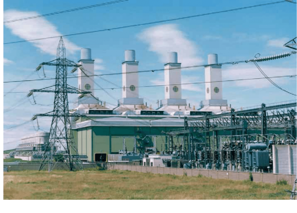
A power system comprises many diverse items of equipment.
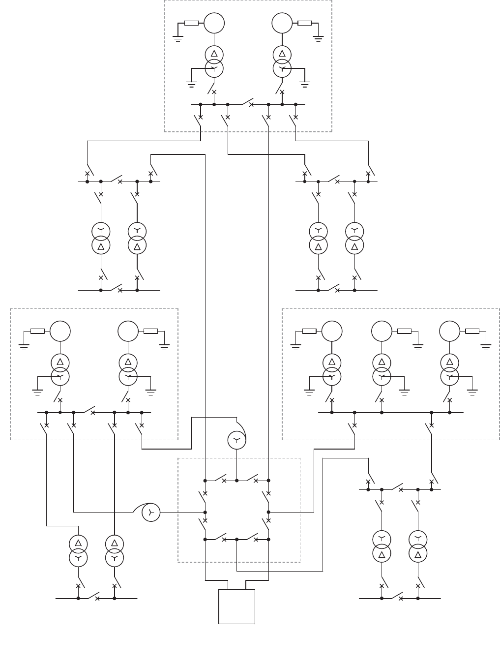
Figure 2.1 illustrates the complexity of a typical power station
Figure 2.2 shows a hypothetical power system.
Figur
e
2
.
1
: Modern power statio
n
© 2011 Alstom Grid. Single copies of this document may be filed or printed for personal non-commercial use and must include this
copyright notice but may not be copied or displayed for commercial purposes without the prior written permission of Alstom Grid.
Network Protection & Automation Guide
2-2
Figure
2
.
2
: Exampl
e
power syste
m
R
1
GS
G
1
T
1
G
2
T
2
R
2
GS
A
380kV
Hydro power station
380kV
B
L
1A
L
1B
380kV
C
L
2
L
3
L
4
T
4
B'
T
3
33kV
T
5
T
6
110kV C'
380kV
CCGT power station
T
8
T
7
E
G
5
R
5
GS
G
6
GS
R
6
GS
G
7
R
7
T
9
D
220kV
Steam power station
R
3
GS
GS
T
10
T
11
G
3
G
4
R
4
L
7A
Grid
Substation
T
14
T
15
L
7B
33kV D'
T
12
T
13
110kV
380kV
L
8
G'
G
T
16
T
17
L
5
Grid
380kV
F '
F
L
6
Key
GS: Generator
T: Transformer
R: Resistor
L: Line
© 2011 Alstom Grid. Single copies of this document may be filed or printed for personal non-commercial use and must include this
copyright notice but may not be copied or displayed for commercial purposes without the prior written permission of Alstom Grid.
Chapter 2Fundamentals of Protection Practice
2-3
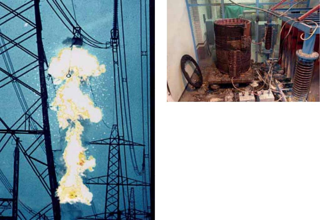
Figure 2.3: Onset of an overhead line fault
Many items of equipment are very expensive, and so the
complete power system represents a very large capital
investment. To maximise the return on this outlay, the system
must be utilised as much as possible within the applicable
constraints of security and reliability of supply. More
fundamental, however, is that the power system should
operate in a safe manner at all times. No matter how well
designed, faults will always occur on a power system, and
these faults may represent a risk to life and/or property. Figure
2.3 shows the onset of a fault on an overhead line. The
destructive power of a fault arc carrying a high current is very
large; it can burn through copper conductors or weld together
core laminations in a transformer or machine in a very short
time – some tens or hundreds of milliseconds. Even away
from the fault arc itself, heavy fault currents can cause
damage to plant if they continue for more than a few seconds.
The provision of adequate protection to detect and disconnect
elements of the power system in the event of fault is therefore
an integral part of power system design. Only by doing this
can the objectives of the power system be met and the
investment protected. Figure 2.4 provides an illustration of the
consequences of failure to provide adequate protection. This
shows the importance of protection systems within the
electrical power system and of the responsibility vested in the
Protection Engineer.
Figure 2.4: Possible consequence of inadequate protection
2.2 PROTECTION EQUIPMENT
The definitions that follow are generally used in relation to
power system protection:
x Protection System: a complete arrangement of
protection equipment and other devices re
quired to
achieve a specified function based on a protection
principle (IEC 60255-20)
x Protection Equipment: a collection of protection
devices (relays, fuses, etc.). Excluded are devices such
as Current Transformers
(CTs), Circuit Breakers (CBs)
and contactors
x Protection Scheme: a collection of protection
equipment providing a defined function and including
all equipment required to make the scheme work (i.e.
relays, CTs, CBs, batteries, etc.)
In order to fulfil the requirements of protection with the
optimum speed for the many different configurations,
operating conditions and construction features of power
systems, it has been necessary to develop many types of relay
that respond to various functions of the power system
quantities. For example, simple observation of the fault
current magnitude may be sufficient in some cases but
measurement of power or impedance may be necessary in
others. Relays frequently measure complex functions of the
system quantities, which may only be readily expressible by
mathematical or graphical means.
Relays may be classified according to the technology used:
x electromechanical
x static
x digital
x numerical
The different types have varying capabilities, according to the
limitations of the technology used. They are described in
more
detail in Chapter 7.
© 2011 Alstom Grid. Single copies of this document may be filed or printed for personal non-commercial use and must include this
copyright notice but may not be copied or displayed for commercial purposes without the prior written permission of Alstom Grid.
Network Protection & Automation Guide
2-4
In many cases, it is not feasible to protect against all hazards
with a relay that responds to a single power system quantity.
An arrangement using several quantities may be required. In
this case, either several relays, each responding to a single
quantity, or, more commonly, a single relay containing several
elements, each responding independently to a different
quantity may be used.
The terminology used in describing protection systems and
relays is provided in Appendix A. Different symbols for
describing relay functions in diagrams of protection schemes
are used, the three most common methods (IEC, IEEE/ANSI
and IEC61850) are provided in Appendix B.
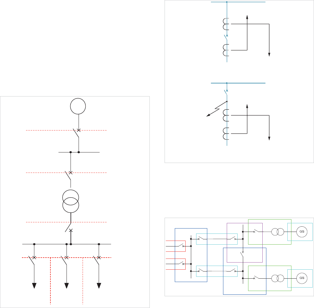
2.3 ZONES OF PROTECTION
To limit the extent of the power system that is disconnected
when a fault occurs, protection is arranged in zones. The
principle is shown in Figure 2.5. Ideally, the zones of
protection should overlap, so that no part of the power system
is left unprotected. This is shown in Figure 2.6(a), the circuit
breaker being included in both zones.
GS
Feeder 2Feeder 1
Feeder 3
Zone 6
Zone 5 Zone 7
Zone 4
Zone 3
Zone 2
Zone 1
Figure 2.5: Division of power systems into protection zones
For practical physical and economic reasons, this ideal is not
always achieved, accommodation for current transformers
being in some cases available only on one side of the circuit
breakers, as shown in Figure 2.6(b). In this example, the
section between the current transformers and the circuit
breaker A is not completely protected against faults. A fault at
F would cause the busbar protection to operate and open the
circuit breaker but the fault may continue to be fed through the
feeder. If the feeder protection is of the type that responds
only to faults within its own zone (see section 2.5.2), it would
not operate, since the fault is outside its zone. This problem is
dealt with by intertripping or some form of zone extension, to
ensure that the remote end of the feeder is also tripped. These
methods are explained extensively in chapters 11 and 12.
A
F
F
Feeder
protection
Feeder
p
rotection
Busbar
protection
Busbar
protection
(
a) CTs on both sides of circuit breaker
(
b)CTs on circuit side of circuit breake
r
Figure 2.6: CT locations
The point of connection of the protection with the power
system usually defines the zone and corresponds to the
location of the current transformers. Unit type protection
results in the boundary being a clearly defined closed loop.
Figure 2.7 shows a typical arrangement of overlapping zones.
Figure 2.7: Overlapping zones of protection systems
Alternatively, the zone may be unrestricted; the start will be
defined but the extent (or ‘reach’) will depend on
measurement of the system quantities and will therefore be
subject to variation, owing to changes in system conditions
and measurement errors.
© 2011 Alstom Grid. Single copies of this document may be filed or printed for personal non-commercial use and must include this
copyright notice but may not be copied or displayed for commercial purposes without the prior written permission of Alstom Grid.