API RP 2A-WSD-2007 Recommended Practice for Planning, Designing and Constructing Fixed Offshore Platforms-Working Stress Design
Подождите немного. Документ загружается.


RECOMMENDED PRACTICE FOR PLANNING, DESIGNING AND CONSTRUCTING FIXED OFFSHORE PLATFORMS—WORKING STRESS DESIGN 9
1.7.1.a L-1 Manned-nonevacuated
The manned-nonevacuated category refers to a platform
that is continuously occupied by persons accommodated and
living thereon, and personnel evacuation prior to the design
environmental event is either not intended or impractical.
1.7.1.b L-2 Manned-evacuated
The manned-evacuated category refers to a platform that is
normally manned except during a forecast design environmen-
tal event. For categorization purposes, a platform should be
classified as a manned-evacuated platform if, prior to a design
environmental event, evacuation is planned and sufficient time
exists to safely evacuate all personnel from the platform.
1.7.1.c L-3 Unmanned
The unmanned category refers to a platform that is not nor-
mally manned, or a platform that is not classified as either
manned-nonevacuated or manned-evacuated. Platforms in
this classification may include emergency shelters. However,
platforms with permanent quarters are not defined as
unmanned and should be classified as manned-nonevacuated
or as manned-evacuated as defined above. An occasionally
manned platform could be categorized as unmanned in cer-
tain conditions (see Commentary C1.7.1c).
1.7.2 Consequence of Failure
As stated above, consequences of failure should include
consideration of anticipated losses to the owner, the other
operators, and the industry in general. The following descrip-
tions of relevant factors serve as a basis for determining the
appropriate level for consequence of failure.
1.7.2.a L-1 High Consequence
The high consequence of failure category refers to major
platforms and/or those platforms that have the potential for
well flow of either oil or sour gas in the event of platform fail-
ure. In addition, it includes platforms where the shut-in of the
oil or sour gas production is not planned, or not practical prior
to the occurrence of the design event (such as areas with high
seismic activity). Platforms that support major oil transport
lines (see Commentary C1.7.2—Pipelines) and/or storage
facilities for intermittent oil shipment are also considered to
be in the high consequence category. All new U.S. Gulf of
Mexico platforms which are designed for installation in water
depths greater than 400 feet are included in this category
unless a lower consequence of failure can be demonstrated to
justify a reduced classification.
1.7.2.b L-2 Medium Consequence
The medium consequence of failure category refers to plat-
forms where production would be shut-in during the design
event. All wells that could flow on their own in the event of
platform failure must contain fully functional, subsurface
safety valves, which are manufactured and tested in accor-
dance with the applicable API specifications. Oil storage is
limited to process inventory and “surge” tanks for pipeline
transfer.
1.7.2.c L-3 Low Consequence
The low consequence of failure category refers to minimal
platforms where production would be shut-in during the
design event. All wells that could flow on their own in the
event of platform failure must contain fully functional, subsur-
face safety valves, which are manufactured and tested in
accordance with applicable API specifications. These plat-
forms may support production departing from the platform
and low volume infield pipelines. Oil storage is limited to pro-
cess inventory. New U.S. Gulf of Mexico platforms in this cat-
egory include caissons and small well protectors with no more
than five well completions either located on or connected to
the platform and with no more than two pieces of production
equipment. In addition, platforms in this category are defined
as structures in water depths not exceeding 100 feet.
1.8 PLATFORM REUSE
Existing platforms may be removed and relocated for con-
tinued use at a new site. When this is to be considered, the
platform should be inspected to ensure that it is in (or can be
returned to) an acceptable condition. In addition, it should be
reanalyzed and reevaluated for the use, conditions, and load-
ing anticipated at the new site. In general, this inspection,
reevaluation, and any required repairs or modification should
follow the procedures and provisions for new platforms that
are stated in this recommended practice. Additional special
provisions regarding reuse are listed in Section 15.
1.9 PLATFORM ASSESSMENT
An assessment to determine fitness for purpose may be
required during the life of a platform. This procedure is nor-
mally initiated by a change in the platform usage such as
revised manning or loading, by modifications to the condition
of the platform such as damage or deterioration, or by a
reevaluation of the environmental loading or the strength of
the foundation. General industry practices recognize that
older, existing structures may not meet current design stan-
dards. However, many of these platforms that are in an
acceptable condition can be shown to be structurally adequate
using a risk-based assessment criteria that considers platform
use, location, and the consequences of failure.
For platforms which were designed in accordance with the
provisions of the 20th and earlier editions, as well as plat-
forms designed prior to the first edition of this publication,
recommendations regarding the development of reduced cri-
00
00
00
00
Copyright American Petroleum Institute
Provided by IHS under license with API
Licensee=Indonesia location/5940240008
Not for Resale, 10/22/2008 00:07:12 MDT
--`,,```,,,`,,,,,,,,,,,,,,`,``,`-`-`,,`,,`,`,,`---

10 API RECOMMENDED PRACTICE 2A-WSD
teria for assessment considering life-safety and consequences
of failure as well as for assessment procedures are included in
Section 17. These fitness for purpose provisions shall not be
used to circumvent normal design practice requirements
when designing new platforms. The reduced environmental
criteria as defined in Section 17 should not be utilized to jus-
tify modifications or additions to a platform that will result in
an increased loading on the structure for platforms that have
been in service less than five years.
Assessment of platforms designed in accordance with pro-
visions of the 21st Edition and later editions of this publica-
tion should be performed using the environmental criteria
originally used for the design, unless a special study can jus-
tify a reduction in Exposure Category as defined in Section 1.
1.10 SAFETY CONSIDERATIONS
The safety of life and property depends upon the ability of
the structure to support the loads for which it was designed,
and to survive the environmental conditions that may occur.
Over and above this overall concept, good practice dictates
use of certain structural additions, equipment and operating
procedures on a platform so that injuries to personnel will be
minimized and the risk of fire, blast and accidental loading
(for example, collision from ships, dropped objects) is
reduced. Governmental regulations listed in Section 1.11 and
all other applicable regulations should be met.
1.11 REGULATIONS
Each country has its own set of regulations concerning off-
shore operations. Listed below are some of the typical rules
and regulations that, if applicable, should be considered when
designing and installing offshore platforms in U.S. territorial
waters. Other regulations may also be in effect. It is the
responsibility of the operator to determine which rules and
regulations are applicable and should be followed, depending
upon the location and type of operations to be conducted.
1. 33 Code of Federal Regulations Chapter N, Parts 140 to
147, “Outer Continental Shelf Activities,” U.S. Coast Guard,
Department of Transportation. These regulations stipulate
requirements for identification marks for platforms, means of
escape, guard rails, fire extinguishers, life preservers, ring
buoys, first aid kits, etc.
2. 33 Code of Federal Regulations Part 67, “Aids to Naviga-
tion on Artificial Islands and Fixed Structures,” U.S. Coast
Guard, Department of Transportation. These regulations pre-
scribe in detail the requirements for installation of lights and
foghorns on offshore structures in various zones.
3. 30 Code of Federal Regulations Part 250, Minerals Man-
agement Service (formerly U.S. Geological Service), OCS
Regulations. These regulations govern the marking, design,
fabrication, installation, operation, and removal of offshore
structures and related appurtenances.
4. 29 Code of Federal Regulations Part 1910, Occupational
Safety and Health Act of 1970. This act specifies require-
ments for safe design of floors, handrails, stairways, ladders,
etc. Some of its requirements may apply to components of
offshore structures that are located in state waters.
5. 33 Code of Federal Regulations Part 330, “Permits for
Work in Navigable Waters,” U.S. Corps of Engineers.
Nationwide permits describes requirements for making appli-
cation for permits for work (for example, platform installa-
tion) in navigable waters. Section 10 of the River and Harbor
Act of 1899 and Section 404 of the Clean Water Act apply to
state waters.
6. Obstruction Marking and Lighting, Federal Aviation
Administration. This booklet sets forth requirements for
marking towers, poles, and similar obstructions. Platforms
with derricks, antennae, etc., are governed by the rules set
forth in this booklet. Additional guidance is provided by API
Recommended Practice 2L, Recommended Practice for Plan-
ning, Designing, and Constructing Heliports for Fixed Off-
shore Platforms.
7. Various state and local agencies (for example, U.S.
Department of Wildlife and Fisheries) require notification of
any operations that may take place under their jurisdiction.
Other regulations concerning offshore pipelines, facilities,
drilling operations, etc., may be applicable and should be
consulted.
2 Design Criteria and Procedures
2.1 GENERAL
2.1.1 Dimensional System
All drawings, calculations, etc., should be consistent in one
dimensional system, such as the English dimensional system
or the SI metric system.
2.1.2 Definition of Loads
2.1.2.a General
The following loads and any dynamic effects resulting
from them should be considered in the development of the
design loading conditions in 2.2.1.
2.1.2.b Dead Loads
Dead loads are the weights of the platform structure and
any permanent equipment and appurtenant structures which
do not change with the mode of operation. Dead loads should
include the following:
00
Copyright American Petroleum Institute
Provided by IHS under license with API
Licensee=Indonesia location/5940240008
Not for Resale, 10/22/2008 00:07:12 MDT
--`,,```,,,`,,,,,,,,,,,,,,`,``,`-`-`,,`,,`,`,,`---

RECOMMENDED PRACTICE FOR PLANNING, DESIGNING AND CONSTRUCTING FIXED OFFSHORE PLATFORMS—WORKING STRESS DESIGN 11
1. Weight of the platform structure in air, including where
appropriate the weight of piles, grout and ballast.
2. Weight of equipment and appurtenant structures perma-
nently mounted on the platform.
3. Hydrostatic forces acting on the structure below the water-
line including external pressure and buoyancy.
2.1.2.c Live Loads
Live loads are the loads imposed on the platform during its
use and which may change either during a mode of operation
or from one mode of operation to another. Live loads should
include the following:
1. The weight of drilling and production equipment which
can be added or removed from the platform.
2. The weight of living quarters, heliport and other life sup-
port equipment, life saving equipment, diving equipment and
utilities equipment which can be added or removed from the
platform.
3. The weight of consumable supplies and liquids in storage
tanks.
4. The forces exerted on the structure from operations such
as drilling, material handling, vessel mooring and helicopter
loadings.
5. The forces exerted on the structure from deck crane usage.
These forces are derived from consideration of the suspended
load and its movement as well as dead load.
2.1.2.d Environmental Loads
Environmental loads are loads imposed on the platform by
natural phenomena including wind, current, wave, earth-
quake, snow, ice and earth movement. Environmental loads
also include the variation in hydrostatic pressure and buoy-
ancy on members caused by changes in the water level due to
waves and tides. Environmental loads should be anticipated
from any direction unless knowledge of specific conditions
makes a different assumption more reasonable.
2.1.2.e Construction Loads
Loads resulting from fabrication, loadout, transportation
and installation should be considered in design and are further
defined in Section 2.4.
2.1.2.f Removal and Reinstallation Loads
For platforms which are to be relocated to new sites, loads
resulting from removal, onloading, transportation, upgrading
and reinstallation should be considered in addition to the
above construction loads.
2.1.2.g Dynamic Loads
Dynamic loads are the loads imposed on the platform due
to response to an excitation of a cyclic nature or due to react-
ing to impact. Excitation of a platform may be caused by
waves, wind, earthquake or machinery. Impact may be
caused by a barge or boat berthing against the platform or by
drilling operations.
2.2 LOADING CONDITIONS
2.2.1 General
Design environmental load conditions are those forces
imposed on the platforms by the selected design event;
whereas, operating environmental load conditions are those
forces imposed on the structure by a lesser event which is not
severe enough to restrict normal operations, as specified by
the operator.
2.2.2 Design Loading Conditions
The platform should be designed for the appropriate load-
ing conditions which will produce the most severe effects on
the structure. The loading conditions should include environ-
mental conditions combined with appropriate dead and live
loads in the following manner.
1. Operating environmental conditions combined with dead
loads and maximum live loads appropriate to normal opera-
tions of the platform.
2. Operating environmental conditions combined with dead
loads and minimum live loads appropriate to the normal oper-
ations of the platform.
3. Design environmental conditions with dead loads and
maximum live loads appropriate for combining with extreme
conditions.
4. Design environmental conditions with dead loads and
minimum live loads appropriate for combining with extreme
conditions.
Environmental loads, with the exception of earthquake
load, should be combined in a manner consistent with the
probability of their simultaneous occurrence during the load-
ing condition being considered. Earthquake load, where
applicable, should be imposed on the platform as a separate
environmental loading condition.
The operating environmental conditions should be repre-
sentative of moderately severe conditions at the platform.
They should not necessarily be limiting conditions which, if
exceeded, require the cessation of platform operations. Typi-
cally, a 1-year to 5-year winter storm is used as an operating
condition in the Gulf of Mexico.
Maximum live loads for drilling and production platforms
should consider drilling, production and workover mode
loadings, and any appropriate combinations of drilling or
workover operations with production.
Variations in supply weights and the locations of movable
equipment such as a drilling derrick should be considered to
maximize design stress in the platform members.
Copyright American Petroleum Institute
Provided by IHS under license with API
Licensee=Indonesia location/5940240008
Not for Resale, 10/22/2008 00:07:12 MDT
--`,,```,,,`,,,,,,,,,,,,,,`,``,`-`-`,,`,,`,`,,`---

12 API RECOMMENDED PRACTICE 2A-WSD
2.2.3 Temporary Loading Conditions
Temporary loading conditions occurring during fabrica-
tion, transportation, installation or removal and reinstallation
of the structure should be considered. For these conditions a
combination of the appropriate dead loads, maximum tempo-
rary loads, and the appropriate environmental loads should be
considered.
2.2.4 Member Loadings
Each platform member should be designed for the loading
condition which produces the maximum stress in the mem-
ber, taking into consideration the allowable stress for the
loading condition producing this stress.
2.3 DESIGN LOADS
2.3.1 Waves
2.3.1.a General
The wave loads on a platform are dynamic in nature. For
most design water depths presently encountered, these loads
may be adequately represented by their static equivalents. For
deeper waters or where platforms tend to be more flexible,
the static analysis may not adequately describe the true
dynamic loads induced in the platform. Correct analysis of
such platforms requires a load analysis involving the dynamic
action of the structure.
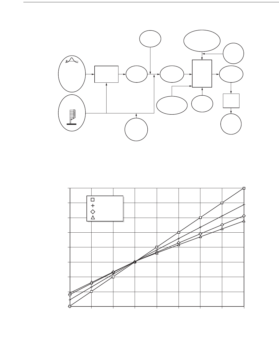
2.3.1.b Static Wave Analysis
The sequence of steps in the calculation of deterministic
static design wave forces on a fixed platform (neglecting plat-
form dynamic response and distortion of the incident wave by
the platform) is shown graphically in Figure 2.3.1-1. The pro-
cedure, for a given wave direction, begins with the specifica-
tion of the design wave height and associated wave period,
storm water depth, and current profile. Values of these param-
eters for U.S. waters are specified in 2.3.4. The wave force
calculation procedure follows these steps:
• An apparent wave period is determined, accounting for
the Doppler effect of the current on the wave.
• The two-dimensional wave kinematics are determined
from an appropriate wave theory for the specified wave
height, storm water depth, and apparent period.
• The horizontal components of wave-induced particle
velocities and accelerations are reduced by the wave
kinematics factor, which accounts primarily for wave
directional spreading.
• The effective local current profile is determined by
multiplying the specified current profile by the current
blockage factor.
• The effective local current profile is combined vectori-
ally with the wave kinematics to determine locally inci-
dent fluid velocities and accelerations for use in
Morison’s equation.
• Member dimensions are increased to account for
marine growth.
• Drag and inertia force coefficients are determined as
functions of wave and current parameters; and member
shape, roughness (marine growth), size, and orienta-
tion.
• Wave force coefficients for the conductor array are
reduced by the conductor shielding factor.
• Hydrodynamic models for risers and appurtenances are
developed.
• Local wave/current forces are calculated for all plat-
form members, conductors, risers, and appurtenances
using Morison’s equation.
• The global force is computed as the vector sum of all
the local forces.
The discussion in the remainder of this section is in the
same order as the steps listed above. There is also some dis-
cussion on local forces (such as slam and lift) that are not
included in the global force.
1. Apparent Wave Period. A current in the wave direction
tends to stretch the wave length, while an opposing current
shortens it. For the simple case of a wave propagating on a
uniform in-line current, the apparent wave period seen by an
observer moving with the current can be estimated from Fig-
ure 2.3.1-2, in which T is the actual wave period (as seen by a
stationary observer). V
I
is the current component in the wave
direction, d, is storm water depth (including storm surge and
tide), and g is the acceleration of gravity. This figure provides
estimates for d/gT
2
> 0.01. For smaller values of d/gT
2
, the
equation (T
app
/T) = 1 + V
I
can be used. While strictly
applicable only to a current that is uniform over the full water
depth, Figure 2.3.1-2 provides acceptable estimates of T
app
for “slab” current profiles that are uniform over the top 165 ft
(50m) or more of the water column. For other current pro-
files, a system of simultaneous nonlinear equations must be
solved interactively to determine T
app
(see Commentary).
The current used to determine T
app
should be the free-stream
current (not reduced by structure blockage).
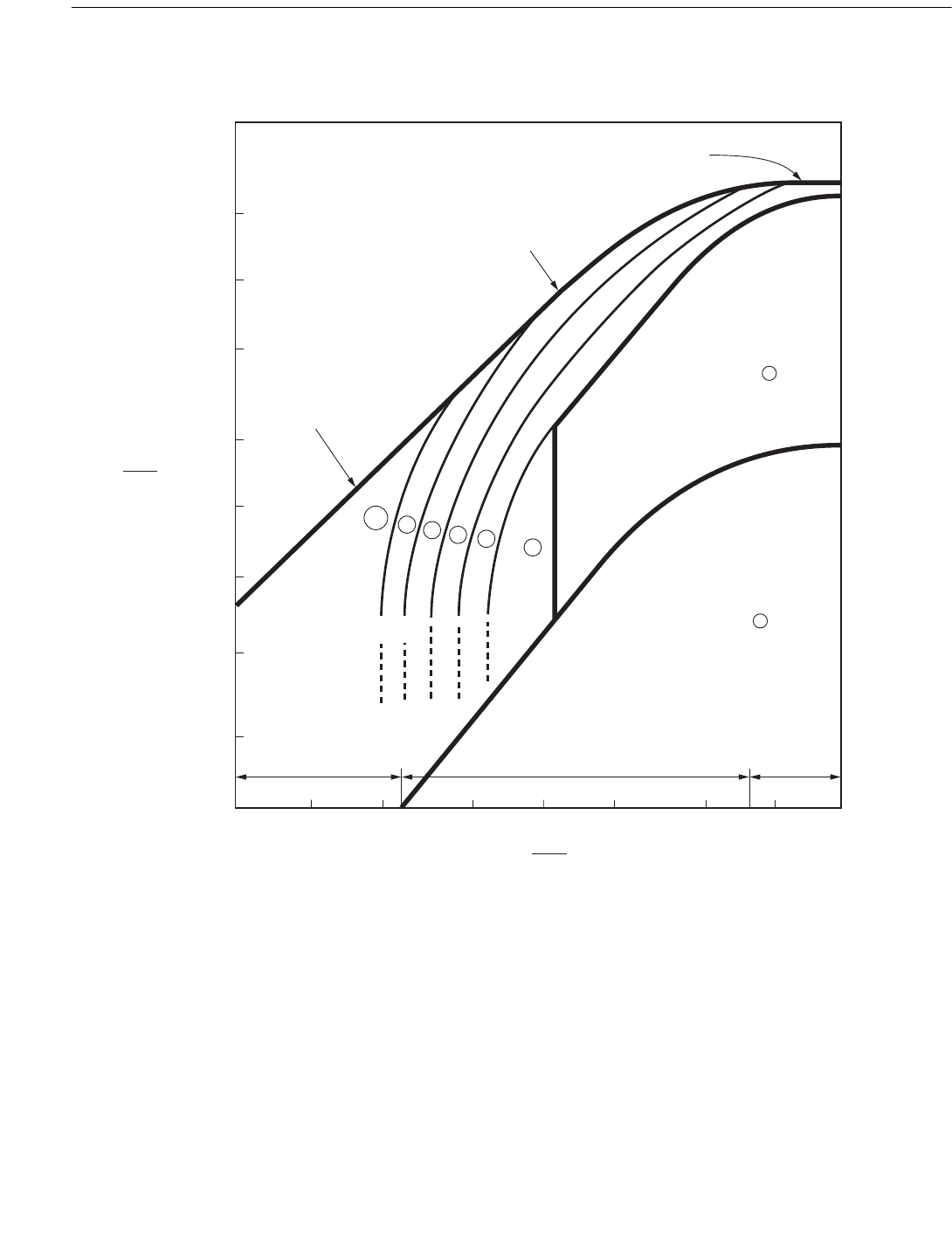
2. Two-Dimensional Wave Kinematics. For the apparent
wave period T
app
, specified wave height H, and storm water
depth, d, two-dimensional regular wave kinematics can be
calculated using the appropriate order of Stream Function
wave theory. In many cases, Stokes V wave theory will pro-
duce acceptable accuracy. Figure 2.3.1-3 Atkins (1990)
shows the regions of applicability of Stokes V and various
orders of Stream Function solutions in the H/gT
app
2
, d/gT
app
2
plane. Other wave theories, such as Extended Velocity Poten-
tial and Chappelear, may be used if an appropriate order of solution is selected.
gd
Copyright American Petroleum Institute
Provided by IHS under license with API
Licensee=Indonesia location/5940240008
Not for Resale, 10/22/2008 00:07:12 MDT
No reproduction or networking permitted without license from IHS
RECOMMENDED PRACTICE FOR PLANNING, DESIGNING AND CONSTRUCTING FIXED OFFSHORE PLATFORMS—WORKING STRESS DESIGN 13
Figure 2.3.1-1—Procedure for Calculation of Wave Plus Current Forces for Static Analysis
Figure 2.3.1-2—Doppler Shift Due to Steady Current
\U:DYH
+HLJKWDQG
$VVRFLDWHG
:DYH3HULRG
DQG
6WRUP:DWHU
'HSWK
$VVRFLDWHG
&XUUHQW
'
:DYH7KHRU\
,QFOXGLQJ
'RSSOHU(IIHFW
:DYH
.LQHPDWLFV
&XUUHQW
%ORFNDJH
)DFWRU
±
:DYH
.LQHPDWLFV
)DFWRU
:DYH3OXV
&XUUHQW
.LQHPDWLFV
5LVHUDQG
$SSXUWHQDQFH
+\GURG\QDPLF
0RGHOV
6PRRWK
5RXJK
&G
&P
/RFDO
0HPEHU
:DYH3OXV
&XUUHQW
)RUFHV
%DVHGRQ
0RULVRQ
(TXDWLRQ
0DULQH
*URZWK
&RQGXFWRU
6KLHOGLQJ
)DFWRU
'LVWULEXWHG
)RUFHV
9HFWRU
6XP
*OREDO
)RUFHV
± ± ±
9
,
J7
7DDS7
GJ7
Copyright American Petroleum Institute
Provided by IHS under license with API
Licensee=Indonesia location/5940240008
Not for Resale, 10/22/2008 00:07:12 MDT
--`,,```,,,`,,,,,,,,,,,,,,`,``,`-`-`,,`,,`,`,,`---
14 API RECOMMENDED PRACTICE 2A-WSD
Figure 2.3.1-3—Regions of Applicability of Stream Function, Stokes V, and Linear Wave Theory
(From Atkins, 1990; Modified by API Task Group on Wave Force Commentary)
+
J7
DSS
G
J7
DSS
6KDOORZ
:DWHU:DYHV
,QWHUPHGLDWH'HSWK:DYHV
'HHS
:DWHU
:DYHV
/LQHDU$LU\
RU6WUHDP)XQFWLRQ
6WRNHV
RU6WUHDP)XQFWLRQ
6WUHDP)XQFWLRQ
6KDOORZ:DWHU
%UHDNLQJ/LPLW
+G
'HHS:DWHU
%UHDNLQJ/LPLW
+/
+
E
!
+J7
DSS
GJ7
DSS
+
+
E
'LPHQVLRQOHVVZDYHVWHHSQHVV
'LPHQVLRQOHVVUHODWLYHGHSWK
:DYHKHLJKW
%UHDNLQJZDYHKHLJKW
G
7
DSS
J
0HDQZDWHUGHSWK
:DYHSHULRG
$FFHOHUDWLRQRIJUDYLW\
Copyright American Petroleum Institute
Provided by IHS under license with API
Licensee=Indonesia location/5940240008
Not for Resale, 10/22/2008 00:07:12 MDT
--`,,```,,,`,,,,,,,,,,,,,,`,``,`-`-`,,`,,`,`,,`---

RECOMMENDED PRACTICE FOR PLANNING, DESIGNING AND CONSTRUCTING FIXED OFFSHORE PLATFORMS—WORKING STRESS DESIGN 15
3. Wave Kinematics Factor. The two-dimensional regular
wave kinematics from Stream Function or Stokes V wave
theory do not account for wave directional spreading or irreg-
ularity in wave profile shape. These “real world” wave
characteristics can be approximately modeled in determinis-
tic wave analyses by multiplying the horizontal velocities and
accelerations from the two-dimensional regular wave solu-
tion by a wave kinematics factor. Wave kinematics
measurements support a factor in the range 0.85 to 0.95 for
tropical storms and 0.95 to 1.00 for extra-tropical storms. Par-
ticular values within these ranges that should be used for
calculating guideline wave forces are specified for the Gulf of
Mexico in 2.3.4d.1 and for other U.S. waters in 2.3.4f.1. The
Commentary provides additional guidance for calculating the
wave kinematics factor for particular sea states whose direc-
tional spreading characteristics are known from
measurements or hindcasts.
4. Current Blockage Factor. The current speed in the vicin-
ity of the platform is reduced from the specified “free stream”
value by blockage. In other words, the presence of the struc-
ture causes the incident flow to diverge; some of the incident
flow goes around the structure rather than through it, and the
current speed within the structure is reduced. Since global
platform loads are determined by summing local loads from
Morison’s equation, the appropriate local current speed
should be used.
Approximate current blockage factors for typical Gulf of
Mexico jacket-type structures are as follows:
For structures with other configurations or structures with
a typical number of conductors, a current blockage factor can
be calculated with the method described in the Commentary.
Calculated factors less than 0.7 should not be used without
empirical evidence to support them. For freestanding or
braced caissons the current blockage factor should be 1.0.
5. Combined Wave/Current Kinematics. Wave kinemat-
ics, adjusted for directional spreading and irregularity, should
be combined vectorially with the current profile, adjusted for
blockage. Since the current profile is specified only to storm
mean water level in the design criteria, some way to stretch
(or compress) it to the local wave surface must be used. As
discussed in the Commentary, “nonlinear stretching” is the
preferred method. For slab current profiles such as those
specified for U.S. waters in 2.3.4, simple vertical extension of
the current profile from storm mean wear level to the wave
surface is a good approximation to nonlinear stretching. For
other current profiles, linear stretching is an acceptable
approximation. In linear stretching, the current at a point with
elevation z, above which the wave surface elevation is
η
(where z and
η
are both positive above storm mean water
level and negative below), is computed from the specified
current profile at elevation z´ The elevations z and z´ are lin-
early related, as follows:
(z´ + d) = (z + d) d/(d +
η
)
where
d = storm water depth.
6. Marine Growth. All structural members, conductors, ris-
ers, and appurtenances should be increased in cross-sectional
area to account for marine growth thickness. Also, elements
with circular cross-sections should be classified as either
“smooth” or “rough” depending on the amount of marine
growth expected to have accumulated on them at the time of
the loading event. Specific marine growth profiles are pro-
vided for U.S. waters in 2.3.4.
7. Drag and Inertia Coefficients. Drag and inertia coeffi-
cients are discussed in detail in the Commentary. For typical
design situations, global platform wave forces can be calcu-
lated using the following values for unshielded circular
cylinders:
smooth C
d
= 0.65, C
m
= 1.6
rough C
d
= 1.05, C
m
= 1.2
These values are appropriate for the case of a steady cur-
rent with negligible waves or the case of large waves with
U
mo
T
app
/D > 30. Here, U
mo
is the maximum horizontal parti-
cle velocity at storm mean water level under the wave crest
from the two-dimensional wave kinematics theory, T
app
is the
apparent wave period, and D is platform leg diameter at storm
mean water level.
For wave-dominant cases with U
mo
T
app
/D < 30, guidance
on how C
d
and C
m
for nearly vertical members are modified
by “wake encounter” is provided in the Commentary. Such
situations may arise with large-diameter caissons in extreme
seas or ordinary platform members in lower sea states consid-
ered in fatigue analyses.
# of Legs Heading Factor
3all 0.90
4end-on 0.80
diagonal 0.85
broadside 0.80
6end-on 0.75
diagonal 0.85
broadside 0.80
8end-on 0.70
diagonal 0.85
broadside 0.80
Copyright American Petroleum Institute
Provided by IHS under license with API
Licensee=Indonesia location/5940240008
Not for Resale, 10/22/2008 00:07:12 MDT
--`,,```,,,`,,,,,,,,,,,,,,`,``,`-`-`,,`,,`,`,,`---
16 API RECOMMENDED PRACTICE 2A-WSD
For members that are not circular cylinders, appropriate
coefficients can be found in Det norske Veritas’ “Rules for
the Design, Construction, and Inspection of Offshore Struc-
tures; Appendix B—Loads,” 1977.
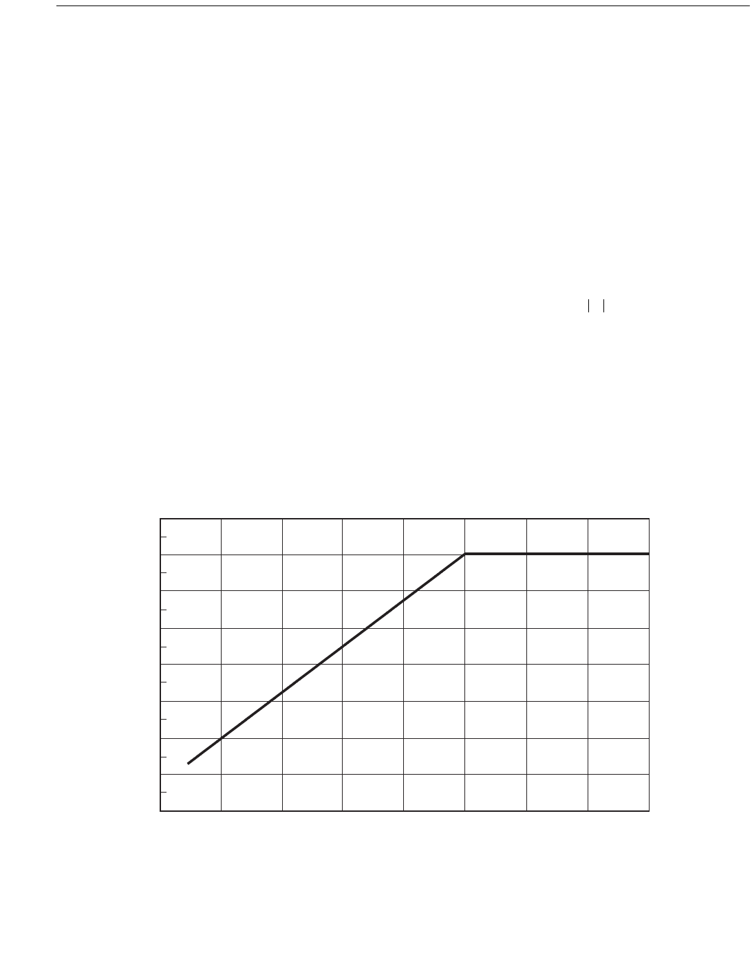
8. Conductor Shielding Factor. Depending upon the con-
figuration of the structure and the number of well conductors,
the wave forces on the conductors can be a significant portion
of the total wave forces. If the conductors are closely spaced,
the forces on them may be reduced due to hydrodynamic
shielding. A wave force reduction factor, to be applied to the
drag and inertia coefficients for the conductor array, can be
estimated from Figure 2.3.1-4, in which S is the center-to-
center spacing of the conductors in the wave direction and D
is the diameter of the conductors, including marine growth.
This shielding factor is appropriate for either (a) steady cur-
rent with negligible waves or (b) extreme waves, with U
mo
T
app
/S > 5π. For less extreme waves with U
mo
T
app
/S < 5π, as
in fatigue analyses, there may be less shielding. The Com-
mentary provides some guidance on conductor shielding
factors for fatigue analyses.
9. Hydrodynamic Models for Appurtenances. Appurte-
nances such as boat landings, fenders or bumpers, walkways,
stairways, grout lines, and anodes should be considered for
inclusion in the hydrodynamic model of the structure.
Depending upon the type and number of appurtenances, they
can significantly increase the global wave forces. In addition,
forces on some appurtenances may be important for local
member design. Appurtenances are generally modeled by
non-structural members which contribute equivalent wave
forces. For appurtenances such as boat landings, wave forces
are highly dependent on wave direction because of shielding
effects. Additional guidance on the modeling of appurte-
nances is provided in the Commentary.
10. Morison Equation. The computation of the force
exerted by waves on a cylindrical object depends on the ratio
of the wavelength to the member diameter. When this ratio is
large (> 5), the member does not significantly modify the
incident wave. The wave force can then be computed as the
sum of a drag force and an inertia force, as follows:
(2.3.1-1)
where
F = hydrodynamic force vector per unit length acting
normal to the axis of the member, lb/ft (N/m),
F
D
= drag force vector per unit length acting to the axis
of the member in the plane of the member axis
and U, lb/ft (N/m),
6'
6KLHOGLQJ)DFWRU
Figure 2.3.1-4—Shielding Factor for Wave Loads on Conductor
Arrays as a Function of Conductor Spacing
FF
D
F
I
+ C
D
w
2g
------ AUU C
m
w
g
---- V
δU
δt
-------+==
Copyright American Petroleum Institute
Provided by IHS under license with API
Licensee=Indonesia location/5940240008
Not for Resale, 10/22/2008 00:07:12 MDT
--`,,```,,,`,,,,,,,,,,,,,,`,``,`-`-`,,`,,`,`,,`---

RECOMMENDED PRACTICE FOR PLANNING, DESIGNING AND CONSTRUCTING FIXED OFFSHORE PLATFORMS—WORKING STRESS DESIGN 17
F
I
= inertia force vector per unit length acting normal
to the axis of the member in the plane of the
member axis and αU/αt, lb/ft (N/m),
C
d
= drag coefficient,
w = weight density of water, lb/ft
3
(N/m
3
),
g = gravitational acceleration, ft/sec
2
(m/sec
2
),
A = projected area normal to the cylinder axis per unit
length (= D for circular cylinders), ft (m),
V = displaced volume of the cylinder per unit length
(= πD
2
/4 for circular cylinders), ft
2
(m
2
),
D = effective diameter of circular cylindrical member
including marine growth, ft (m),
U = component of the velocity vector (due to wave
and/or current) of the water normal to the axis of
the member, ft/sec (m/sec),
|U| = absolute value of U, ft/sec (m/sec),
C
m
= inertia coefficient,
= component of the local acceleration vector of the
water normal to the axis of the member, ft/sec
2
(m/sec
2
).
Note that the Morison equation, as stated here, ignores the
convective acceleration component in the inertia force calcu-
lation (see Commentary). It also ignores lift forces, slam
forces, and axial Froude-Krylov forces.
When the size of a structural body or member is suffi-
ciently large to span a significant portion of a wavelength, the
incident waves are scattered, or diffracted. This diffraction
regime is usually considered to occur when the member
width exceeds a fifth of the incident wave length. Diffraction
theory, which computes the pressure acting on the structure
due to both the incident wave and the scattered wave, should
be used, instead of the Morison equation, to determine the
wave forces. Depending on their diameters, caissons may be
in the diffraction regime, particularly for the lower sea states
associated with fatigue conditions. Diffraction theory is
reviewed in “Mechanics of Wave Forces on Offshore Struc-
tures” by T. Sarpkaya and M. Isaacson, Van Nostrand Rein-
hold Co., 1981. A solution of the linear diffraction problem
for a vertical cylinder extending from the sea bottom through
the free surface (caisson) can be found in “Wave Forces on
Piles: A Diffraction Theory,” by R. C. MacCamy and R. A.
Fuchs, U.S. Army Corps of Engineers, Beach Erosion Board,
Tech. Memo No. 69, 1954.
11. Global Structure Forces. Total base shear and overturn-
ing moment are calculated by a vector summation of (a) local
drag and inertia forces due to waves and currents (see
2.3.1b20), (b) dynamic amplification of wave and current
forces (see 2.3.1c), and (c) wind forces on the exposed por-
tions of the structure (see 2.3.2). Slam forces can be neglected
because they are nearly vertical. Lift forces can be neglected
for jacket-type structures because they are not correlated from
member to member. Axial Froude-Krylov forces can also be
neglected. The wave crest should be positioned relative to the
structure so that the total base shear and overturning moment
have their maximum values. It should be kept in mind that:
(a) maximum base shear may not occur at the same wave
position as maximum overturning moment; (b) in special
cases of waves with low steepness and an opposing current,
maximum global structure force may occur near the wave
trough rather than near the wave crest; and (c) maximum
local member stresses may occur for a wave position other
than that causing the maximum global structure force.
12. Local Member Design. Local member stresses are due
to both local hydrodynamic forces and loads transferred from
the rest of the structure. Locally generated forces include not
only the drag and inertia forces modeled by Morison’s equa-
tion (Eq. 2.3.1-1), but also lift forces, axial Froude-Krylov
forces, and buoyancy and weight. Horizontal members near
storm mean water level will also experience vertical slam
forces as a wave passes. Both lift and slam forces can dynam-
ically excite individual members, thereby increasing stresses
(see Commentary). Transferred loads are due to the global
fluid-dynamic forces and dynamic response of the entire
structure. The fraction of total stress due to locally generated
forces is generally greater for members higher in the struc-
ture; therefore, local lift and slam forces may need to be
considered in designing these members. The maximum local
member stresses may occur at a different position of the wave
crest relative to the structure centerline than that which causes
the greatest global wave force on the platform. For example,
some members of conductor guide frames may experience
their greatest stresses due to vertical drag and inertia forces,
which generally peak when the wave crest is far away from
the structure centerline.
2.3.1.c Dynamic Wave Analysis
1. General. A dynamic analysis of a fixed platform is indi-
cated when the design sea state contains significant wave
energy at frequencies near the platform’s natural frequencies.
The wave energy content versus frequency can be described
by wave (energy) spectra as determined from measured data
or predictions appropriate for the platform site. Dynamic
analyses should be performed for guyed towers and tension
leg platforms.
2. Waves. Use of a random linear wave theory with modified
crest kinematics is appropriate for dynamic analysis of fixed
platforms. Wave spreading (three-dimensionality) should be
considered. Wave group effects may also cause important
dynamic responses in compliant structures.
δU
δt
-------
02
Copyright American Petroleum Institute
Provided by IHS under license with API
Licensee=Indonesia location/5940240008
Not for Resale, 10/22/2008 00:07:12 MDT
--`,,```,,,`,,,,,,,,,,,,,,`,``,`-`-`,,`,,`,`,,`---

18 API RECOMMENDED PRACTICE 2A-WSD
3. Currents. Currents associated with the design sea state
can affect dynamic loading through the nonlinear drag force
term in Morison’s Equation 2.3.1-1, and therefore should be
considered in dynamic analysis.
4. Winds. For analysis of template, tower, gravity, or mini-
mum platforms, global loads due to the sustained wind may
be superimposed on the global wave and current load.
For guyed towers and tension leg platforms, the analysis
should include the simultaneous action of wind, waves, and
current. It may be appropriate to consider wind dynamics.
5. Fluid Force on a Member. Equation 2.3.1-1 may be used
to compute forces on members of template, tower, gravity, or
minimum structure platforms. Guidance on selection of drag
and inertia coefficients for dynamic analysis is provided in
the Commentary on Wave Forces, C2.3.1b7. For guyed tow-
ers and tension leg platforms, Equation 2.3.1-1 should be
modified to account for relative velocity by making the fol-
lowing substitution in the drag force term:
replace U| U| by (U – )| U – |
where
= component of structural velocity normal to the
axis of the member, ft/sec (m/s),
U = as defined for Equation 2.3.1-1.
Fluid forces associated with the platform acceleration are
accounted for by added mass.
6. Structural Modeling. The dynamic model of fixed plat-
forms should reflect the key analytical parameters of mass,
damping, and stiffness. The mass should include that of the
platform steel, all appurtenances, conductors, and deck loads,
the mass of water enclosed in submerged tubular members,
the mass of marine growth expected to accumulate on the
structure and the added mass of submerged members,
accounting for increased member diameter due to marine
growth.
Equivalent viscous damping values may be used in lieu of
an explicit determination of damping components. In the
absence of substantiating information for damping values for
a specific structure, a damping value of two to three percent
of critical for extreme wave analyses and two percent of criti-
cal for fatigue analyses may be used.
The analytical model should include the elastic stiffness of
the platform and reflect the structure/foundation interaction.
It may be appropriate to consider a stiffer foundation for
fatigue analyses than for extreme wave response analyses.
For guyed towers, these stiffnesses should be augmented to
account for the guyline system. Analysis procedures may be
required that account for the dynamic interaction of the tower
and guyline system. Guyed tower analytical models should
include geometric stiffness (large displacement effects).
Forces affecting geometric stiffness include gravity loads,
buoyancy, the vertical component of the guyline system reac-
tion, and the weight of conductors including their contents.
7. Analysis Methods. Time history methods of dynamic
analysis are preferred for predicting the extreme wave
response of template platforms, minimum structures, and
guyed towers because these structures are generally drag
force dominated. The nonlinear system stiffness also indi-
cates time domain analysis for guyed towers. Frequency
domain methods may be used for extreme wave response
analysis to calculate the dynamic amplification factor to com-
bine with the static load, provided linearization of the drag
force can be justified; for guyed towers, both the drag force
and non-linear guyline stiffness would require linearization.
Frequency domain methods are generally appropriate for
small wave fatigue analysis.
For member design, stresses may be determined from
static analyses which include in an appropriate manner the
significant effects of dynamic response determined from
separate analyses made according to the provisions of this
Section.
2.3.2 Wind
2.3.2.a General
The wind criteria for design should be determined by
proper analysis of wind data collected in accordance with
1.3.2. As with wave loads, wind loads are dynamic in nature,
but some structures will respond to them in a nearly static
fashion. For conventional fixed steel templates in relatively
shallow water, winds are a minor contributor to global loads
(typically less than 10 percent). Sustained wind speeds should
be used to compute global platform wind loads, and gust
speeds should be used for the design of individual structural
elements.
In deeper water and for compliant designs, wind loads can
be significant and should be studied in detail. A dynamic
analysis of the platform is indicated when the wind field con-
tains energy at frequencies near the natural frequencies of the
platform. Such analyses may require knowledge of the wind
turbulence intensity, spectra, and spatial coherence. These
items are addressed below.
2.3.2.b Wind Properties
Wind speed and direction vary in space and time. On length
scales typical of even large offshore structures, statistical
wind properties (e.g., mean and standard deviation of speed)
taken over durations of the order of an hour do not vary hori-
zontally, but do change with elevation (profile factor). Within
long durations, there will be shorter durations with higher
mean speeds (gusts factor). Therefore, a wind speed value is
only meaningful if qualified by its elevation and duration.
x
·
x
·
x
·
00
00
02
00
Copyright American Petroleum Institute
Provided by IHS under license with API
Licensee=Indonesia location/5940240008
Not for Resale, 10/22/2008 00:07:12 MDT
No reproduction or networking permitted without license from IHS