ASM Metals HandBook Vol. 8 - Mechanical Testing and Evaluation
Подождите немного. Документ загружается.

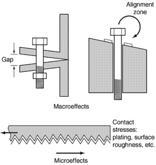
Fig. 28 Macroeffects and microeffects in the alignment zone
Zone 3: Elastic Clamping Range. In this zone, the slope of the torque-angle curve is essentially constant. The
elastic-clamping-zone torque-angle slope is a very important characteristic of each bolted joint. This slope can
be projected backward to zero torque to locate the elastic origin. For joints with prevailing torque in the
rundown zone, the elastic origin is located at the intersection of the prevailing torque level and the backward
projection of the tangent to the elastic clamping zone. If the angle of turn is measured from the elastic origin to
the point where torquing was stopped in the elastic clamping zone, the tension in the fastener is directly
proportional to that angle of turn. In this elastic zone, the compression of the parts and the stretching of the
fastener are occurring in a linear fashion from the projected elastic origin. Even if friction between threads or in
the underhead region of the fastener is varied, it still will be found that, within the elastic zone, the tension
generated is always proportional to the angle of turn from the elastic origin. The angle of turn from the elastic
origin to the point where the torque is removed can be multiplied by the angle-tension coefficient to estimate
the tension that has been created by the tightening process.
To further illustrate the concept of the elastic origin, the torque-angle signatures in Fig. 29 show the increased
slope, induced by increased friction, in the elastic tightening zone. It can be noted that as friction increases, the
torque required to bring the bolt to yield is also increased. The curves in Fig. 30 show that, as friction increases,
the clamp force at the yield point is reduced, while the torque that is required to reach the yield point increases.
This illustrates the fact that for a given fastener size, the torque required to yield the bolt is a function of the
material yield strength and the thread-friction coefficient.
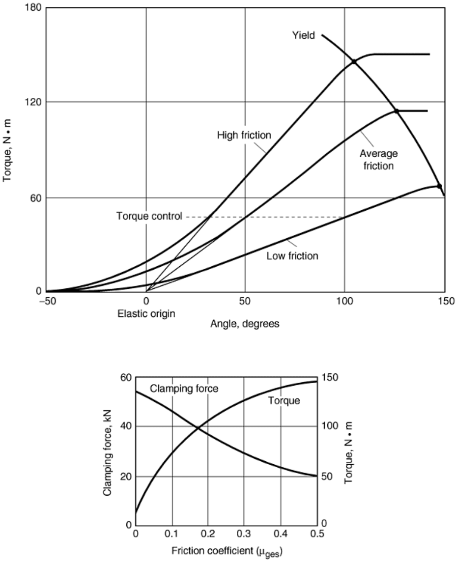
Fig. 29 Friction effects on yield point
Fig. 30 Friction effects on applied torque and clamping force at yield for class 9.8 M12 × 1.75 bolts
Zone 4: Post Yield. The post-yield zone begins with an inflection point at the end of the elastic clamping range.
Yielding can occur in the bolt or in the joint assembly as a result of underhead embedment or as thread strip in
the bolt or mating threads. This fourth zone can be due to yielding in the joint or gasket or due to yield of the
threads in the nut or clamped components or nut, rather than to yield of the fastener. The yield point of the bolt
can be used to approximate the angle-tension coefficient for the tightening process.
The yield clamp load of a torqued fastener is less than the tensile yield due to the combined tension and thread
torque. Because the thread friction coefficient is unknown, an initial assumption could be that the clamp load at
yield torque is about 90% of the tensile-yield load. This calculation would be approximately correct for an
average friction coefficient, μ
ges
, of 0.1.
Torque-Angle (M-Alpha) Diagram
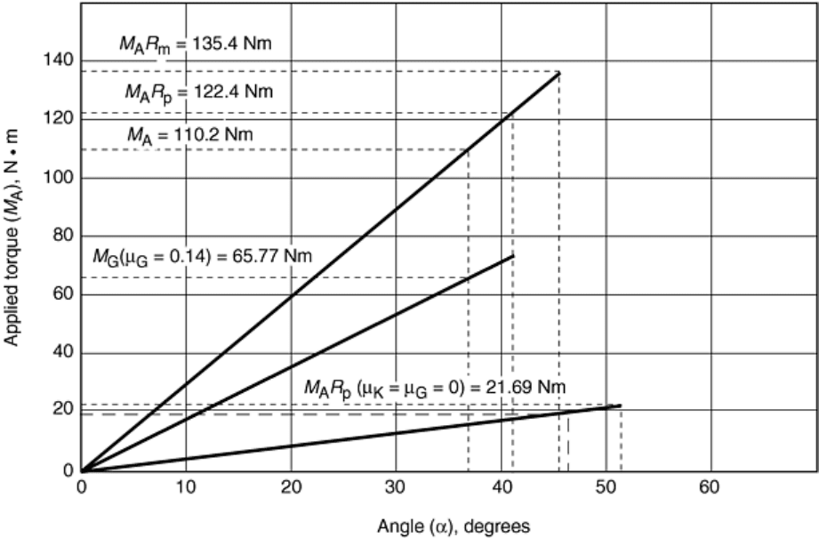
The torque-angle (M-alpha) diagram is a powerful tool for use in joint analysis. As shown in Fig. 31, it is a
straight-line projection of the tangent to the torque-angle assembly curve projected backward from the predicted
yield point through the elastic tightening point to zero torque. This tangent projection is used to locate the
elastic origin. Because the M-alpha diagrams in this discussion were developed using SR1, a bolted-joint stress
calculation software program based on the well-known German design standard, VDI 2230, terminology native
to VDI is used in this discussion, such as M for torque, from the German word Drehmoment (torque moment).
Fig. 31 Torque-angle diagram
In addition to the applied torque, M
A
, the torque-angle diagram has projections from the elastic origin for both
the thread torque, M
G
, and the pitch torque, M
G0
(where μ = 0). A very useful feature of the torque-angle
diagram is the manner in which the diagram clearly illustrates the distribution of the torque in a tightening
process. With M
A
showing the total input torque, M
G
represents the thread torque that is the thread friction plus
the pitch torque, which creates the clamp force. The difference between the M
A
and M
G
curves represents the
underhead-friction torque. The difference between the pitch torque curve, M
G0
, and the M
G
curve represents the
thread-friction torque.
The torque-angle diagram is a straight line projected from the elastic origin to the yield point. By changing the
coefficients for thread friction, μ
G
, and underhead friction, μ
K
, assumed for the VDI 2230 analysis, the effect of
friction on the tightening process can be clearly seen. In the diagram shown in Fig. 32, the torque values
required to reach the assembly preload and the yield point are lower because the assumed friction coefficients
are lower.
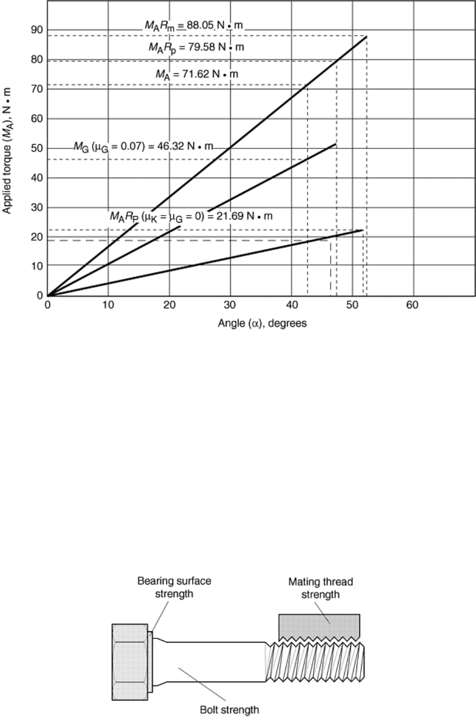
Fig. 32 Torque-angle diagram with low friction coefficients
Strength Considerations
The clamp force and preload requirements for a bolted joint are determined by the static and dynamic loads that
the assembly is expected to see in service. The bolted-joint design must be completely engineered with regard
to the axial (concentric), eccentric, and shear loads to which the assembly will be subjected. This design is the
first step in any fastener-engineering project.
After the external working loads have been defined, the necessary bolt preload can be calculated. Next, the
safety factors against embedment and thread strip must be checked to ensure that yielding in the bearing areas
or threads will not limit the preload to less than the required amount. Safety factors for shear slip, fatigue, loss
of preload, and overelongation due to combined loads must also be evaluated.
The safety factors for embedment and thread strip are important both for the initial installation of the fastener
and for long-term reliability with regard to both loosening and fatigue resistance. The illustration in Fig. 33
shows some of the strength factors that should be evaluated with regard to expected service loads and preload
requirements.
Fig. 33 Basic clamping force and material strength considerations
Bolt Yield
Tightening a fastener beyond the yield point is a means of achieving the maximum preload possible for a given
size and strength. This tightening method is commonly used in automotive engine assembly for connecting rod
bolts, crankshaft bearing cap bolts, and engine head bolts. When bolts first replaced rivets in the construction of
bridges and buildings, tightening beyond the yield point quickly proved to be a reliable method of assembly.
The preload obtained by tightening beyond the yield point is proportional to the material yield strength and
inversely proportional to the thread friction coefficient, μ
G
. The thread friction coefficient is important because
the yield point during tightening results from combined tensile loads plus the torsional load due to the thread
friction and pitch torque.
After the yield load is reached, the clamping force will continue to increase in proportion to the increase in
torque. In the elastic tightening zone, tension is proportional to the angle of turn from the elastic origin located
on the torque-angle signature. When tightening beyond the yield point, the clamping force can be estimated by
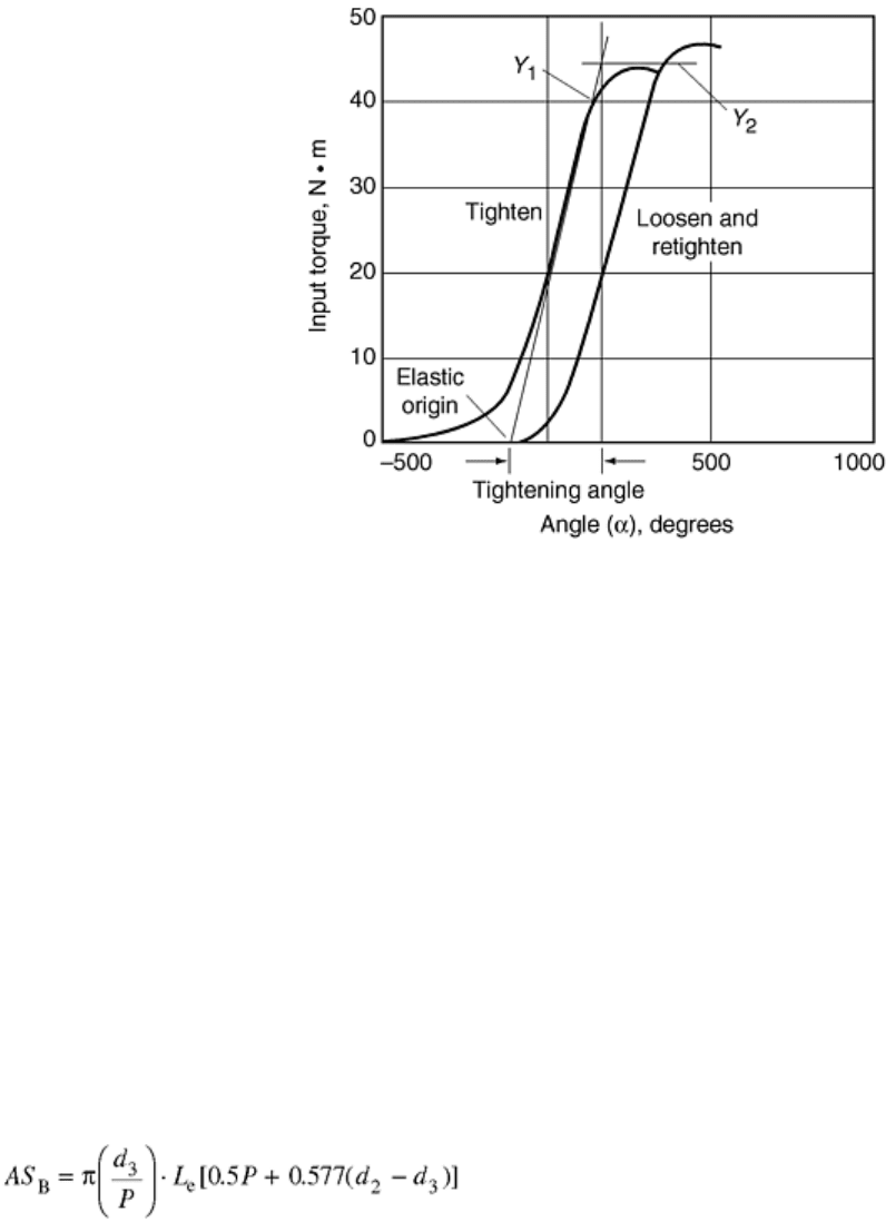
the procedure illustrated in Fig. 34.
Fig. 34 Bolt yield from initial tightening (Y
1
) and from loosening and retightening (Y
2
)
The tangent line to the elastic straight-line tightening section of the signature is projected beyond the yield
point, and the final torque value is projected to the tangent line. The angle of turn from the elastic origin to the
intercept of the backward projection from the final torque can be used to estimate the tension. This procedure
can be seen as related to the strain-hardening phenomena observed when working materials beyond the yield
point.
After the material is first loaded beyond yield, Y
1
, the yield point is found to be at a higher level, Y
2
, on the next
tightening cycle. After yielding, when the load is released, the release curve is offset and parallel to the elastic
tightening curve.
Thread Strip
In general, a properly designed bolted joint will not fail by stripping of the threads either during installation or
if the assembly is overloaded in tension. As a matter of good design practice, failure should always be due to
fracture of the bolt.
The thread-stripping areas for internal and external threads can be approximately calculated using the formulas
expressed in Eq 20 and 21. The geometric configurations that define the formulas are shown in Fig. 35.
(Eq 20)
where AS
B
is the shear area of the bolt; L
e
is the effective thread engagement; d
2
is the pitch diameter, external
thread; d
3
is the minor diameter, internal thread; and D
3
is the maximum diameter, internal thread.
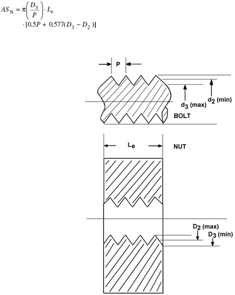
(Eq 21)
where AS
N
is the shear area of the nut thread; L
e
is the effective thread engagement (grip length of the fastener);
D
2
is the maximum pitch diameter, internal thread; D
3
is the major diameter, external thread; and d
3
is the
minimum diameter, external thread.
Fig. 35 Thread-stripping areas in bolted assemblies. P, pitch; L
e
, effective grip length of the fastener; d
2
,
bolt pitch diameter; d
3
, bolt root diameter; D
2
, nut pitch diameter; D
3
, nut root diameter
Assuming that the maximum shear strength of the bolt material equals half of the tensile strength (ductile
material, maximum shear stress failure mode), the bolt load to strip the threads can be estimated by multiplying
the calculated shear area times the shear strength of the bolt or nut. This formula is a simplified calculation that
assumes the loading is uniformly distributed on all engaged threads. In actual practice, due to the elastic
coupling between threads, the first engaged thread carries a higher-than-average load, while remaining threads
carry progressively lower loads as the load is transferred between the bolt and nut, or internally threaded hole.
When evaluating a bolted-joint, torque-angle assembly signature, the onset of thread stripping appears as a
yield point, or a change of slope in the elastic portion of the tightening curve (Fig. 36). The thread-strip
signature is similar to the signature for embedment of the fastener into the bearing surface. Both embedment
(described in the following section) and thread strip lead to creep of materials within the loaded surface areas of
the assembly. Over a period of time, embedment and excessive thread-stripping loads cause loss of preload as
the high-stress regions relax and redistribute the loads.
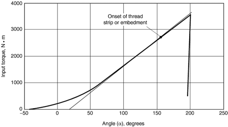
Fig. 36 Test plot of fastener with stripped threads
In service, thread-strip failure can be progressive in nature, gradually transferring the load from thread to
thread. Loss of preload due to thread strip can occur over many hours or days and is a cause of fastener
loosening that is often difficult to diagnose.
Embedment or Loss of Preload
The release-angle method has been successfully used to study fastener-loosening problems. The basic
procedure involves recording and analysis of the torque-angle signatures for tightening and then loosening the
fasteners that are to be tested.
First, the torque-angle-tightening curve is plotted, the elastic origin is located, and the amount of angle of turn
from the elastic origin is determined. After the assembly has been allowed to relax, for example, to sit overnight
or run on a dynamic field test, the fastener is loosened and the loosening curve is analyzed. The release angle is
determined, compared to the tightening angle, and if not equal, evaluated to see how much tension was lost by
relaxation or loosening.
In one release-angle study, a fastener had a tightening angle of 120°. After 10 to 12 h, the release angle was
20°. The manufacturer was already aware there was a major problem because the parts were literally falling
apart somewhere between the assembly factory and the automotive plant where they were delivered for final
assembly in vehicles. The signature-analysis study showed that creep or relaxation in the threads was causing
an approximately 80% loss in clamp force over a 12 h period. The release-angle method provided a quantitative
answer as to the amount of clamp force lost and clearly showed that the parts needed to be redesigned.
The release angle method is particularly valuable for studying short-grip-length fasteners holding composite or
plastic parts. These parts are generally too small to allow for use of strain gages or ultrasonic stretch
measurements to confirm fastener preload.
For these applications, a torque-angle signature curve for tightening is recorded, and the parts are then put in an
environmental chamber and load/temperature cycled.
Following the test-load cycle, the release-angle signature is recorded. Analysis of the release-angle signature in
comparison to the tightening signature is used to directly estimate the percentage of initial clamp load lost due
to embedment or creep of the plastic part in response to applied loads or temperature cycles. By changing
geometric shapes and washer size, the effects can be quantitatively measured and compared. The section
“Torque-Angle Tension Audits” describes an audit method that can be used along with the release-angle
method to help audit relatively fastener tension values.
Estimating the Angle-Tension Coefficient
A number of different methods can be used to determine the angle-tension coefficient for the bolted joint. A
basic assumption is that as the fastener is turned to develop preload in the joint, the fastener stretches, and the
clamped parts compress elastically according to the effective spring rates of the fastener and the clamped parts.
After the angle-tension coefficient is determined for elastic clamping through analysis of the torque-angle
signature, it is relatively easy to estimate the tension achieved when tightening beyond the bolt-yield point.
The angle-tension coefficient for each bolted joint must be determined in order to establish the control
parameters for torque-angle-tension control. By shutting off the assembly tool at a specified angle of turn after
the threshold torque is attained, the scatter in achieved tension will be much less than the scatter observed for
the same fasteners tightened with torque-only control. For this process to work reliably, it is necessary that the
threshold torque level for starting angle counting be set at a level above the alignment zone of the tightening
process.
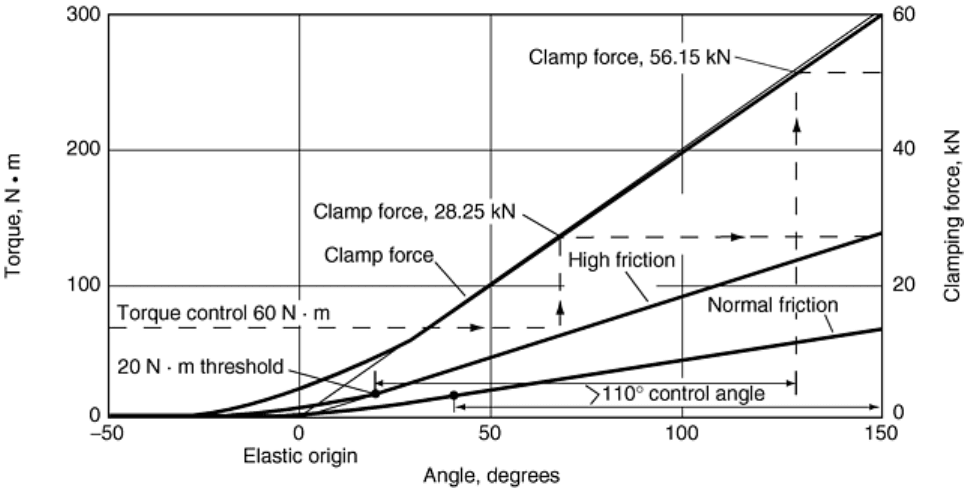
The curves in Fig. 37 show how the process control limits are determined to achieve torque-turn-tension control
for an application. Three examples are shown:
• With torque-angle control (110°) under normal friction, the clamping tension force achieved is 60 kN.
• With torque control of 60 N · m under high friction, the clamping tension achieved is 28.25 kN.
• With an angle count threshold of about 20 N · m and 110° torque-angle control, the clamping tension
achieved is 56.15 kN.
Fig. 37 Torque-turn-tension control principles. Three examples are shown; see text for discussion.
After the installation process has been defined and implemented, methods must be specified to audit the results
in order to verify that the process has achieved the desired fastener preload. Process audit procedures, including
the release-angle measurement method and hand-torque breakaway audits, are presented later.
Release Angle Analysis
The complete analysis of a fastener involves looking at both the tightening and the loosening torque-angle
curves as the fastener is first installed and then loosened. These curves are studied initially in the elastic
tightening region where the fastener has not gone beyond yield, such as the assembly torque-angle signature
shown in Fig. 38. When the fastener is loosened, a torque-angle-loosening signature, as shown in Fig. 39, can
be recorded. The release signature shows the release of the fastener stretch as well as the release of the
compression in the clamped parts. Analysis of this signature provides a direct method for verification of preload
or tightness. First, the line tangent to the elastic-release portion of the curve is projected to zero torque to locate
the elastic origin. The release angle, measured from the point where loosening starts to the projected elastic
origin, is a direct measure of the tension released from the bolted joint.
Fig. 38 Torque-angle assembly signature
Fig. 39 Torque-angle loosening signature
The tangent line must be drawn on the straight-line portion of the curve after the initial peak release torque due
to static friction or thread-locking adhesive that has been broken free. The starting point is the angle where
initial loosening motion begins. The total release angle is measured from the initial loosening point to the
projected elastic origin. Note that if a significant prevailing torque is present after loosening the fastener, the
elastic origin must be located at the prevailing level, not zero torque.
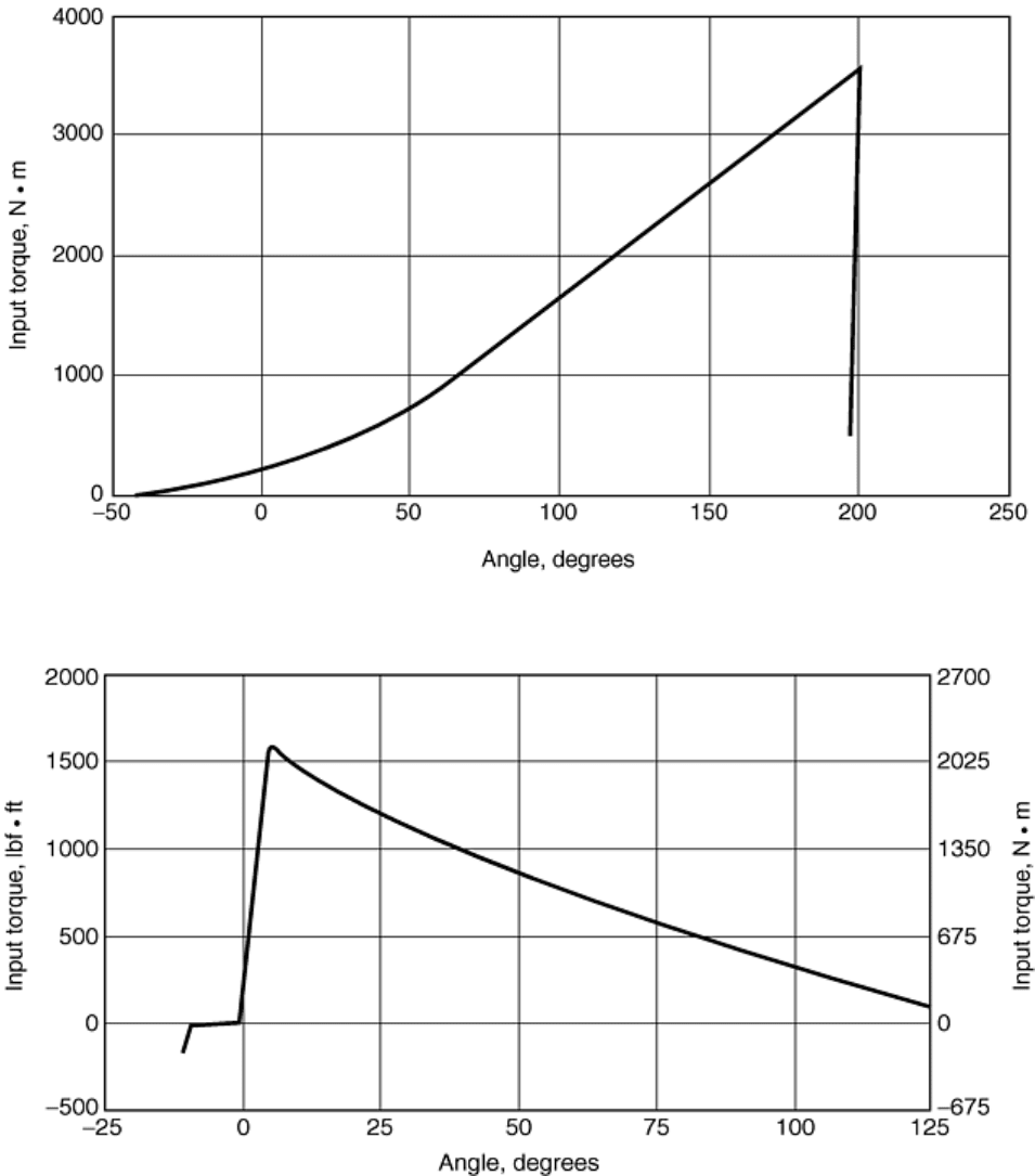
The torque-angle signature shown in Fig. 40 has been plotted as an M-alpha diagram with the tangent line,
locating the elastic origin, drawn at 50% of the maximum torque to set the elastic tightening slope below the
onset of embedment of the nut. The bolt is an M30 × 3.5 with a strength of class 11.9. The corresponding clamp
force signature, plotted as an F-alpha (tension-angle) diagram confirms that the clamp force increases linearly
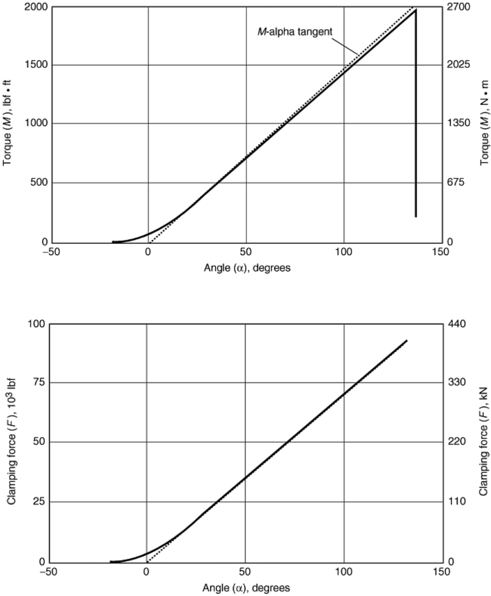
with the angle of turn from the projected elastic origin. In the example shown in Fig. 41, the elastic-tightening
angle is approximately 125°.
Fig. 40 Torque-angle signature showing embedment
Fig. 41 Clamp force vs. angle of turn from elastic origin
The loosening torque-angle signature (Fig. 39) also has a projected release angle of approximately 125°. The
tension-angle diagram (Fig. 41) confirms the fact that, even after embedment occurs, the clamp force increases
in direct proportion to the angle of turn from the elastic origin. Similar to the analysis of added tension achieved
after yield of the bolt, for embedment or thread strip, the backward projection to the extended tangent to the
curve before thread strip or embedment is used to locate the effective tightening angle. Experiments with strain-