ASM Metals HandBook Vol. 8 - Mechanical Testing and Evaluation
Подождите немного. Документ загружается.

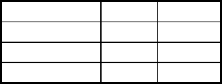
Wyoming-modified IITRI Smaller, more simply fabricated version of standard IITRI
fixture.
2
End-loaded specimen test methods
ASTM D 695 Designed for unreinforced plastics. Not very suitable for
composites.
3
Modified ASTM D 695 Currently a Boeing and SACMA recommended method.
Deviates extensively from the ASTM standard. Short (4.8
mm) gage length
2
Wyoming end-loaded, side
supported
Very simple fixture. Standard gage length. Limited by end
crushing to low and medium-strength materials unless end
tabs are used
2
RAE (Royal Aircraft
Establishment)
Thickness-tapered specimen. Simple fixture. Few detailed
results available
2
Block compression Limited by end crushing to low-strength composites unless
end reinforcement is used
3
Sandwich beam specimen test methods
ASTM D 3410 Method C-flexure Large specimen. Expensive to fabricate. Simple fixture.
Reliable results if specimen is properly designed to prevent
core failure
3
Sandwich column, axial loading Must fabricate sandwich laminate. End crushing a problem 3
Mini-sandwich column, axial
loading
Newly developed. Few data available. Promise of high
measured strengths
2
(a) As rated in Ref 10; see text for general description of rating criteria.
Source: Ref 10
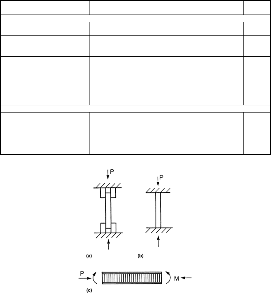
Fig. 9 Generic types of compression test methods. (a) Shear loaded. (b) End-loaded. (c) Sandwich beam
specimen.
IITRI Compression Test Method. Figure 10 is a schematic of the IITRI test fixture (ASTM Standard D 3410)
(see also Ref 10 and 21). The upper block of the fixture is bolted to the crosshead of the testing machine. The
lower block rests on the base of the test machine. The wedge grips have flat surfaces that rest in the end block
cavities. Large diameter (19 mm, or 0.75 in.) rods and linear bearings are used to maintain alignment during
linear motion of the upper block during testing. The standard IITRI test specimen is 140 mm (5.5 in.) long and
has a width dependent on the design of the wedge grips. The maximum width reported is 38.1 mm (1.5 in.) (Ref
10). Figure 11 shows the specimen geometry and dimensions for unidirectional composites. For laminates and
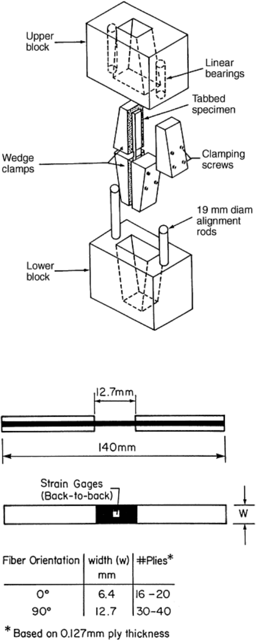
short-fiber composites, 25 mm (1 in.) wide specimens are recommended (Ref 9). Variations in specimen width
and thickness should be within ±0.03 mm (±0.001 in.). Untapered tabs are specified (Ref 20). Thickness,
materials, and bonding procedures for the end tabs are the same as for the tension test. Extreme care should be
taken to achieve tab surfaces parallel within 0.08 mm (0.003 in.).
Fig. 10 Compression test fixture developed at the Illinois Institute of Technology Research Institute
(IITRI). Source: Ref 10
Fig. 11 Dimensions for unidirectional specimens for the IITRI compression test
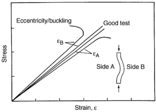
As with any compression test, concern about specimen buckling exists, and back-to-back strain gages should be
attached to the specimen surfaces in the gage region (Fig. 11). By monitoring the stress-strain response for each
gage, loading eccentricity and buckling instability can be detected. For a well-aligned, precisely machined
specimen, the strains from both surfaces will be in close agreement (Fig. 12). Bending caused by loading
eccentricity will cause the strains to diverge with increasing load until instability causes strain reversal (Fig.
12). When buckling instability occurs, the gage on the convex side will be relieved of some of its compressive
stress and the corresponding magnitude of strain will decrease. The gage on the concave side (A in Fig. 12) will
correspondingly experience an increased compressive strain. As a result of buckling, the apparent strength is
decreased, and the compression test is invalidated.
Fig. 12 Schematic of stress-strain responses for well aligned (good test) and eccentrically loaded (bad
test) compression test specimens
Since the compressive load is introduced in the specimen through shear (Fig. 9a) via tabs, there are stress
concentrations in the regions at the ends of the end tabs at the beginning of the gage section. Consequently,
failures are commonly observed close to the ends of the end tabs, but, as mentioned previously, such failures
are difficult to avoid and are commonly accepted.
Test Procedure. Measure the width and thickness of the specimen to within 0.03 mm (0.001 in.) at several
locations, and calculate the cross-sectional area. Attach strain gages on both sides of the specimen. Mount the
specimen in the grips and place the grips in the fixture, which should be placed between the crosshead and the
base on the centerline of the test machine. Set the crosshead speed at 0.59 to 1.2 mm/min (0.02 to 0.05 in./min).
The strain readings may be recorded continuously or at discrete load intervals. If discrete data are taken, the
strain readings should be captured at small load intervals in order to get at least 25 points in the linear response
region. A total of 40 to 50 points is desirable to establish the total stress-strain response. Monitor all specimens
to failure. Plot the data for reduction and inspect the stress-strain curves for signs of global bending of the
specimen. To obtain the ultimate strain, the response curve may need to be extrapolated, assuming linear elastic
behavior or curve fitting to the available stress-strain data. The modulus should be established by a least squares
fit of the initial slope and, once established, the procedure should be consistently employed for modulus
calculation.
Wyoming Modified Celanese Compression Test Method. The Wyoming-modified Celanese fixture is shown in
Fig. 13. This fixture was developed at the University of Wyoming and avoids several shortcomings of the
original Celanese fixture (ASTM standard D 3410). The fixture has wedge grips with a constant radius and does
not require the troublesome alignment sleeve of the Celanese fixture (see Ref 10, 22). The fixture is much
smaller than the IITRI fixture and weighs only about 4.5 kg, (10 lb), compared to about 40 kg (88 lb) for the
IITRI. The low weight provides for easier handling and requires less time for reaching thermal equilibrium in
nonambient temperature testing. The grips can, like the IITRI fixture (Fig. 10), be pretightened onto the test
specimen and allow alignment of each pair of wedges with respect to each other.
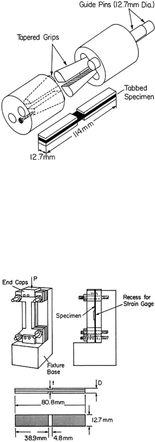
Fig. 13 Wyoming-modified Celanese compression test fixture. Source: Ref 10
The test specimen is 114 mm (4.5 in.) long and 12.7 mm (0.5 in.) wide. The gage length is 12.7 mm (0.5 in.).
The fixture can accommodate specimens that are between 3.8 and 6.4 mm (0.15 and 0.25 in.) thick in the tab
region. Specimen fabrication, bonding of end tabs, tolerances, and testing and failure modes are equivalent to
those outlined for the IITRI test.
Boeing Modified ASTM D 695 Test. The ASTM D 695 method as modified by Boeing (Ref 23) is illustrated in
Fig. 14. The test method was adopted by SACMA as a recommended test method (SRM 1-88, April 1989) and
is also under consideration for adoption by ASTM. As shown in Fig. 14, the specimen is end-loaded and face-
supported with a 0° orientation; the test is predominantly used to measure longitudinal properties. To obtain
both modulus and strength data, two tests are required. For strength measurement, tabs are bonded onto the
specimen, increasing the bearing area in the end-loaded regions. For modulus determination, the specimen is
not tested to failure, and the tabs are omitted.
Material t, mm
D, mm
0° Uni tape 1.00 3.00
90° Uni tape
2.50 7.50
Fabric 2.50 7.50
Fig. 14 Boeing-modified ASTM D 695 compression test fixture. Source: Ref 10
The standard specimen is 80.8 mm (3.2 in.) long and 12.7 mm (0.5 in.) wide. Specimen thickness
recommendations are given in the table in Fig. 14. A thin, tabbed specimen subjected to compression is face-
supported along its length, except for the 4.8 mm (0.19 in.) long gage section, and buckling is commonly not a
problem. For compressive strength determination, two continuous lateral supports without the strain gage recess
are used. Typically, untapered [0/90°] or plain-weave fabric tabs made from the same type of material as that
being tested are used. To determine the modulus, a strain gage is bonded at the center of an untabbed specimen,
and a lateral support with a central cutout to provide clearance for the strain gage and its connections is used.
As an alternative, continuous supports may be used with an extensometer attached to the specimen edge. The
specimen should be deformed at least to 0.3% (Ref 10).
The end-load introduction can cause axial splitting or bearing failures on the loaded ends. This must be
prevented and has prompted the use of tabs and end caps. Another problem is alignment. Alignment depends on
the machining precision of the specimen ends; that is, on the parallelism between opposing ends and the
perpendicularity of these ends to the specimen loading axis. Not only must the specimen be precise, but the test
machine platens must also be precisely parallel and aligned with the axis of the test machine. Tolerances for
specimen thickness and thickness of the tabbed region (t and D in Fig. 14) are ±0.1 mm (±0.004 in.). Tabs must
be flat, parallel, and of equal thickness to within 0.05 mm (0.002 in.). Ends must be surface ground flat to
within 0.03 mm (0.001 in.) and perpendicular to the reference axis. The third source of alignment error is
specimen insertion. Much of the fixture-design complexity revolves around the preservation of specimen
alignment in the test machine.
Because of the end loading, severe stress concentrations exist at the loaded ends. For the untabbed specimens
used to measure modulus, this is not considered a problem because the central region is far away from the
loaded edges. For the tabbed strength specimen, the use of tabs prevents failure at the loaded ends. For valid
strength tests, failure modes and strength values similar to those seen with other compression test methods have
been observed (Ref 10). Specimen fabrication, bonding of end tabs, and testing are equivalent to those specified
for the IITRI test.
A number of studies have been conducted exploring the use of [0/90°] laminate configurations to obtain better
strength results (Ref 24, 25). Results have shown that the highest strengths and lowest variability are measured
using [90/0
2
/90°]s laminates. Work by Welsh and Adams (Ref 26) confirmed the benefit of using [90/0°]
laminate subgroupings to achieve higher strengths for either IITRI or modified ASTM D 695 test
configurations. This is one area where serious consideration is being given to develop a standard based on
laminate tests for determination of lamina properties.
Extending this concept, Adams and Welsh (Ref 27) have developed a new test method that uses combined
loading to measure compression strength. The method uses both shear and end loading to test the [90/0°]
laminate specimen and has been shown to produce results that are consistent with properly conducted tests
using existing ASTM methods. An advantage of the method is the ease of testing and very consistent (low
scatter) results. The method is currently under review for ASTM standardization.
Flexure Testing
Flexure, or bending, tests have emerged because of the simplicity of specimen preparation and testing. Figure
15 shows stresses developed in the three-point flexure test. It is readily observed that gripping, buckling, and
end-tabbing are not issues for this test and that testing is very simple. Analysis of the test reveals that the
bending moment is balanced by a distribution of normal stress, σ
x
. The top side is under compression while the
bottom surface is under tension. Theoretically, the neutral axis is identically at the midplane where the shear
stress, τ
xy
, is maximum (see, e.g., Ref 28). In practice, differences in the tension and compression moduli
exhibited by many composites invalidate this assumption, moving the neutral axis off the midplane of the beam
and, unless corrected, making standard data reduction calculations erroneous. Depending on the span-to-
thickness ratio (L/h) and the strengths in tension, compression, and shear, the beam may fail in tension,
compression, or shear. It can be shown that shear failure occurs at very short spans, and that failure in tension
and compression occurs for longer spans. The three-point bend test for interlaminar shear strength
determination is discussed in the section “Shear Testing” in this article. In this section it is assumed that the
beam span is long enough to promote failure in tension or compression. Flexure tests are not recommended for
determination of design data because deformation and failure of the material occurs under a combined stress
state, and stress concentrations at load introduction points and supports may trigger failure (Ref 29).
Consequently, the flexural modulus and strength are combinations of the corresponding tensile and compressive
properties of the material. The flexure tests, however, may be used as a reference to previously obtained tensile
and compressive data.
Fig. 15 Illustration of bending and shear stresses in the three-point flexure test
The flexure test is generally limited to unidirectional materials with the fibers aligned parallel or perpendicular
to the beam axis. For laminates, interpretation of the results requires laminated beam theory (Ref 30).
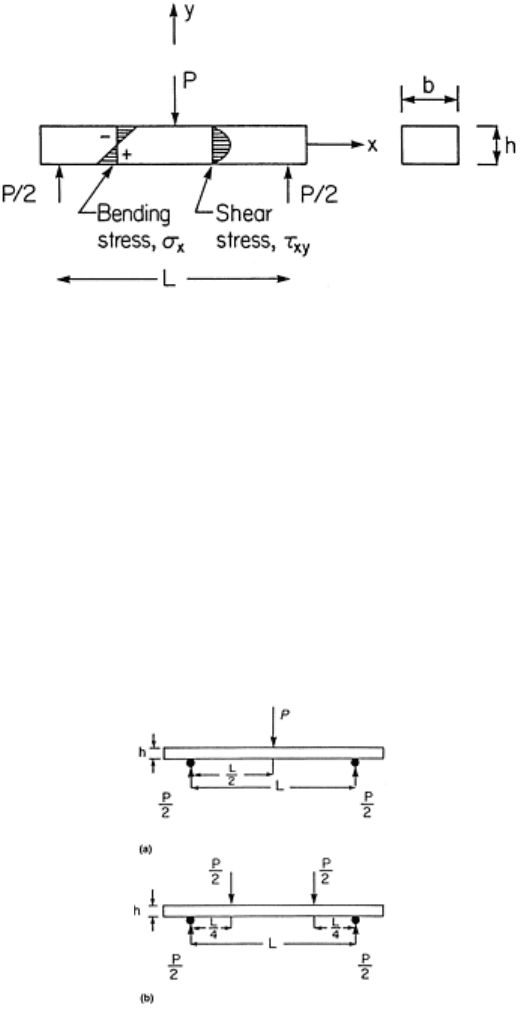
Flexure Test Methods. Flexure testing utilizes the three-point or four-point methods (Fig. 16). The four-point
flexure test is commonly performed with load noses located at the quarter-span points (Fig. 16b) but is
sometimes configured with the loading at the third span (L/3) locations. Flexure tests are most commonly used
to generate flexural modulus and strength for the purpose of quality control. Proper testing and data reduction
may render the test data of more value than just a quality check. The span-to-thickness ratio, L/h, should be
large for materials with a large ratio between the tensile and interlaminar shear strengths. For glass/epoxy tested
along the fiber direction and graphite/epoxy tested perpendicular to the fiber direction, L/h = 16 is appropriate.
For high tensile strength composites such as graphite/epoxy tested along the fiber direction, L/h = 32 is
recommended (Ref 4). The diameter of the load noses and support pins should, according to ASTM standard D
790, be at least 6.4 mm (0.25 in.). The maximum diameter is three times the specimen thickness.
Fig. 16 Schematic of flexure tests. (a) Three-point loading. (b) Four-point loading
Specimen Preparation and Flexure Testing. The specimen is nominally 130 mm (5.1 in.) long, although longer
span lengths would require longer specimens (see ASTM standard D 790). Although the ASTM standard D 790
does not indicate tolerances for the width, the ASTM D 3039 standard for tension testing specifies variations
within ±1%, which would amount to ±0.13 mm (±0.005 in.) for the flexure specimen. The accuracy of the total
length is less critical. Typically, 0° specimens use 12 to 16 plies, and 90° specimens use 16 to 30 plies (0.127
mm or 0.005 in., ply thickness).
Measure the cross-sectional dimensions of the test specimens to obtain an average of six measurements and
check for parallelism of the edges. If a strain gage is to be used, bond one longitudinal strain gage at the
geometrical center on the intended tension side of the specimen. The flexure fixture should be mounted in a
properly aligned and calibrated test fixture. Determine the support span according to the beam thickness and
material specifications as discussed previously, and set the support and load spans within 1% of their desired
values. The crosshead rate, , should be selected so that the maximum strain rate (for a surface fiber) is =
0.01/min. For both the three-point and four-point methods (at quarter points), this leads to (Ref 4):
= L
2
/6h
(Eq 1)
Commonly, a crosshead rate in the range 1 to 5 mm/min (0.05 to 0.2 in./min) is selected. For three-point
loading, place the specimen in the fixture with the strain gage on the tension side centered directly under the
central loading pin. For four-point loading, the strain gage may be on either the top (compression) or bottom
(tension) surface. If the vertical beam deflection, δ, is measured, place a calibrated linear voltage differential
transformer (LVDT) or extensometer at the beam midspan. The vertical displacement may be approximated as
the crosshead travel if the additional displacement due to the machine compliance is subtracted. The strain or
displacement readings may be recorded continuously or at discrete load intervals. If discrete data are recorded,
take the load and strain/displacement readings at small load intervals with at least 25 points in the linear
response region. A total of at least 40 points is desirable for description of the response up to failure.
Data Reduction for Three-Point Loading. The flexural stress at the specimen surface at beam midspan is
calculated from:
σ = 3PL/2bh
2
(Eq 2)
where P is the applied load, L is the span, b is the specimen width, and h is the specimen thickness.
If specimens with greater than a 16 to 1 span-to-thickness ratio are used, a correction factor must be used to
compensate for the geometric nonlinearity caused by the large deflections that occur. By calculating the stress
from the load data and plotting it versus the strain gage readings, a stress-strain plot for flexure can be
constructed, and flexural modulus, E
f
, is evaluated from the initial slope of the curve, and flexural strength, X
f
from the maximum stress. For the case that the specimen is not strain gaged, the flexural modulus is determined
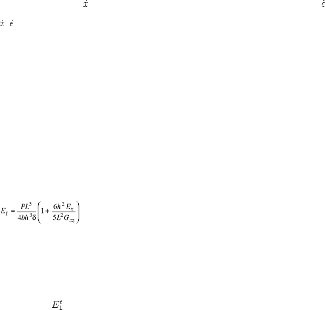
from the deflection δ according to (Ref 30):
(Eq 3)
where G
xz
is the interlaminar shear modulus in the x-z plane. The last term in Eq 3 is a shear correction factor
that may be significant for high axial modulus specimens with a low interlaminar shear modulus, that is, beams
with the fibers along the beam axis.
For beams with the fibers perpendicular to the beam axis, shear deformation is generally not significant in
bending, and the flexural modulus is given by the first term only:
E
f
= PL
3
/4bh
3
δ
(Eq 4)
A problem with the shear correction according to Eq 3 is that the extensional and shear moduli (E
x
and G
xz
)
must be known beforehand. For the purpose of correction, the extensional modulus E
x
is equivalent to the
tension modulus, , and the shear modulus can be approximated by the in-plane shear modulus, G
12
, if the
fibers are along the beam axis. If the shear correction factor cannot be determined, the flexural modulus can be
evaluated from Eq 4 at increasing span lengths until a constant value is achieved (see Fig. 17).
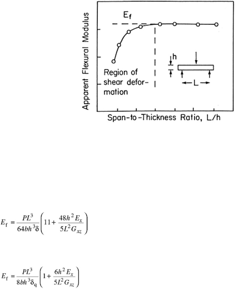
Fig. 17 Illustration of graphical method to determine flexural modulus free of influence of shear
deformation
Data Reduction for Four-Point Loading (Quarter Point). The flexural stress at the specimen surface in the
region between the inner load noses is given by:
σ = 3PL/4bh
2
(Eq 5)
If a strain gage is used, calculation of the stress from the load data and plotting stress versus strain allow
determination of flexural modulus and strength exactly as previously outlined for three-point loading. If load
and midspan deflection are measured, the flexural modulus is evaluated from:
(Eq 6)
where the symbols have the meaning as in Eq 3.
If the beam deflection is measured at the quarter points, which would be equal to the crosshead travel
compensated for test machine compliance, the flexural modulus is (Ref 30):
(Eq 7)
where δq is the deflection at quarter points. Since the shear correction is proportionally larger for the quarter-
point deflection formula Eq 7 than for the center deflection formula, Eq 6, shear deformation is less a factor for
a test conducted with center-deflection measurement.
Shear Testing
A shear test is performed to determine shear modulus and shear strength of a composite material. The response
of a material subjected to shear is commonly nonlinear, and full characterization requires the entire stress-strain
curve. The tests may be grouped as in-plane tests that relate to the structural response of plates and shells, and
interlaminar tests that relate to the behavior of local details such as joints. Figure 18 defines in-plane shear
stress, τ
xy
, and out-of-plane (interlaminar) shear stresses τ
xz
and τ
yz
. The corresponding shear moduli are denoted
by G
xy
, G
xz
and G
yz
and the corresponding shear strengths, S
6
, S
5
and S
4
, according to contracted stress notation.
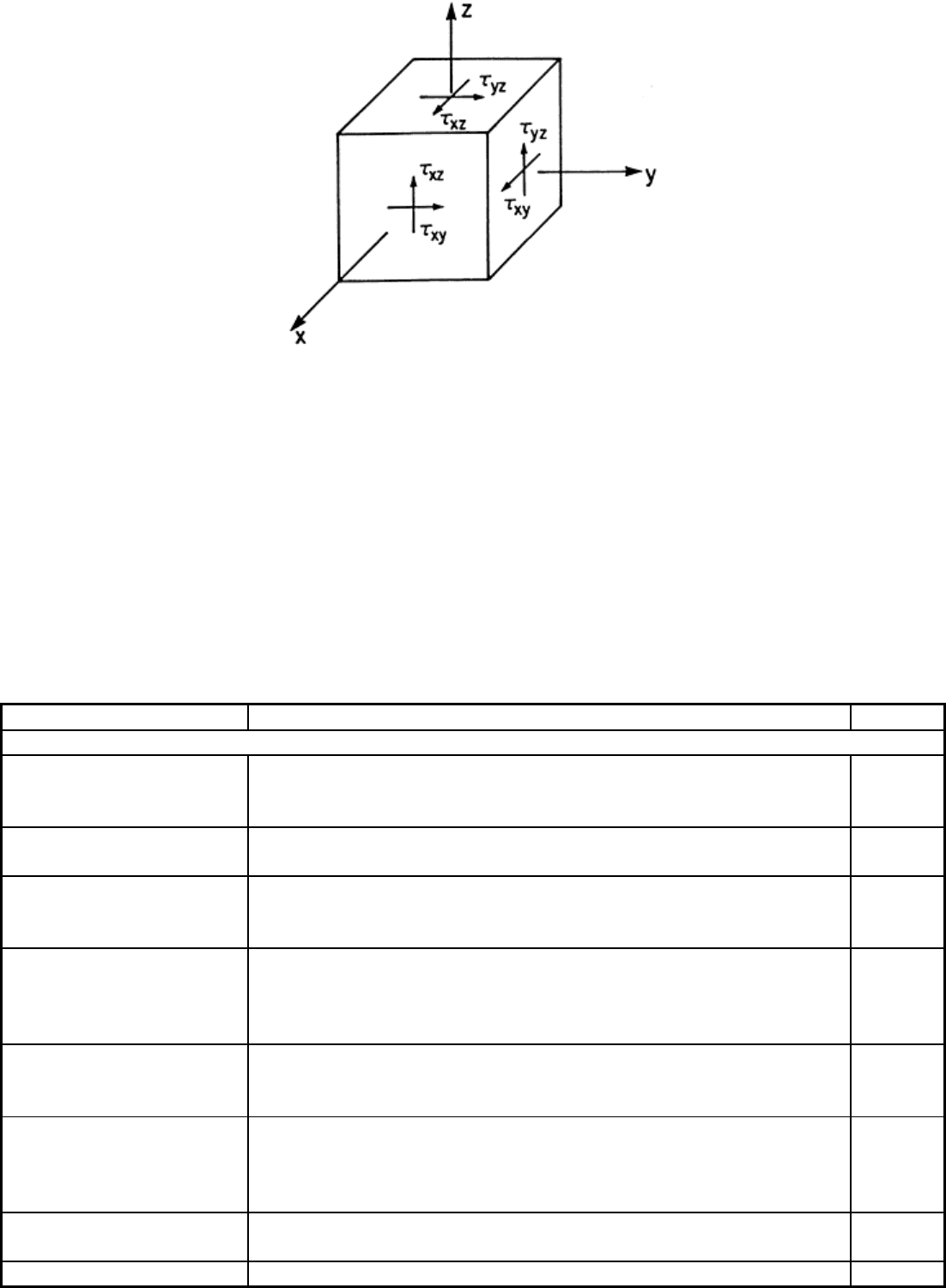
Fig. 18 Definition of shear stress components. τ
xy
is the in-plane shear stress, and τ
xz
and τ
yz
are out-of-
plane shear stresses.
The ideal shear test method should provide a region of pure, uniform shear stress. It is also required that the
shear stress and strain can be straightforwardly evaluated from the applied load and deformation measurements.
The major difficulty in designing shear tests for composite materials is attaining a uniform state of pure shear
stress in the test section. Many shear test methods exist as documented by Chatterjee et al. (Ref 10). Chatterjee
et al. (Ref 10) ranked the various shear test methods using the same criteria as for the previously discussed
compression test methods. Table 3 presents the various shear tests and their rankings. In this section, only the
methods with the highest ranking (1) are discussed except for the [±45°]
ns
tension test because of its popularity
in industry.
Table 3 Shear test methods for fiber-reinforced composites
Method Description Rating
(a)
In-plane shear
[±45°]
ns
, tension, ASTM D
3518, SACMA SRM 7-88
Ultimate strength and strain not acceptable for thin specimens. Study
required for effects of tabs and thickness. Effects of transverse tension
may be important in some cases.
2
Iosipescu, ASTM D 5379 Acceptable. Correction factor and measurement of all strains with
rosettes and back-to-back gages may be required.
1
Rail shear rectangular or
parallelogram, ASTM
Guide D 4255
Controlled 0° test required. 90° tests appear to yield good data.
Measurement of all strains may be required for [0/90°] lay-ups.
1
Torsion-circular bar Acceptable, but ultimate strains appear to be lower than Iosipescu and
rail shear. Data reduction procedure is simple but needs approval from
composites community. Machining required. Damage progression
needs study.
2
Torsion-rectangular bar Acceptable, but ultimate strains appear to be lower than Iosipescu and
rail shear. Data reduction procedure is complicated. Damage
progression needs study.
2
Torsion tube, ASTM
standard under
development
Excellent but expensive. Ultimate stress and strain levels high for
fibers parallel to longitudinal axis of tube. Effects of this and other
fiber orientations (hoop and slightly off from hoop) should be
compared.
1
Off-axis tension Acceptable only for modulus; correction factors based on aspect ratio
required
…
Picture frame or cross May be acceptable but more studies required. Tests are highly …
beam complicated.
Slotted shear, ASTM D
3846
Not acceptable for material property testing, possibly useful for
quality control.
…
Interlaminar shear
Iosipescu, ASTM D 5379 Thick specimens with bonded layers required. Appears to be the best
choice for unidirectional and fabric composites. Laminates may suffer
from free-edge effects because of small width.
1
Short beam shear, ASM D
2344, SACMA SRM 8-88
Three-point loaded specimens not acceptable because of local failure
near loading points and strong influence of bending stresses. Four-
point loaded specimens with optimized dimensions may perform
better.
…
(a) As rated in Ref 10; see discussion of Table 2 in text for general description of rating criteria.
Source: Ref 10
Short Beam Shear Test. The short beam shear test (ASTM D 2344) is a three-point flexure test with a span-to-
thickness ratio constrained to 4 to 1, forcing shear failure prior to tension or compression failure. The specimen
is all 0° lay-up, and the beam is usually 6.35 mm (0.25 in.) wide and between 2 and 3.5 mm (0.08 and 0.14 in.)
thick. The specimen length should be approximately 4h + 16 mm (4h + 0.6 in.), where h is the thickness. The
apparent shear strength is calculated as:
= 3P
ult
/4bh
(Eq 8)
The test does not always yield a pure shear failure and is not recommended for anything more than a quick and
inexpensive QC test of fiber/matrix adhesion.
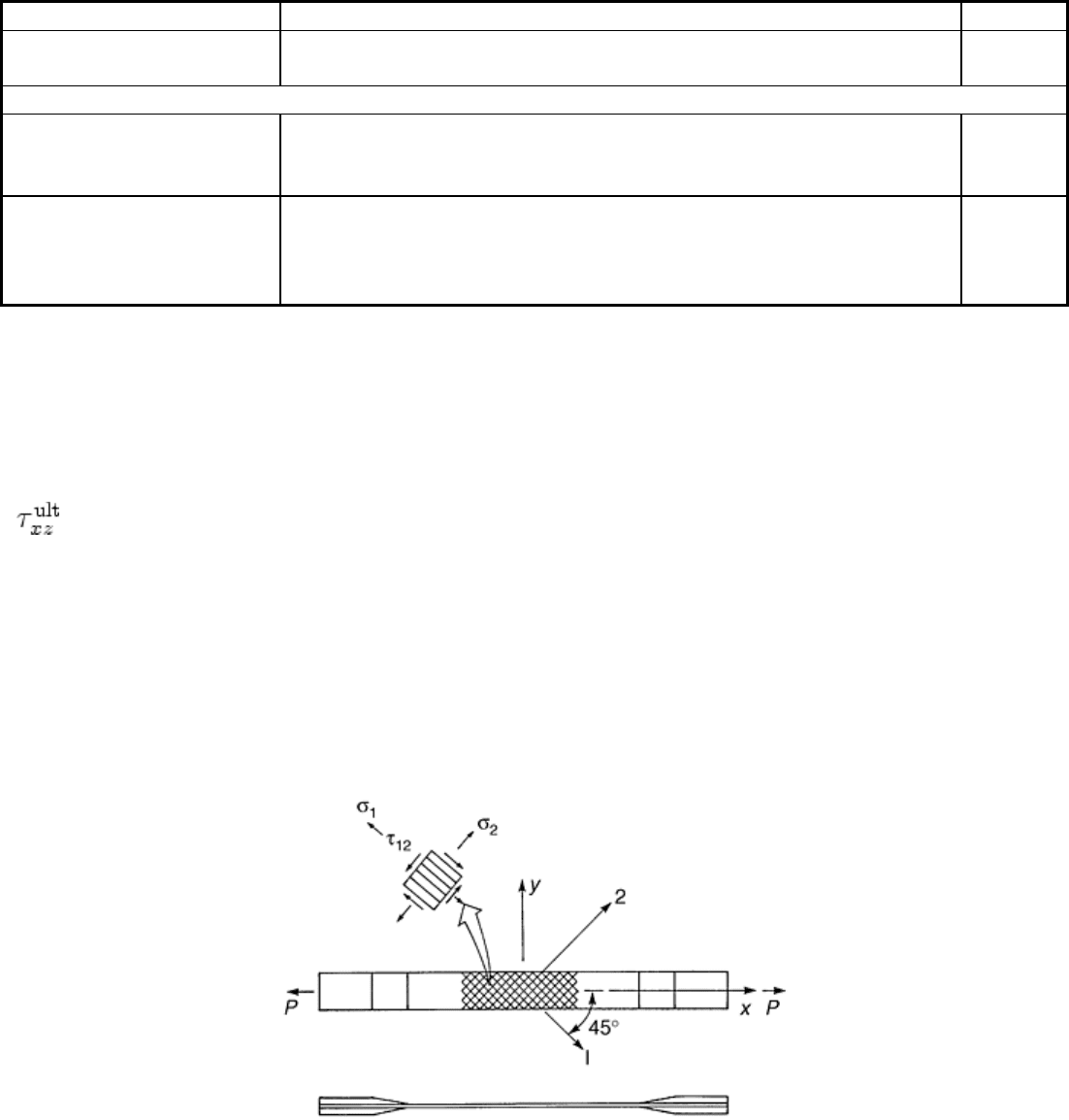
[±45°]
ns
Tension Test. The test geometry for the [±45°]
ns
tension specimen is shown in Fig. 19. The ASTM
standard D 3518 suggests the same specimen geometry as for the ASTM D 3039 tension test. The specimen
width typically ranges between 13 and 25 mm (0.5 and 1 in.). End tabs may not be required for polymer matrix
composites. The test measures the in-plane shear stress-strain response in the fiber coordinate system and is
only applicable for continuous fiber composites. Commonly, a [±45°]
ns
laminate is instrumented with a 0/90°
strain gage rosette as shown in Fig. 19. The specimen is prepared and tested in tension to ultimate failure
following the procedures outlined for the tension test.
Fig. 19 ASTM D 3518 [±45°]
ns
tension test specimen for evaluation of in-plane shear stress-strain
response of unidirectional composites
Determination of the lamina shear properties from the tension test requires stress analysis of the [±45°]
ns
specimen. Using laminated plate theory, Rosen (Ref 31) showed that the shear stress τ
12
(see Fig. 19), is simply
given by:
τ
12
= σ
x
/2
(Eq 9)
where σ
x
is the axial stress (P/A), and the shear strain is given by:
γ
12
= ε
x
- ε
y
(Eq 10)