ASM Metals HandBook Vol. 8 - Mechanical Testing and Evaluation
Подождите немного. Документ загружается.

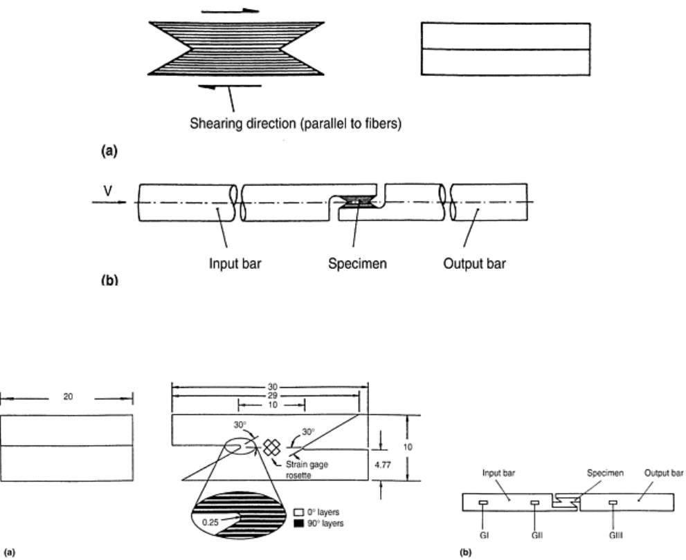
Fig. 45 Split-Hopkinson pressure bar testing to determine the interlaminar shear properties of
composites. (a) Optimum design of a single lap specimen. (b) Arrangement of the Hopkinson loading
bars.
Fig. 46 Modified single-lap specimen for Hopkinson pressure bar testing of composites. (a) Specimen
dimensions (in millimeters) and ply lay-up arrangement. (b) Arrangement of loading bars.
Test Details. Impact tests may be performed in a standard compression SHPB apparatus where a cylindrical
projectile fired from the high-pressure gas gun strikes the input loading bar. The force transmitted through the
specimen is recorded on the output bar strain gages, gage station GIII in Fig. 46. In analyzing the data, it is
assumed that the specimen central plane is the interlaminar failure plane and that the shear force is uniformly
distributed over this plane. Then the interlaminar shear stress may be determined directly from the output bar
strain gages.
The shear strain in the region of failure is measured using ±45° strain gage rosettes mounted on either side of
the specimen, as shown in Fig. 46. Signals from the specimen strain gage rosettes for an impact test on a plain-
weave carbon fiber reinforced plastic CFRP specimen are compared in Fig. 47 (Ref 75). In general, signals of
equal magnitude and opposite sign, ε
+45
= -ε
-45
, are obtained, indicating that on this scale the specimen is indeed
in a state of pure shear, the engineering shear strain being given by γ = 2ε
+45
= -2ε
-45
. A divergence between the
signals from the +45° and the -45° gages in the later stages of the test is apparent in Fig. 47, while at the end of
the test the +45° gages fail while the -45° gages unload. This is probably due to the failure plane not being the
central interlaminar plane. However a reasonable estimate of the engineering shear strain close to the failure
plane may be made from the algebraic sum of ε
+45
and ε
-45
. The average shear stress on the interlaminar plane
may be derived from the output bar strain gages so that, with allowance for the time delay for the stress wave to
travel between the specimen gages and the output bar gages, a shear stress-strain curve may be obtained. Quasi-
static and intermediate rate tests may be performed on the same design of specimen using shorter loading bars
and conventional testing machines to apply the load.
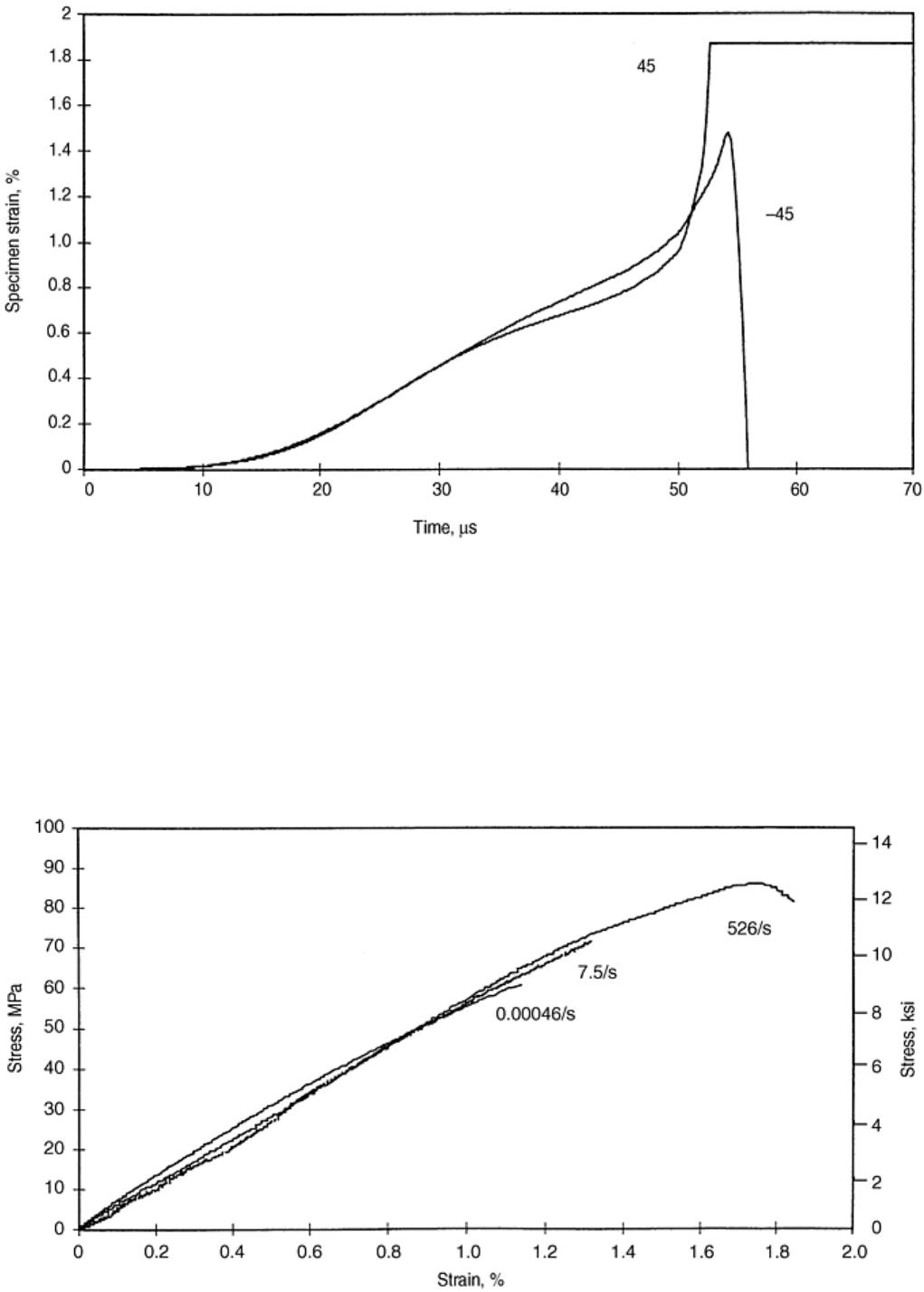
Fig. 47 Strain-time signals from specimen strain gages in impact testing of a plain-weave carbon-fiber
reinforced plastic single-lap specimen
Example Test Results. Stress-strain curves obtained in this way for cross-ply CFRP at a quasi-static, an
intermediate, and an impact rate of strain are shown in Fig. 48. The variation in interlaminar failure stress and
strain with strain rate, obtained from a set of five tests at each rate, are shown in Fig. 49. A marked increase in
interlaminar failure stress and strain with strain rate is apparent. It is clear from Fig. 48 that the shear modulus
is independent of strain rate. In an earlier study (Ref 73) where only the interlaminar failure stress was
measured, a somewhat smaller increase with strain rate was generally observed except for carbon/PEEK, where
no increase or a slight reduction was seen.
Fig. 48 Effect of strain rate on interlaminar shear stress strain curves for cross-ply carbon-fiber
reinforced plastic
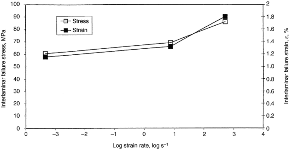
Fig. 49 Effect of strain rate on the interlaminar failure stress and strain
An impact test on a cross-ply CFRP specimen (Ref 74) has shown that failure does not occur on the
interlaminar plane nearest to the centerline between the notches but, rather on a neighboring plane, which lies
closer to the point where the notch tip radius on the input end meets the horizontal section of the notch. Since
each reinforcing ply has a finite thickness, the exact position of the plane on which failure occurs will clearly
depend on the precise position of the notch with respect to the lay-up. Nevertheless, the same result, that is
failure on a plane slightly offset from the centerline in this manner, was also observed in the earlier work on
unidirectional carbon/PEEK (Ref 76) where there was less constraint on the position of the failure plane.
Numerical Modeling of the Shear Test. In light of the experimental observation that failure does not occur on
the central interlaminar plane, a numerical analysis was performed (Ref 76) to investigate the shear and normal
stress distribution on the actual failure plane. For the cross-ply lay-up of Fig. 46, but simplified such that only a
single ply that, on the central plane, had the 90° orientation, the highest shear stress concentration was found in
the element where the notch tip radius joined the horizontal section of the notch, that is, at the input end of the
experimentally observed failure plane. The numerically predicted shear and normal stresses on this plane are
shown in Fig. 50. The mean shear stress in this figure corresponds to that which is measured experimentally.
The implication of the numerical analysis, therefore, is that failure actually initiates at a shear stress that is
approximately twice the mean shear stress determined experimentally and in the presence of a significant
normal compressive stress.
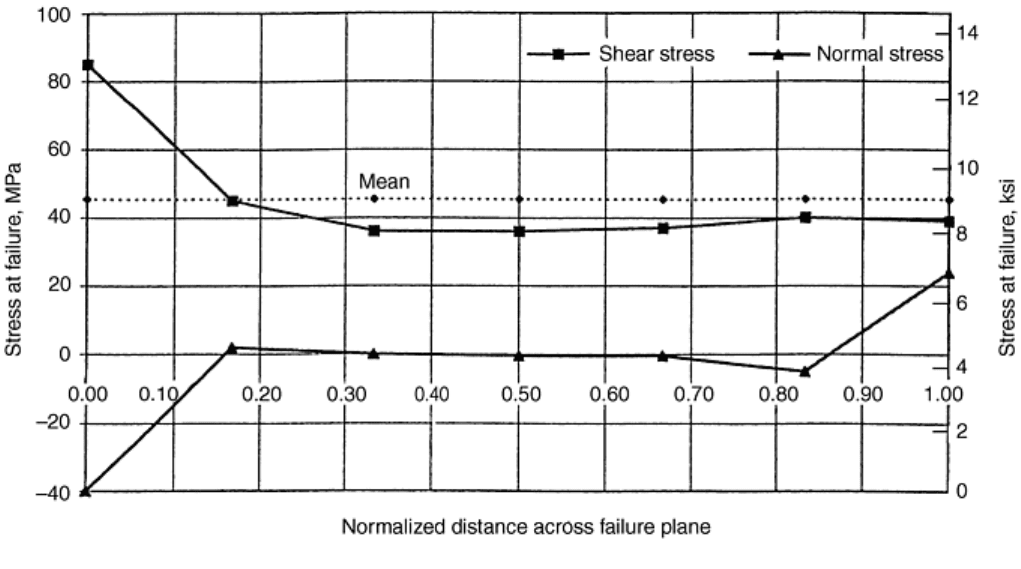
Fig. 50 Numerically predicted shear and normal stresses on actual failure plane
However, using a modification form of Chang-Chang failure criteria (Ref 77), we found it possible to predict
the initiation and growth of damage by delamination. This was predicted to start in the region of the shear stress
concentration at the input end of the failure plane, followed almost immediately by similar damage in the
corresponding element at the other end of the specimen and propagation from each end towards the center on
the two interlaminar planes, which are then joined by a step in the middle. Such a step has been seen
experimentally in unidirectionally reinforced specimens (Ref 76) but was not found in these tests on cross-ply
material. In similar tests on woven GFRP (Ref 75), complete failure on the first of these planes was mirrored by
extensive damage on the second.
Footnote
*
The section “Interlaminar Shear Properties of Fiber-Reinforced Composites a
t High Strain Rates” was written
by John Harding and Stephen Hallett, Oxford University. The section “Fatigue Testing and Behavior of Fiber-
Reinforced Composites” was written by W. Steven Johnson and Ramesh Talreja, Georgia Institute of
Technology.
References cited in this section
73. L.M. Dong and J. Harding, A Single-Lap Shear Specimen for Determining the Effect of Strain Rate on
the Interlaminar Shear Strength of Carbon-Fiber Reinforced Laminates, Composites, Vol 25, 1994, p
129–138
74. S.R. Hallett, C. Ruiz, and J. Harding, The Effect of Strain Rate on the Interlaminar Shear Strength of a
Carbon/Epoxy Cross-Ply Laminate: Comparison between Experiment and Numerical Prediction,
Compos. Sci. Technol., Vol 59, 1999, p 749–758
75. J. Harding and J.L. Medina, Oxford University Engineering Department, Solid Mechanics Group,
Unpublished data, August 1999

76. M.J. Hiley, L. Dong, and J. Harding, Effect of Strain Rate on the Fracture Process in Interlaminar Shear
Specimens of Carbon Fiber-Reinforced Laminates, Composites, Vol 28A, 1997, p 171–180
77. F. Chang and K. Chang, J. Compos. Mater., Vol 21, 1987, p 834–855
Mechanical Testing of Fiber-Reinforced Composites
Dale Wilson, The Johns Hopkins University, Leif A. Carlsson, Florida Atlantic University
Summary
While the single-lap shear test using the modified specimen geometry (Fig. 46), allows the effect of strain rate
on the interlaminar shear failure of laminated composites to determined, the shear stress on the failure plane is
not completely uniform, and failure initiates under a combination of stress concentrations in both shear and
normal compression. A similarly detailed analysis has not been performed for the optimum specimen geometry
(Fig. 45), so it is possible that the stress concentrations are less severe in this case. However, since in all
practical applications, interlaminar shear failure almost certainly initiates in the presence of stress
concentrations, the use of numerical analysis in conjunction with experimental testing becomes a necessity if
the results obtained are to be capable of useful application. It is encouraging, therefore, that by the use of a
modified Chang-Chang failure criterion, features actually observed in the single-lap shear test under impact
loading, in particular the initiation and growth of delamination damage associated with the failure plane, have
been successfully modeled numerically (Ref 74).
Footnote
*
The section “Interlaminar Shear Properties of Fiber-
Reinforced Composites at High Strain Rates” was written
by John Harding and Stephen Hallett, Oxford University. The section “Fatigue Testing and Behavior of Fiber-
Reinforced Composites” was written by W. Steven Johnson and Ramesh Talreja,
Georgia Institute of
Technology.
Reference cited in this section
74. S.R. Hallett, C. Ruiz, and J. Harding, The Effect of Strain Rate on the Interlaminar Shear Strength of a
Carbon/Epoxy Cross-Ply Laminate: Comparison between Experiment and Numerical Prediction,
Compos. Sci. Technol., Vol 59, 1999, p 749–758

Mechanical Testing of Fiber-Reinforced Composites
Dale Wilson, The Johns Hopkins University, Leif A. Carlsson, Florida Atlantic University
Fatigue Testing and Behavior of Fiber-Reinforced Composites
W. Steven Johnson and Ramesh Talreja, Georgia Institute of Technology
From the preceding discussions, one can see that the mechanical behavior of composites is complex and varied.
The mechanisms of fatigue damage are also complex. This section gives an overview of fatigue testing and
fatigue damage mechanisms for several classes of composite materials. Several types of mechanical
measurements that can be made during the course of testing to assess fatigue damage are reviewed. In addition,
some other destructive techniques that can be used to assess fatigue damage are described.
Footnote
*
The section “Interlaminar Shear Properties of Fiber-Reinforced Compo
sites at High Strain Rates” was written
by John Harding and Stephen Hallett, Oxford University. The section “Fatigue Testing and Behavior of Fiber-
Reinforced Composites” was written by W. Steven Johnson and Ramesh Talreja, Georgia Institute of
Technology.
Mechanical Testing of Fiber-Reinforced Composites
Dale Wilson, The Johns Hopkins University, Leif A. Carlsson, Florida Atlantic University
Fatigue Damage Mechanisms
Before attempting to predict life of composite components in service under cyclic loads, one should understand
the mechanisms of damage that govern the material behavior. For this purpose, posing the following questions
is useful:
• How does the material state (properties of constituents and interfaces) change from the initial to the
instant when the first maximum load is applied?
• On reversal of the load from maximum to the initial value, does the material return to its initial state,
and if not, what are the irreversible changes?
• How do the irreversible changes affect the response of the material to the next application of the load?
• What are the factors governing the progressiveness in the irreversible changes?
• What is the critical material state (failure), and how is it attained?
For metals, these questions have been addressed for many years, and the knowledge generated forms the basis
for safe and reliable structural design as well as for the development of fatigue resistant metals. For composites,
much remains to be done to reach the same level of progress. The problems faced for composites are complex
due to the roles of constituents and interfaces and the many possible configurations in which composites can be
made. It is inevitable that multiple fatigue mechanisms operate simultaneously with differing rates of
progression. To facilitate a systematic interpretation of the mechanisms, fatigue life diagrams have been useful
for polymer-matrix composites (PMCs) (Ref 78), ceramic-matrix composites (CMCs) (Ref 79), and metal-
matrix composites (MMCs) (Ref 80). In the following sections, the fatigue mechanisms for these material
systems are reviewed with the aid of these diagrams.
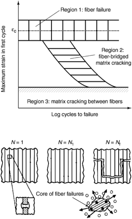
Fatigue Life Diagram. The basic construction of a fatigue life diagram is shown in Fig. 51 for a unidirectional,
continuous fiber reinforced PMC of standard materials (such as carbon/epoxy) subjected to cyclic tension in the
fiber direction. Consider first a load cycle in which the maximum strain attained is within the scatter band of the
composite failure strain. At the first application of the maximum load in this cycle, a certain number of fibers
will fail, assuming the composite survives. The locations of fiber breaks will be determined by the points at
which the fiber stress exceeded the fiber strength. A distributed pattern of fiber breaks will result (see Fig. 52, N
= 1), and the matrix around broken fibers will experience higher stresses than elsewhere and will likely become
inelastic. On reversal of the load to its minimum value, the inelastic strains will irreversibly change the material
state from the virgin state. In the next and subsequent load cycles, the axial stress in unbroken fibers will
progressively change. However, all cross sections containing broken fiber ends will not experience the same
rate of growth of fiber breaks, because of the variability of the fiber strength, and failure will result from a cross
section that can form a core of fiber failures of a critical size (see Fig. 52, N = N
f
).
Fig. 51 Fatigue life diagram of a unidirectional composite under cyclic tension in the fiber direction
Fig. 52 Mechanism of fiber failure in region I of the fatigue life diagram
It can now be imagined that the number of cycles to failure, N
f
depends on the fiber strength distribution, the
geometric distribution of fibers, the matrix deformation characteristics, and the critical size of the core of fiber
failures. For stiff and brittle fibers, the critical core size is expected to be small and the number of cycles needed
to reach it could vary from a few to several millions, depending on how the initial pattern of broken fibers is
formed. This extreme sensitivity to the first-cycle failure pattern overshadows the cycle-by-cycle progression of
the fiber failure process. Thus, region 1 in the fatigue life diagram (Fig. 51), where fiber failure is the dominant
mechanism, is viewed as a nonprogressive failure region. The scatter band here is centered about the fiber
failure strain, which is also the composite failure strain, and extends to infinite number of cycles.
Consider now a load cycle where the first application of load gives a maximum strain less than the lower limit
of the composite failure scatter band. The number of fibers failed in this cycle will be insignificant. In the next
and subsequent load cycles, the stress redistribution in the unbroken fibers due to matrix inelasticity would not
increase the number of fiber breaks significantly. The inelastic cyclic deformation of matrix will, however,
initiate fatigue cracks in the matrix, assuming that the local matrix strain exceeds its fatigue limit. The fatigue
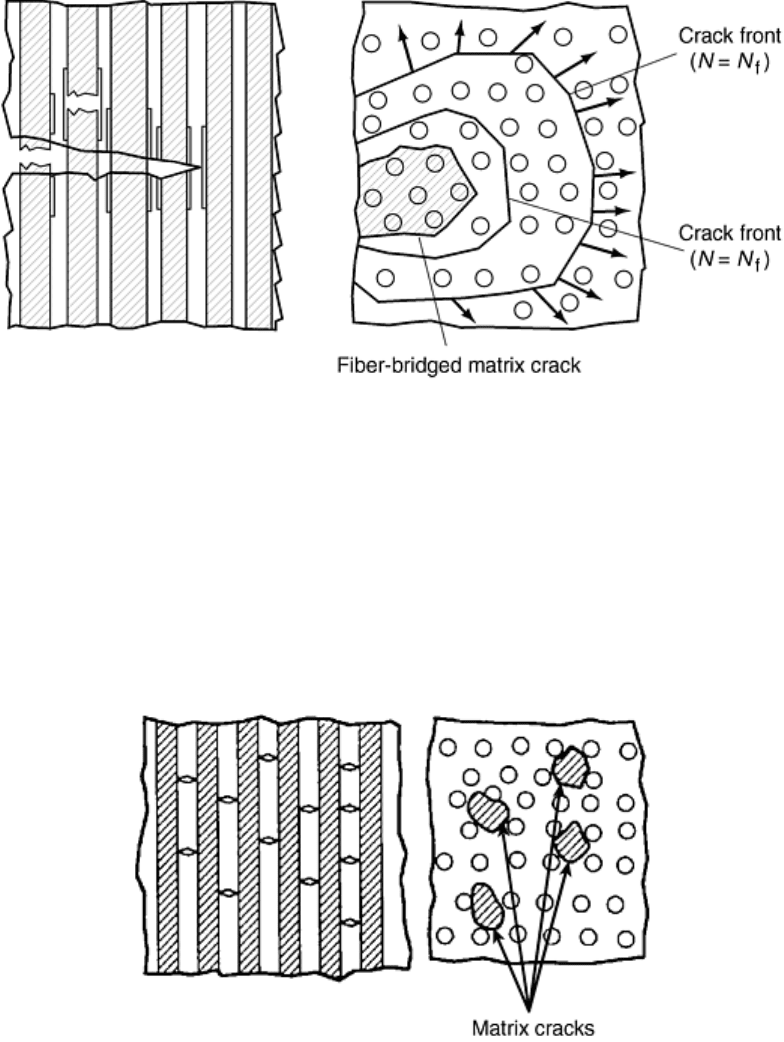
crack thus produced will grow progressively as a fiber- bridged crack, breaking some (weak) fibers while
debonding others and growing around them (Fig. 53). At a critical crack size, depending on the maximum load
applied, unstable crack growth will occur, resulting in composite failure.
Fig. 53 Mechanism of fiber-bridged matrix cracking in region II of the fatigue life diagram
This postulated sequence of events has been documented (Ref 78) for two PMC systems (Ref 81), and the
sloping scatter band in Fig. 51 (marked as region 2) represents this progressive mechanism. The rate of
progression of this mechanism depends on the maximum strain applied in the first load cycle. It is natural to
expect that a threshold value of the maximum strain exists, below which the mechanism either does not
progress (e.g., matrix cracks are not able to overcome the resistance given by fibers, Fig. 54) or does not cause
further damage (i.e., unstable growth) in a great number of cycles. The region in the fatigue life diagram below
such a threshold value is called the composite fatigue limit (region 3 in Fig. 51). It is expected that this
threshold value for a given composite will depend on the matrix fatigue limit, the fiber stiffness and strength,
the interface strength, and the distribution of fibers in the composite.
Fig. 54 Mechanism of matrix cracking arrested by fibers corresponding to region III of the fatigue life
diagram
Effects of Constituents on Fatigue Damage. The fatigue life diagram described for Fig. 51 is based on the
mechanisms expected to occur in standard PMCs such as glass/epoxy and graphite/epoxy. When the properties
of the constituents are varied, for example, by changing the fiber stiffness, fiber strain to failure, or matrix
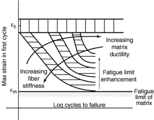
ductility, the mechanisms are affected and the resultant effects on the fatigue life can be easily understood by
observing changes in the fatigue life diagrams. For instance, an increase in the fiber failure strain will displace
region 1 upwards, while increasing fiber stiffness will delay matrix crack growth, shifting region 2 to the right
as indicated in Fig. 55. On the other hand, increasing matrix ductility will enlarge the crack-tip plastic zone,
thereby increasing crack-tip opening displacement and straining the bridging fibers further. The detrimental
effect on fatigue life by this change in the mechanism will shift region 2 (Fig. 51) to the left (Fig. 55). Finally,
improved fatigue properties of the matrix material and reduced fiber stiffness will raise the composite fatigue
limit, reducing thereby the range of strain in which fatigue failure can occur.
Fig. 55 Trends in the fatigue life diagram induced by fiber stiffness and matrix ductility
In high temperature materials, such as MMCs and CMCS, the residual stresses can be large. For instance, in
SCS-6/Ti-15-3, the residual stress on cooldown to the room temperature is compressive in the fibers. The
inelastic cyclic deformation can relieve this stress and thereby increase the probability of fiber failure. This
changes region 1 of the fatigue life diagram from having a horizontal scatter band of nonprogressive fiber
failure to a sloping scatter band of cycle-dependent progressive failure. At high temperatures, the residual
compressive stress in fibers decreases while the matrix inelastic deformation increases. These two effects
render the fiber failure mechanism of region 1 even more progressive. The slope of region 1, thus, increases
with increasing temperature (Ref 80).
In CMCs, where both constituents are brittle, the source of irreversibility in cyclic loading is provided primarily
by friction at the debonded fiber/matrix interfaces. The fiber stress redistribution with cycles is caused by load
transfer between matrix and fibers through the frictional shear stress at the interface. At room temperature, at
which the matrix behaves in a brittle manner, its role in the fatigue process is not significant. Region 1 and
region 2 of the fatigue life diagram are then not as easily separable as in PMCs and MMCs. The dominant
mechanism in both regions is fiber failure, whose progression is governed by the fiber/matrix interface. A
fatigue limit still exists but is not governed by the matrix. As discussed in (Ref 81), the fatigue limit in this case
is given by the threshold below which the rate at which fibers are broken in a cycle is exceeded by the rate at
which fibers bridge the matrix crack.
Effects of Fiber Architecture. In multidirectional laminates, other mechanisms in addition to those previously
described come into play. These additional mechanisms consist primarily of multiple intralaminar cracking of
off-axis plies and interlaminar cracking (delamination). These mechanisms can be viewed as subcritical, while
those associated with failure of on-axis plies should be viewed as critical. The role of the subcritical
mechanisms is thus seen as effecting stress transfer from off-axis plies to on-axis plies. This stress transfer
occurs progressively, and failure occurs when the on-axis plies are stressed to their limiting value.
The progression of intralaminar cracking in off-axis plies is conveniently described by the evolution of the
average number of cracks per unit length normal to the crack planes (or inverse of the average crack spacing).
This crack density parameter is shown plotted against the number of load cycles of different maximum load
value for a glass/epoxy cross ply laminate in Fig. 56. The evolution rate of this parameter depends on the
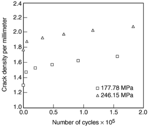
laminate geometry, that is, the thickness of the off-axis plies and the stacking sequence of the laminate, and the
relative stiffness of the off-axis plies with respect to the on-axis plies.
Fig. 56 Evolution of transverse cracking under fatigue in a glass/epoxy cross-ply laminate at two stress
amplitude. Data from Ref 82
The interlaminar cracking, that is, delamination, results from the local failure of the ply/ply interface due to the
high (and complex) stress accompanying the fronts of the intralaminar cracks and by diversion of these fronts
into the interlaminar planes. These distributed delaminations grow under cyclic loading and are thought to be
responsible for altering the stress states in the plies, giving rise to the progressive cracking of the off-axis plies.
In woven fabric composites, the fiber bundles develop multiple cracks in much the same way as intralaminar
cracks in laminates. The interbundle planes crack in the crossover regions of the bundles and presumably play a
role similar to that of delaminations in laminates.
Footnote
*
The section “Interlaminar Shear Properties of Fiber-
Reinforced Composites at High Strain Rates” was written
by John Harding and Stephen Hallett, Oxford University. The section “Fatigue Testing and Behavior of Fiber-
Reinforced Composites” was written by W. Steve
n Johnson and Ramesh Talreja, Georgia Institute of
Technology.
References cited in this section
78. R. Talreja, Fatigue of Composite Materials: Damage Mechanisms and Fatigue Life Diagrams, Proc. R.
Soc. (London), Vol A378, 1981, p 461–475
79. R. Talreja, “Fatigue of Fiber-Reinforced Ceramics”, Structural Ceramics—Processing, Manufacture
and Properties, J.J. Bentzen, et al., Ed., Riso National Laboratory, Roskilde, Denmark, 1990, p 145–159
80. R. Talreja, A Conceptual Framework for Interpretation of MMC Fatigue, Mater. Sci. Eng., Vol A200,
1995, p 21–28
81. E.K. Gamstedt and R. Talreja, Fatigue Damage Mechanisms in Unidirectional Carbon-Fiber-Reinforced
Plastics, J. Mater. Sci., 1999, in press
82. A.L. Highsmith and K.L. Reifsnider, Stiffness Reduction Mechanisms in Composite Laminates,
Damage in Composite Materials, K.L. Reifsnider, Ed., ASTM STP 775, 1982, p 103–117