Basu P. Biomass Gasification and Pyrolysis: Practical Design and Theory
Подождите немного. Документ загружается.


207
6.8 Gasifier Sizing
Updraft Gasifier
Updraft gasifiers are one of the simplest and most common types of gasifier
for biomass. The maximum temperature increases when the feed of air or
oxygen increases. Thus, the amount of oxygen feed for the combustion reaction
is carefully controlled such that the temperature of the combustion zone does
not reach the slagging temperature of the ash, causing operational problems.
The gasification temperature may be controlled by mixing steam and/or flue
gas with the gasification medium.
The hearth load of an updraft gasifier is generally limited to 2.8
MW/m
2
or
150
kg/m
2
/h for biomass (Overend, 2004). For coal it might be higher. In an
oxygen-based coal gasifier, for example, the hearth load of a moving bed can
be greater than 10
MW/m
2
. A higher hearth load increases the space velocity
of gas through the hearth, fluidizing finer particles in the bed. Probstein and
Hicks (2006) quote space velocities for coal on the order of 0.5
m/h for steam–
air gasification and 5.0
m/h for steam–oxygen gasification. Excessive heat
generation in such a tightly designed gasifier may cause slagging. Based on the
characteristics of some commercial updraft coal gasifiers, Rao et al. (2004)
suggest a specific grate gasification rate as 100 to 200
kg fuel/m
2
h for RDF
pellets, with the gas-to-fuel ratio in the range 2.5 to 3.0. Carlos (2005) obtained
a rate of 745 to 916
kg/m
2
h with air–steam and air preheat at temperatures of
350 and 830 °C, respectively.
For an updraft gasifier, the height of the moving bed is generally greater
than its diameter. Usually, the height-to-diameter ratio is more than 3
:
1
(Chakraverty et
al., 2003). If the diameter of a moving bed is too large, there
may be a material flow problem, so it should be limited to 3 to 4 m in diameter
(Overend, 2004).
Downdraft Gasifier
As we saw in Figures 6.4 and 6.6, the cross-sectional area of a downdraft gasifier
may be nonuniform; it is narrowest at the throat. The hearth load is, therefore,
based on the cross-sectional area of the throat for a throated gasifier, and for a
throatless or stratified downdraft gasifier, it is based on the gasifier cross-
sectional area. The actual velocity of gas is, however, significantly higher than
the designed space velocity because much of the flow passage is occupied by fuel
particles. The velocity is higher in the throat also because of the higher tempera-
ture there. Table 6.6 gives some characteristic values of these parameters.
In a downdraft gasifer, the gasification air is injected by a number of nozzles
from the periphery (refer to Figure 6.6). The total nozzle area is typically 7 to
4% of the throat area. The number of nozzles should be an odd number so that
the jet from one nozzle does not hit a jet from the opposite side, leaving a dead
space in between. To ensure adequate penetration of nozzle air into the hearth,
the diameter of a downdraft gasifier is generally limited to 1.5
m. This naturally
restricts the size and capacity of a downdraft gasifier.

208
chapter
|
6 Design of Biomass Gasifiers
Table 6.7 lists typical sizes for the Imbert-type downdraft gasifier and shows
the relation between throat size and air nozzle diameter.
6.8.2 Fluidized-Bed Gasifiers
No established design method for sizing a fluidized-bed gasifier is available in
the literature because, though nearly a century old, this type is still evolving.
This section presents a tentative method for determining size based on available
information.
Cross-Sectional Area
The inside cross-sectional area of the fluidized-bed gasifier, A
b
, is found by
dividing the volumetric flow rate of the product gas flow, V
g
, by the chosen
superficial gas or fluidization velocity through it, U
g
, at the operating tempera-
ture and pressure.
A
V
U
b
g
g
= (6.29)
The volume of gas at the operating temperature and pressure, V
g
, is esti-
mated from the mass of air (or other medium), M
fa
, required for gasification
(Eq. 6.29) as well as for fluidization. Thus, V
g
is necessarily the gas passing
through the grate and the bed.
TABLE 6.6 Hearth Load for Downdraft Gasifiers Maximum Values
Based on Throat Area
Plant
Gasifier
Type Medium
D
throat
(m)
D
air entry
(m)
Superficial
Velocity
at Throat
(m/s)
Hearth
Load*
(MW/m
2
)
Gengas Imbert Air 0.15 0.3 2.5 15
Biomass Corp. Imbert Air 0.3 0.61 0.95 5.7
SERI Throatless Air 0.15 0.28 1.67
Buck Rogers Throatless Air 0.61 0.23 1.35
Buck Rogers Throatless Air 0.61 0.13 0.788
Syngas Throatless Air 0.76 1.71 10.28
Syngas Throatless Oxygen 0.76 1.07 12.84
SERI Throatless Oxygen 0.15 0.24 1.42
*Based on throat area.
Source: Data compiled from Reed and Das, 1988, p. 36.

TABLE 6.7 Sizes of Imbert-Type Gasifiers
d
r
/d
h
(–)
d
h
(mm)
d
r
(mm)
d
r′
(mm)
h
(mm)
H
(mm)
R
(mm)
A
(no.)
d
m
(mm)
Range of Gas
Output (Nm
3
/h)
Maximum Wood
Consumption (kg/h)
Air Blast
Velocity (m/s)
268/60 60 268 150 80 256 100 5 7.5 4–30 14 22.4
300/100 100 300 208 100 275 115 5 10.5 10–77 36 29.4
400/130 130 400 258 110 370 155 7 10.5 17–120 57 32.6
400/150 135 400 258 120 370 155 7 12 21–150 71 32.6
400/175 175 400 308 130 370 155 7 13.5 26–190 90 31.4
400/200 200 400 318 145 370 153 7 16 33–230 110 31.2
Variables not defined in the figure are defined as follows:
d
m
= inner diameter of the tuyere
A = number of tuyeres
Source: Data compiled from Reed and Das, 1988.

210
chapter
|
6 Design of Biomass Gasifiers
In some designs, part of the gasifying medium is injected above the distribu-
tor grid. In that case, V
g
is only the amount that passes through the grid. We
can use the mass of gasification medium, M
fa
, required for gasification for the
computation of V
g
:
V
M
g
fa
g
=
ρ
(6.30)
where ρ
g
is the density of the medium at the gasifier’s operating temperature
and pressure.
Equation (6.29) requires choosing an appropriate value for the superficial
gas (fluidizing) velocity, U
g
, through the gasification zone. This is critical as it
must be within acceptable limits for the selected particle size to ensure satisfac-
tory fluidization and to avoid excessive entrainment.
Fluidization Velocity
The range of fluidizing velocity, U
g
, in a bubbling bed depends on the mean
particle size of the bed materials. The choice is made in the same way as for a
fluidized-bed combustor. The range should be within the minimum fluidization
and terminal velocities of the mean bed particles. The particle size may be
within group B or group D of Geladart’s powder classification (see Basu, 2006,
Appendix I). The typical fluidization velocity for silica sand of about 1 mm
mean diameter may, for example, vary between 1.0 and 2.0
m/s.
If the gasifier reactor is a circulating fluidized-bed type, the fluidization
velocity in its riser (Figure 6.12) must be within the limits of fast fluidization,
which favors groups A or group B particles. Typical fluidization velocity for
particle size in the range 150 to 350 microns is 3.5 to 5.0 m/s in a CFB. This
type of bed has another important operating condition to be satisfied for opera-
tion in the CFB regime. Solids, captured in the gas–solid separator at the gasifier
exit, must be recycled back to the gasifier at a rate sufficiently high to create a
“fast-fluidized” bed condition in the riser. Additional details about this are
available in Basu (2006) or Kunii and Levenspiel (1991).
Gasifier Height
Since gasification involves only partial oxidation of the fuel, the heat released
inside a gasifier is only a fraction of the fuel’s heating value, and part of it is
absorbed by the gasifier’s endothermic reactions. Thus, it is undesirable to
extract any further heat from the main gasifier column. For this reason, the
height of a fluidized-bed gasifier is not determined by heat-transfer consider-
ations as for fluidized-bed boilers. Instead, gas and solid residence times are
major considerations.
The total height of the gasifier is made up of the height of the fluidized bed
and that of the freeboard above it:
Total gasifier height bubbling bed height depth freeboard=
( )
+ height (6.31)

211
6.8 Gasifier Sizing
Fluidized-Bed Height
The bed height (or depth) of a bubbling fluidized-bed gasifier is an important
design parameter. Gas–solid gasification reactions are slower than combustion
reactions, so a bubbling-bed gasifier is necessarily deeper than a bubbling-bed
combustor, which is typically 1.0- to 1.5-m deep for units larger than 1
m in
diameter. Besides pilot plant data or design experience, there is presently no
simple means of deciding the bed depth. A deeper bed allows longer gas resi-
dence time, but the depth should not be so great compared to its diameter as to
cause slugging. The selection of bed height depends on economics. A higher
bed height means a higher pressure drop and also a taller reactor. It also should
provide a longer residence time for better carbon conversion.
The gasification agent, CO
2
or H
2
O, entering the grid takes a finite time to
react with char particles to produce the gas. The bulk of the gasifying agent
travels up through the bubbles but very little reaction takes place in the bubble
phase. Rather, the reaction takes place mostly in the emulsion phase. The extent
to which oxygen or steam is converted into fuel gases thus depends on the gas
exchange rate between the bubble and emulsion phases as well as on the char-
gas reaction rate in the emulsion phase. This is best computed through a kinetic
model of the gasifier as illustrated in Section 5.6.2. An alternative is to use an
approach based on residence time, as described next.
Residence Time Design Approach
A bubbling fluidized bed must be suffi-
ciently deep to provide reactants the time to complete the gasification reactions.
This is why residence time is an important consideration for determination of
bed height. An approach based on residence time, developed primarily for coal
gasification, can be used for biomass char gasification, which gives at least a
first estimate of the bed height for a biomass-fueled bubbling fluidized-bed
gasifier.
The residence time approach is based on the assumption that the conversion
of char into gases is the slowest of all gasifier processes, so the reactor should
provide adequate residence time for the char to complete its conversion to the
desired level. Here is a simplified method.
Given the following assumption:
The reactivity factor is f
o
, = 1 (which lies between 0 < f
o
≤ 1).
The solid is in a perfectly mixed condition (i.e., continuous stirred-tank
reactor).
Then, the volume of the fluidized bed, V, is calculated using the equation
V
W
out
b
=
θ
ρ
(6.32)
where W
out
is the char moving out; kg/s = (1−X) W
in
; X is the fraction of the
char in the converted feed; ρ
b
is the bed density, which can be estimated
212
chapter
|
6 Design of Biomass Gasifiers
theoretically from fluidization hydrodynamics and regime (kg/m
3
); and θ is the
residence time of the char in the bed, or reaction time (s).
The residence time approach assumes that the water–gas reaction, (C +
H
2
O → CO + H
2
), as written in Eq. (6.33) is the main gasification reaction,
where the char is consumed primarily by the steam gasification reaction for
nth-order kinetics:
1
2
m
dC
dt
k
n
=
[ ]
H O (6.33)
where m is the initial mass of the biomass and C is the total amount of carbon
gasified in time, t. Taking a logarithm of this,
ln ln ln
1
2
m
dC
dt
k n
=
( )
+
[ ]
H O (6.34)
experiments can be carried out taking a known weight of the biomass and
measuring the change in carbon conversion at different time intervals for a
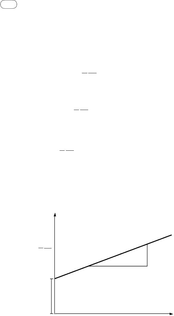
given temperature, steam flow, and pressure. Using these data, graphs are
plotted between
ln
1
m
dC
dt
and ln[H
2
O]. The y-intercept in this graph will
give the value of k, and the slope will give the value of n. An example of such
a plot is shown in Figure 6.23.
The experiment is carried out for different operating temperatures such
as 700 °C, 800 °C, and 900 °C, so, for each temperature, one k value is
obtained.
ln[H
2
O]
ln
( )
1
k
n
m
dC
dt
FIGure 6.23 Plot of Eq. (6.34) for determination of residence time.

213
6.8 Gasifier Sizing
Now k can be expressed as
k k
E
RT
k k
E
RT
a
a
= −
= −
0
0
exp
ln ln
(6.35)
This shows that if we plot a graph between ln k and 1/T, the y-intercept will
give the value of k
0
and the slope will give the value of (−E
a
/R).
The reaction rate for the steam gasification of biomass is given by
dC
dt
k m
E
RT
a
n
= −
[ ]
0 2
exp H O (6.36)
This gives the generalized reaction rate that shows the dependence of the gas-
ification rate on temperature, mass of carbon or char, and concentration of
steam/air/oxygen.
From a knowledge of the reaction rate, the residence time, θ, can be calcu-
lated as
θ
= C
X
r
0
(6.37)
where C
0
is the initial carbon in the biomass particle, kg; X is the required
carbon conversion (−); and r is the steam gasification reaction rate (kg/s). We
can avoid such experiments if there is a suitable expression for the rate of steam
gasification of the designed biomass char (Sun et
al., 2007).
From knowledge of the required solid residence time, θ, then, the bed
volume, V
bed
, is
V
F C
x
bed
s char
=
[ ]
−
( )
θ
ε ρ
1
(6.38)
where F[C] is the char feed rate into the gasifier and ρ
s
is the density of the
bed solids. In a typical bubbling bed, the bed voidage is ~0.7. The bed generally
contains 5 to 8% (by weight) of reacting char (x
char
); the remaining solids are
inert bed materials.
The bed height, H
bed
, is known by dividing bed volumer by the bed area,
A
b
, which is known from chosen superficial velocity
H
V
A
bed
bed
b
= (6.39)
Design charts for residence time, θ, of test coals for different feed conver-
sions and S/C or O/C ratios are given in the Coal Conversion Systems Technical
Data Book (U.S. DOE, 1978). The residence time may be adjusted for the
reactivity of the char in question and for the reactivity of its partial gasification
before it enters the gasifier.

214
chapter
|
6 Design of Biomass Gasifiers
Other Considerations
Although virgin biomass contains little or no sulfur, some waste biomass fuels
do. For these, limestone is fed into the fluidized-bed gasifier for in-bed sulfur
removal. The height of the gasifier (freeboard and bed) should be adequate to
allow the residence time needed for the desired sulfur capture.
The tar produced should be thermally cracked inside the gasifier as far as
possible. Therefore, the depth of the gasifier should be such that the gas resi-
dence time is adequate for the desired tar conversion/cracking.
The deeper the bed, the higher the pressure drop across it and the higher
the pumping cost of air. Because bubble size increases with bed height, a deeper
bed gives larger bubbles with reduced gas–solid mixing. Furthermore, if the
bubble size becomes comparable to the smallest dimension of the bed cross-
section, a highly undesirable slugging condition is reached. This imposes
another limit on how deep the dense section of a fluidized bed can be.
Some biomass char, like that from wood, is fine and easily undergoes attri-
tion in a fluidized bed. In such cases a deeper bed may not guarantee a longer
residence time (Barea, 2009). Here, special attention must be paid to capturing
the char and either combusting it in a separate chamber to provide heat required
by the gasifier, or reinjecting it at an appropriate point in the bed where solids
are descending.
A kinetic model (nth-order, shrinking particle, and shrinking core) may also
be used to determine the residence time, the net solid holdup, and therefore the
height of the dense bed.
Freeboard Height
Entrainment of unconverted fine char particles from the bubbling bed is a major
source of carbon loss. The empty space above the bed, the freeboard, allows
entrained particles to drop back into it. A bubbling, turbulent, or spouted fluid-
ized bed must have such a freeboard section to help avoid excessive loss of bed
materials through entrainment and to provide room for conversion of finer
entrained char particles. The freeboard height must be sufficient to provide the
required residence time for char conversion. It can be determined from experi-
ence or through kinetic modeling.
A larger cross-sectional area and a taller freeboard increase the residence
time of gas/char and reduce entrainment. From an entrainment standpoint, the
freeboard height need not exceed the transport disengaging height (TDH) of a
bed because no further reduction in entrainment is achieved beyond this.
6.9 entraIned-Flow GasIFIer desIGn
Because the gas residence time in an entrained-flow reactor is very short—
on the order of a few seconds—to complete the reactions, the biomass particles
must be ground to extremely fine sizes (less than 1
mm). The residence time

215
6.9 Entrained-Flow Gasifier Design
requirement for the char is thus on the order of seconds. Section 6.9.1
describes some important considerations for entrained-flow gasifier design.
Although an entrained-flow gasifier is ideally a plug-flow reactor, in practice
this is not necessarily so. The side-fed entrained-flow gasifier, for example,
behaves more like a continuous stirred-tank reactor (CSTR). As we saw in
Figure 6.15, at a certain distance from the entry point, fuel particles may have
different residence times depending on the path they took to arrive at that
section. Some may have traveled a longer path and so have a longer residence
time. For this reason, a plug-flow assumption may not give a good estimate of
the residence time of char.
6.9.1 Gasifier chamber
Most commercial entrained-flow gasifiers operate under pressure and therefore
are compact in size. Table 6.8 gives data on some of these operating in the
United States and China.
A typical downflow entrained-flow gasifier is a cylindrical pressure vessel
with an opening at the top for feed and another at the bottom for discharge of
ash and product gas. The walls are generally lined with refractory and insulating
materials, which serve three purposes: (1) they reduce heat loss through the
wall, (2) they act as thermal storage to help ignition of fresh feed, and (3) they
prevent the metal enclosure from corrosion.
TABLE 6.8 Characteristic Sizes of Some Entrained-Flow Gasifiers
Gasifier
Volume
(m
3
)
Reactor External
Diameter (m)
Reactor Internal
Diameter (m)
Reactor
Height (m)
Tennessee
Eastman
12.7 2.79 1.67 4.87
Cool water 17 3.17 2.13 3.73
Cool water 25.5 3.17 2.13 6
Cool water 12.7 2.79 1.67 4.62
Shandong
fertilizer
12.7 2.79 1.67 4.87
Shanghai
Chemical
12.7 2.79 1.67 4.87
Harbei fertilizer 12.7 2.79 1.67 4.87
Source: Data compiled from Zen, 2005.

216
chapter
|
6 Design of Biomass Gasifiers
The thickness of the refractory and insulation used is to be chosen with care.
For example, biomass ash melts at a lower temperature and is more corrosive
than most coal ash, so special care needs to be taken in designing the gasifier
vessel for biomass feedstock.
The construction of a side-fed gasifier is more complex than that of a top-fed
gasifier, as the reactor vessel is not entirely cylindrical and requires numerous
openings. The bottom opening is for the ash drain, the top opening is for the
product gas, and the side ports are for the feed. Additional openings may also
be required depending on the design. Because of the complexity in the design
of a pressure vessel operating at 30 to 70 bars and temperatures exceeding
1000 °C, any additional openings or added complexity in the reactor configura-
tion must be weighed carefully against perceived benefits and manufacturing
difficulties.
6.9.2 auxiliary Items
The following subsections discuss the design of auxiliary systems in fluidized-
bed gasifiers.
Position of Biomass Feeding Position
The feed points for the biomass should be such that entrainment of any particles
in the product gas is avoided. This can happen when the feed points are located
too close to the expanded bed surface of a bubbling fluidized bed. If they are
in close proximity to the distributor plate, excessive combustion of the volatiles
in the fluidizing air produced can occur. To avoid this, they should be some
distance further above the grate.
Nascent tar is released close to the feed point, so tar cracking can be impor-
tant for some designs. If tar is a major concern, the feed port should be close
to the bottom of the gasifier so that the tar has adequate residence time to crack
(Barea, 2009).
Distributor Plate
The distributor plate of a fluidized bed supports the bed materials. It is no dif-
ferent from that used for a fluidized combustor or boiler. The ratio of pressure
drop across the bed and that across the distributor plate must be estimated to
arrive at the plate design. More details are available in books on distributor
plate design, including Basu (2006, Chapter 11). The typical open area in the
air distributor grate is only a few percentage points.
Bed Materials
For the process design of a fluidized-bed gasifier, the choice of bed materials
is crucial. These comprise mostly granular inorganic solids and some (<10%)
fuel particles. For biomass, sand or other materials are used (as explained next);