Becker W. Advanced Time-Correlated Single Photon Counting Techniques
Подождите немного. Документ загружается.

7.2 Optical Systems 295
checked. Filter fluorescence can be distinguished from afterpulsing by changing
the detector gain; afterpulsing changes with the gain, filter fluorescence does not.
7.2.12 Instability in PMTs
The gain of a PMT increases steeply with the supply voltage. If the gain is in-
creased above a safe level instability may occur. Instability shows up a sudden
increase of the background count rate. The rate can jump up to millions of counts
per second and even damage the PMT if it persists for several seconds. Usually
the count rate can be brought back to a reasonable level by decreasing the supply
voltage.
Like afterpulsing, instability is probably caused by ion feedback and possibly
luminescence of dynodes. Therefore some manufacturers specify not only a maxi-
mum operating voltage for their PMTs but also a maximum safe gain.
A PMT can develop instability or permanently increased dark count rate after
being heavily overloaded for a period of several seconds or longer. The reason is
probably heating of the anode and the last dynodes which releases gas from these
structures.
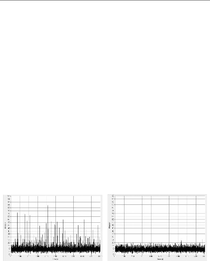
Signs of beginning instability are extremely strong afterpulsing, an unstable
counting background, and spikes in intensity traces recorded at millisecond resolu-
tion. An example is shown in Fig. 7.32., left. If a PMT shows signs of instability
an attempt can be made to operate it at a reduced voltage. If the reason of the in-
stability is not poor vacuum but exceptionally high gain, it may work reasonably
at the reduced operating voltage, see Fig. 7.32, right.
Fig. 7.32 Instability in a PMT, intensity traces recorded at a resolution of 1 ms per time
channel, time scale 1 s/div. The spikes in the recorded count rate (left) indicate beginning
instability. The same PMT works reasonably at reduced gain (right)
Instability or detector damage should not be confused with the normal behaviour
of a PMT after exposure to daylight. If the cathode is exposed to strong light with no
supply voltage applied, the dark count rate may be increased by one or two orders of
magnitude. A PMT that has been exposed to daylight will return to a normal dark
count level after some time in the dark. The recovery time can be from some min-
utes to about one day; see Fig. 6.19, page 233. If a PMT shows a substantially in-
creased dark count rate and does not recover within 1
2 days, it is damaged.
296 7 Practice of TCSPC Experiments
7.2.13 Timing Stability
The shortest IRF obtained with TCSPC and MCP PMTs is currently 25 to 30 ps.
With some 10
6
recorded photons the variance of the first moment of the IRF is of
the order of 10 fs. A statistical accuracy on this level is indeed confirmed by dis-
tance measurements based on TCSPC [340, 341]. A change in the first moment is
directly related to a change in a fluorescence lifetime. One could therefore pre-
sume that TCSPC reveals lifetime effects down to the time scale of a few 10 fs.
In practice the resolution of TCSPC is determined mainly by systematic timing
drift. The most critical parts of the system are the PMT and its voltage divider.
Changes in the count rate induce changes in the voltage distribution across the dyn-
odes and, consequently, changes in the transit time. The prospects are best for PMTs
with a low transit time and a fast single-electron response (SER). The fast SER
results in a correspondingly small anode current at a given count rate, and the low
transit time in correspondingly low transit-time change with the dynode voltages.
Figure 7.33 and Fig. 7.34 show the count-rate dependent timing drift of the IRF
for an XP2020 linear-focused PMT and an H5773
20 photosensor module. The
curves were recorded with a BHL
600 diode laser of 40 ps pulse width and 650 nm
wavelength, and an SPC
140 TCSPC module (both Becker & Hickl, Berlin). The
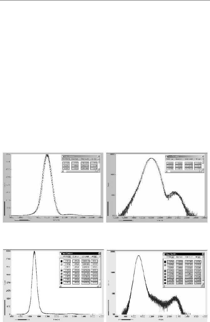
Fig. 7.33 IRF of an XP2020 PMT for count rates of 1 MHz, 100 kHz, 500 kHz in linea
r
scale (left) and logarithmic scale (right). The shift in M1 between 100 kHz and 1 MHz
count rate is 20 ps
Fig. 7.34 IRF of an H577320 photosensor module for count rates of 30 kHz, 300 kHz, an
d
4 MHz in linear scale (left) and logarithmic scale (right). The shift between 30 kHz an
d
4 MHz count rate is <2 ps and not discernible in the IRF curves
7.2 Optical Systems 297
count rate was changed by absorptive neutral-density filters. To keep the effective
optical path length constant, filters were replaced only by filters of equal thickness.
The XP2020 is used in large numbers in nuclear instrumentation and is still
something like a reference standard for high-current short-time PMTs. In spite of
its high voltage divider current, the XP2020 has a large timing shift per count rate
change. The first moment, M1, of the IRF shifts by about 20 ps when the count
rate changes from 100 kHz to 1 MHz. Compared to the XP 2020, the H5773 mod-
ule has an almost undetectable timing shift. The shift in the first moment of the
IRF between 30 kHz and 4 MHz count rate is <2 ps and not discernible in the IRF
curves. The high timing stability is most likely a result of the Cockroft-Walton
voltage-divider design of the H5773 modules [213].
It is often believed that MCP PMTs are unable to deliver count rates higher
than a few 10
4
photons per second without extreme changes in the IRF. There is
indeed a considerable change in the IRF if the light is focused into a small spot of
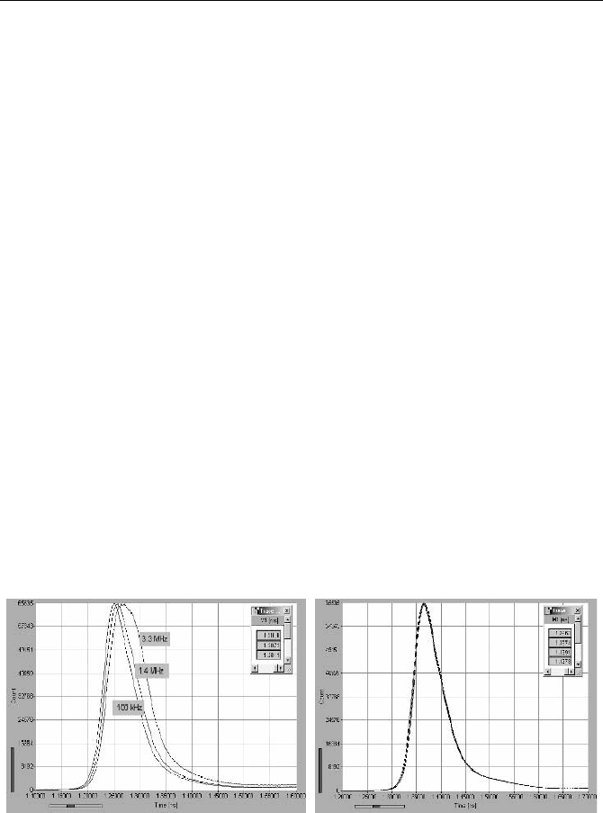
the photocathode. Figure 7.35, left, shows the IRF of a Hamamatsu R3809U MCP
for count rates of 100 kHz, 1.4 MHz, and 3.3 MHz for an illuminated spot of
2
u 5 mm. The test light source was a BHL600 diode laser of 40 ps pulse width.
There is a considerable change in the response, with a shift of almost 20 ps in the
first moment.
The strong dependence of the IRF on the spot size is certainly an effect of the
saturation of the microchannels. At high detector gain the output of a single mi-
crochannel saturates when an electron enters the input [297]. The recovery time of
the channel is in the microsecond range. If a large number of photoelectrons is
concentrated on a limited number of microchannels, the microchannels do not
fully recover and the IRF changes. A simple extrapolation from the spot area of
10 mm
2
in Fig. 7.35, left, to smaller areas shows that the useful count rate can
indeed be in the 10-kHz range.
Fig. 7.35 IRF of an R3809U MCP-PMT for different count rates. Illumination by diode
laser, pulse width 50 ps. Operating voltage –3 kV, 20 dB preamplifier gain, CFD threshold
80 mV. Left: Illuminated spot of 2 u 5 mm, recorded count rates 100 kHz , 1.4 MHz,
3.3 MHz. Right: Full cathode area illuminated, recorded count rates 3.3 MHz, 1.8 MHz,
480 kHz , and 25 kHz

298 7 Practice of TCSPC Experiments
However, if the full cathode area of 11 mm diameter is illuminated, the re-
sponse remains stable up to more than a 3 MHz recorded count rate, with a shift in
the first moment of less than 3 ps. The response curves are shown in Fig. 7.35,
right.
Table 7.2.
PMT
Type
Operating Voltage
(Gain Control
Voltage)
Voltage
Divider
Current
Count Rate
MHz
(recorded)
IRF
width
Shift
of M1
peak-peak
Amplitude-
Phase-Cross-
talk at 100 MHz
XP2020
2.5 kV
4 mA 0.1 to 1 230 ps 20 0.72°
R5600
0.9 kV
1 mA 0.03 to 4 175 ps 5 ps 0.18°
H7422 (0.78 V) N.A. 0.03 to 4 300 ps 8 ps 0.29°
H5773/83 (0.9 V) N.A. 0.03 to 4 175 ps <2 ps 0.072°
R3809U
3 kV
75 µA 0.03 to 3.3 30 ps <3 ps 0.11°
These results show that MCP PMTs can be used for count rates up to the maxi-
mum useful count rate of currently available TCSPC systems. It should be noted,
however, that at a count rate of 3.3 MHz and an operating voltage of 3 kV the
output current is considerably higher than the specified maximum of 100 nA. This
is certainly not a problem in applications where high count rates appear only tem-
porarily, e.g. in scanning microscopy. The lifetime of the MCP is not known at a
continuous count rate of more than 3 MHz.
The count-rate-dependent shift of the first moment found for some typical de-
tectors is summarised in the table 7.2. For comparison, in the last column the shift
of M1 was converted into the equivalent „amplitude-phase-crosstalk“ of a fre-
quency-domain instrument.
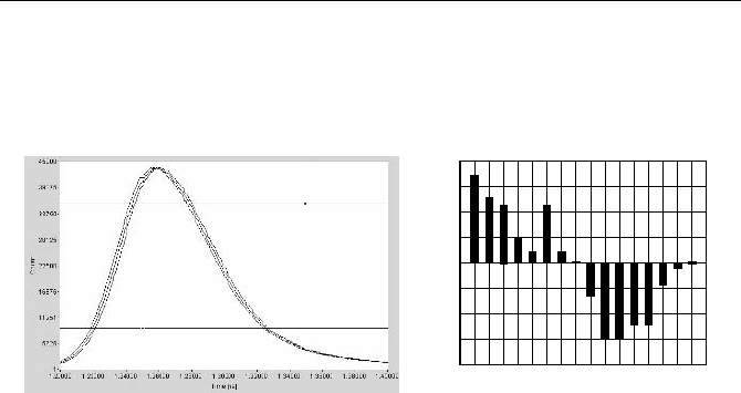
The IRF stability of a TCSPC system over time is shown in Fig. 7.36 and
Fig. 7.37. The test system was the same as for the count rate dependence, i.e. a
BHL
600, 650 nm, 40 ps diode laser and an SPC140 module. After a 30-minute
warmup, a series of 16 IRF curves was recorded over 16 minutes. Figure 7.36
shows the results for an H5773
20 module. The count rate was 250 kHz.
1
-2.0
-1.5
-0.5
0
0.5
1.0
1.5
2.0
-1.0
2345678910111213141516
Time (min)
IRF
drift
(ps)
Fig. 7.36 Series of IRF recordings for an H577320 (left) and drift of the first moment
(right). 16 consecutive recordings of 45 s over 16 minutes, time scale 100 ps/div
7.2 Optical Systems 299
The drift is so small that it is not discernible in the IRF curves. The drift of the
first moment of the IRF recordings is within
r 0.7 ps. Surprisingly, the timing
stability obtained with an R3809U MCP PMT is worse by about a factor of two.
The results are shown in Fig. 7.37.
1
-2.0
-1.5
-0.5
0
0.5
1.0
1.5
2.0
-1.0
2 3 4 5 6 7 8 9 10 11 12 13 14 15 16
Time (min)
IRF
drift
(ps)
Fig. 7.37 Series of IRF recordings for an R3809U (left) and drift of the first moment
(right). 16 consecutive recordings of 45 s over 16 minutes, time scale 20 ps/div. Please note
the different time scale compared to Fig. 7.36
The drift in the first moment is about r 1.5 ps, i.e. about twice as large as for the
H5773. The reason is certainly not the MCP itself. Instability in the high voltage is
also unlikely to cause the drift. At the operating voltage of 3 kV a change of 30 V in
voltage would be required for a shift of 3 ps. The most likely reason that the R3809
does not reach the stability of the H5773 is the lower gain. Slight changes in the
CFD offset in the TCSPC module have therefore a larger influence on timing.
7.2.14 PMT Voltage Dividers
In early TCSPC publications, a number of tips were given on how to optimise a
PMT voltage divider to obtain best time resolution. Suggestions for improving the
time resolution included adjustable voltage distributions at the dynodes and focus-
ing electrodes and even magnetic fields. Now the fastest detectors are MCP PMTs
and small photosensor modules, and nothing in these detectors can be adjusted.
Nevertheless, if you have to build or use a PMT with a conventional voltage di-
vider, you should keep some essential points in mind.
If the PMT has focusing electrodes, the voltage at these electrodes must be ad-
justed to obtain the best timing performance. The adjustment depends on the size
and location of the illuminated cathode area and may therefore be different for
different optical configurations. Some examples for the XP2020 are given in
Fig. 6.49, page 255. The potentiometers are at a high voltage, and the usual pre-
cautions against electrical shock must be taken. The design of the PMT housing
should preclude leakage of light from the voltage divider into the PMT, so that the
adjustment can be done under any convenient illumination.
The data sheets of short-time PMTs often suggest different voltage dividers for
high gain and high output pulse current. Because TCSPC detects only single pho-
tons the voltage divider for high gain usually performs best. To provide a ground

300 7 Practice of TCSPC Experiments
return path for the signal, the voltage divider resistors must be bypassed by capaci-
tors. For TCSPC, capacitors of a few nF are sufficient, and at the first dynodes the
capacitors can be smaller or even completely omitted. The capacitors should be
low-inductance ceramic types, located as close to the tube as possible.
The width of the transit time spread is proportional to the reciprocal square root
of the voltage between the cathode and the first dynode. Increasing this voltage
improves the IRF noticeably. It is, however, unknown how far the voltage can be
increased without dielectric breakdown in the tube or the socket.
The usual way of operating a PMT is with the cathode at negative high voltage
and the anode at ground. PMTs are often coated with a conductive layer. This
layer is connected to the cathode, i.e. to high voltage. Enough space around the
tube must be left to avoid corona discharges between the coating and the housing.
It is sometimes suggested that PMTs should be operated with the cathode at
ground and the anode at high (positive) voltage. Because the cathode is at ground,
possible corona effects and electroluminescence are avoided. However, a capaci-
tor must be used to decouple the anode pulses from the high voltage. Possible
breakdown of this capacitor results in permanent danger of electrical shock.
Moreover, noise from the high-voltage power supply is transferred directly into
the anode signal. For these reasons, operating a PMT with the cathode grounded is
not recommended for TCSPC.
The voltage divider can dissipate a considerable amount of heat. The heat
should be kept away from the tube in order to keep the dark count rate low. In
addition, good electrical shielding of the tube and the voltage divider is essential
to obtain a good time resolution, see Sect. 7.5.4, page 311.
7.2.15 Preamplifiers
The commonly used MCPs and PMTs deliver single-electron pulses of 20 to
50 mV when operated at maximum gain. Although these pulses can be detected by
the input discriminators of most TCSPC modules, a preamplifier is recommended
for several reasons. The most obvious one is that a good preamplifier, if it is con-
nected close to the detector output, improves the noise immunity of the system.
Moreover, with the amplifier the CFD can be operated at a higher discriminator
threshold, which improves the timing and the threshold stability.
The gain of the preamplifier allows the PMT to be operated at a correspond-
ingly lower gain. The reduction of the average output current at a given count rate
improves the timing stability and increases the lifetime of MCP PMTs.
Preamplifiers also protect the CFD against possible high-amplitude pulses.
PMTs are able to deliver output pulses of several hundred mA and a risetime of the
order of 1 ns, caused by cosmic ray particles, by radioactive decay, or by a simple
operator error. Potentially dangerous pulses can also occur if cables with unreliable
contacts are used. A cable at the output of a PMT can be charged to several hundred
Volts and then be discharged into the electronics to which it is connected, usually
destroying them. It is far cheaper to replace a preamplifier than a CFD.
The strongest argument is that a properly designed preamplifier can be used to
protect the detector against overload. The principle is shown in Fig. 7.38.
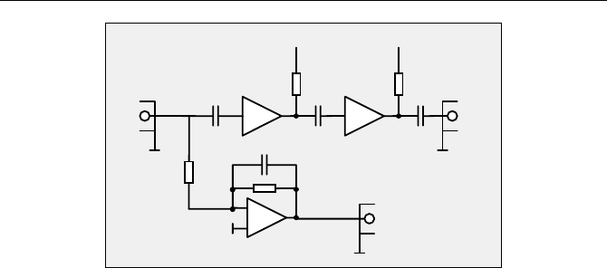
7.2 Optical Systems 301
+
-
AMP1
AMP3
Vcc
IN OUT
Overload
+9 .. +12V
R1
R2
C1 C2
C3
AMP2
Vcc
+9 .. +12V
C2
100k ... 10M
1n
1k
1n 1n 1n
R3 R4
220 220
MSA386MSA386
AD820
Fig. 7.38 Preamplifier with overload signal output
AMP1 and AMP2 are high-frequency amplifiers as they are used in communi-
cation devices. Two AC-coupled amplifiers are used in series to avoid signal in-
version. Many types of amplifier chips are available, with similar designs but
different gains and bandwidths. Depending on the amplifier chips used, AMP1
and AMP2 deliver a total gain between 12 dB and 40 dB, at a bandwidth between
500 MHz and several GHz. The DC component of the detector current is fed into
AMP3. AMP3 is an operational amplifier with FET input. It converts the input
current into a voltage with a transimpedance determined by R2. The output volt-
age of AMP 3 is proportional to the detector current. If it becomes too high it
activates an overload warning, e.g. turns on a LED or an acoustic signal, or
switches off the detector.
The preamplifier shown in Fig. 7.38 is a much better overload indicator than a
rate meter. Monitoring the count rate is not safe because the discriminator thresh-
old can be wrong, or the detector gain may be set too low to obtain any counts.
Moreover, the count rate may break down at extreme overload. An inexperienced
user may then increase the light intensity even more. In contrast, overload detec-
tion via the detector current responds properly in all these situations.
At first glance it may appear necessary to build an amplifier fast enough so that
it does not broaden the detector pulses. This would require about 1 GHz for con-
ventional PMTs and more than 3 GHz for MCPs. However, in practice the signal
bandwidth is limited by the discriminators in the CFD as well. The input band-
width of the discriminators is usually of the order of 1 GHz, so that an amplifier
bandwidth above 1 to 2 GHz does not improve the timing performance noticeably.
More important than extreme bandwidth are linearity and low noise, especially
low noise pickup from the environment (see Sect. 7.5.4, page 311). A good pre-
amplifier should amplify the detector pulses without noticeable nonlinearity up to
the maximum CFD threshold of the TCSPC module, i.e. about 500 mV. This is no
problem for the amplifiers used in the circuit shown in Fig. 7.38.
Figure 7.39 shows a TCSPC recording of a 45-ps diode-laser pulse. An
R3809U MCP PMT was used with a 20 dB, 1.6 GHz amplifier (left) and a 40 dB,
500 MHz amplifier. The operating voltages of the MCP were –3 kV and –2.7 kV,
respectively.
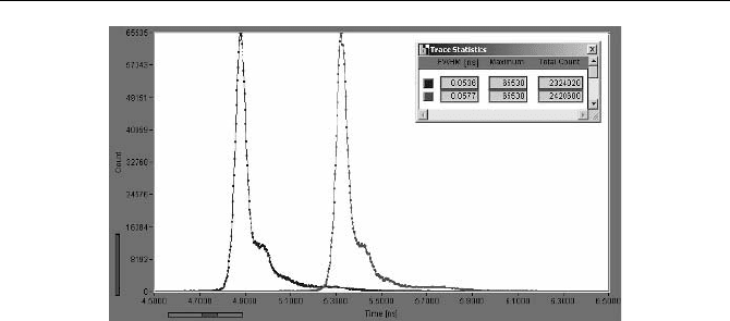
302 7 Practice of TCSPC Experiments
Fig. 7.39 TCSC Response of an R3809U50 MCP-PMT to a 45 ps diode laser pulse at
650 nm. Left: Preamplifier 20 dB, 1.6 GHz, MCP voltage 3 kV. Right: Preamplifier 42 dB,
500 MHz, MCP voltage 2.7 kV. The width of the recorded pulse is 54 ps and 58 ps, respec-
tively
The recorded pulse width was 54 and 58 ps, the calculated IRF width of the de-
tection system (without the laser) 30 ps and 36 ps. Although the bandwidth of the
40 dB amplifier was considerably smaller, the IRF width increased only slightly.
The increase can be explained by the smaller photon pulse amplitude at the lower
MCP voltage and the correspondingly lower signal-to-noise ratio. It is an accept-
able tradeoff for the higher count rate that can be obtained at the lower MCP sup-
ply voltage (see Fig. 6.31).
7.3 Detector Control and Overload Protection
PMTs and MCPs can easily be damaged or destroyed by overload. Even when an
MCP or PMT is switched off, if the cathode is exposed to a high light intensity the
cathode performance is temporarily impaired [297]; see also Fig. 6.19, page 233.
Detector protection is therefore an important issue in photon counting instrumen-
tation. In simple lifetime spectrometers, the problem can be solved by mechanical
flaps or switches that close the detection light path or switch off the detector when
the sample compartment is opened. But even then the detector can be damaged by
turning up the excitation power too high.
Microscopy applications have an extremely high risk of detector damage. A
microscope usually contains a strong mercury, xenon or halogen lamp that is used
for visual inspection of the sample. Because the lamp may shine into the TCSPC
detection path it is a potential source of detector damage, and a simple operator
error can destroy one or several detectors. Even daylight leaking through the sam-
ple into the detection path can cause detector overload. The problem is particularly
severe in two-photon microscopes with nondescanned detection. Detector over-
load protection is mandatory for these systems. A suitable protecting system is
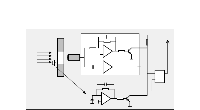
7.3 Detector Control and Overload Protection 303
shown in Fig. 7.40. The system does not require any control signal from the opti-
cal system and is therefore applicable to a wide range of instruments.
-
+
10p
1G
1k
/ovld
Photodiode
in front of
shutter
Shutter
Detector
Photodiode
light path
-
+
1k
/ovld
20dB
1.6 GHz
Photon pulses
to TCSPC module
/s
reset
/r
Q
shutter
Close
1k
OVLD
shutdown
detector
by
Operator
+5V
Preamplifier
Flip-Flop
and
Fig. 7.40 Principle of detector overload protection
The detector is placed behind a shutter. The detector output signal is connected
to a preamplifier as described in Fig. 7.38. If the safe output current of the detector
is exceeded the preamplifier delivers an overload signal, /ovld. The overload sig-
nal sets an overload flip-flop that closes the shutter.
A photodiode in front of the shutter delivers a second overload signal. Thus the
overload flip-flop cannot be reset as long as a potential overload situation persists.
Of course, the photodiode is far less sensitive than a PMT and therefore not able to
detect moderate overload. It does, however, detect a severe overload situation in
which even a short opening of the shutter could damage the detector.
The setup gives a reasonable safety against detector damage. However, it must be
noted that it does not give absolute safety. If a microscope lamp is switched on
when the shutter is open and the detector is active there is a delay of some milli-
seconds until the shutter closes. To avoid risk completely, another shutter must be
placed in front of the lamp and operated exclusively with the detector shutter.
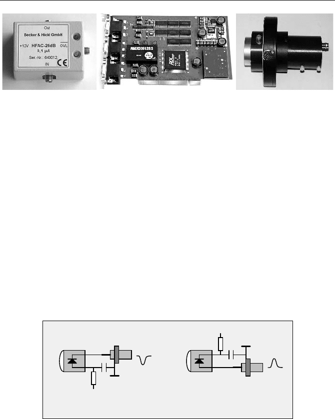
Commercially available components for detector protection and control are
shown in Fig. 7.41. The system uses a preamplifier with the design shown in
Fig. 7.38. The overload-shutdown flip-flops and the power switches for the shut-
ters are on a separate detector controller card. The card controls one or two detec-
tors. If a preamplifier indicates an overload the shutters are closed and the gain of
the corresponding detector is shut down. The controller card also provides soft-
ware control of the gain of one or two H5773, H5783 or H7422 photosensor mod-
ules, or of one or two high voltage power supplies. A driver for thermoelectric
coolers, e.g. for the H7422, is implemented as well.
304 7 Practice of TCSPC Experiments
Fig. 7.41 Components for detector overload protection: HFAC26 preamplifier, DCC100
detector controller card, and shutter assembly for R3809U MCP. Becker & Hickl, Berlin
A problem associated with shutters is often heat dissipation by the shutter coils.
If the shutter warms up the detector, the dark count rate may increase substan-
tially. Excessive power dissipation of the shutter coils can be avoided by reducing
the coil current. In practice a shutter needs to be operated at its full switching
current only in the moment when it opens. Some 100 ms later the current can be
decreased by 60 to 70%, so that the power consumption is substantially reduced.
7.4 Generating the Synchronisation Signal
TCSPC needs a timing reference signal from the light source. This is no problem
for picosecond diode lasers, which deliver a trigger output pulse from the laser
diode driver. For free-running solid-state lasers or jet-stream dye lasers, a suitable
synchronisation signal can be generated by a photodiode. A simple solution is to
use a fast PIN photodiode in one of the circuits shown in Fig. 7.42.
-12 to -30V
+12 to +30V
Positive OutputNegative Output
R
C
R
C
Connector
Connector
Photodiode Photodiode
1k
1k
10n
10n
Fig. 7.42 Photodiode for reference signal generation
The resistor, R, protects the diode against overload and accidental reversal of
the supply voltage. The capacitor, C, provides a low-impedance RF-return path to
ground. The capacitor must be a low-impedance surface-mount type. The resistor
is not critical. The connection length in the path GND-C-Photodiode-Connector
must be kept to a minimum, or a 50 Ohm strip line on a printed circuit board must
be used. Please note that the circuit gives a fast response only if the output is ter-
minated with 50 Ohm.
The requirements for the diode depend on the amplitude fluctuations and the in-
tensity drift of the laser. Good Ti:Sapphire lasers have negligible amplitude fluc-