Beer F.P., Johnston E.R., DeWolf J.T., Mazurek D.F. Mechanics of Materials
Подождите немного. Документ загружается.

Apago PDF Enhancer
147
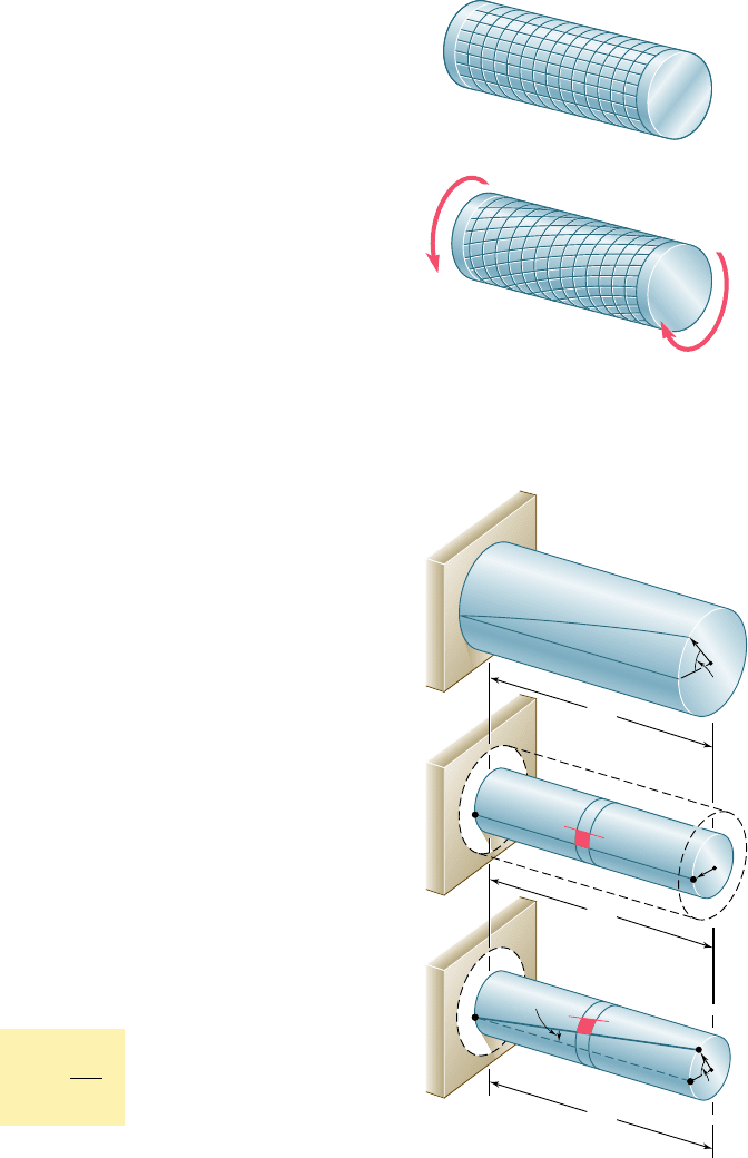
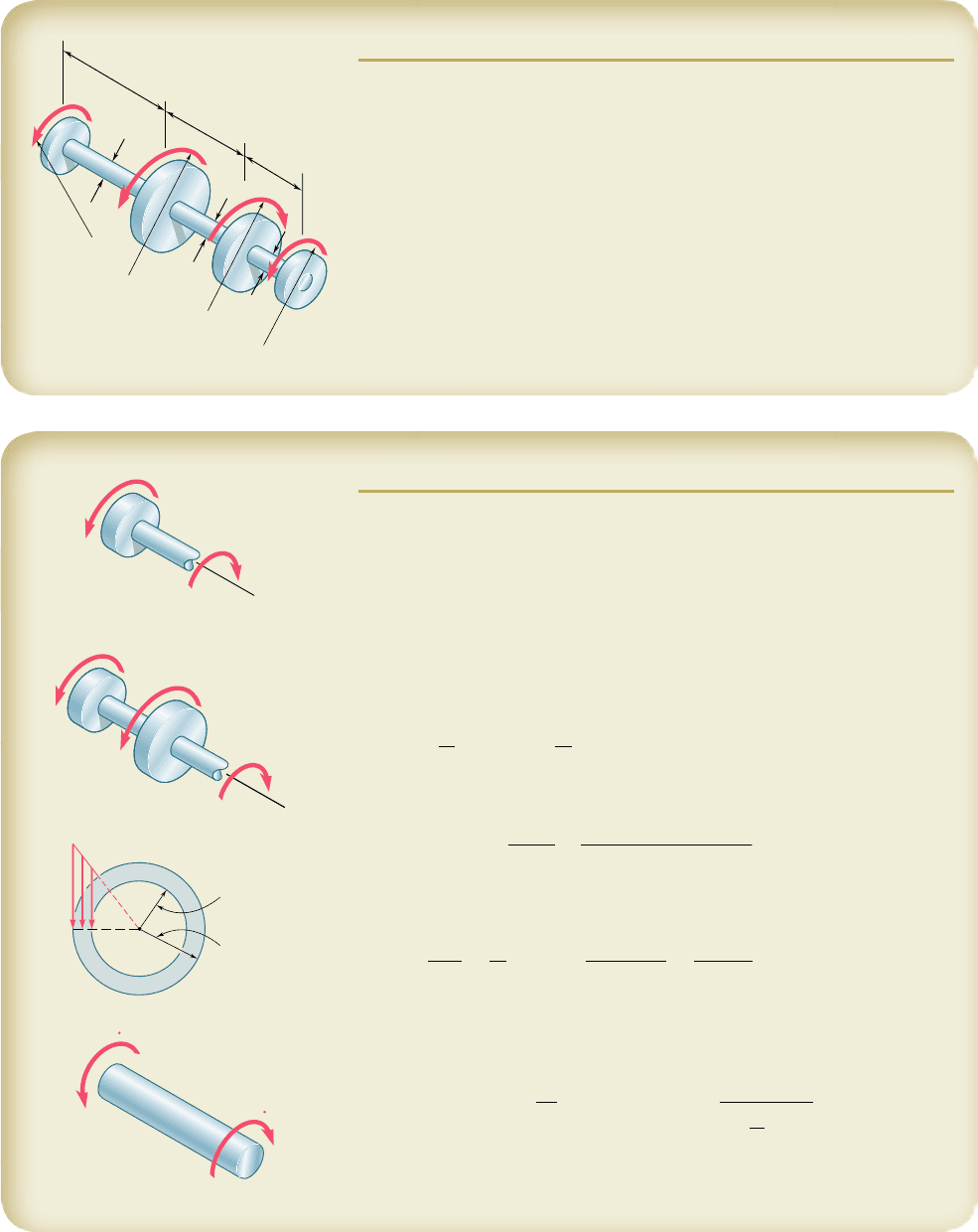
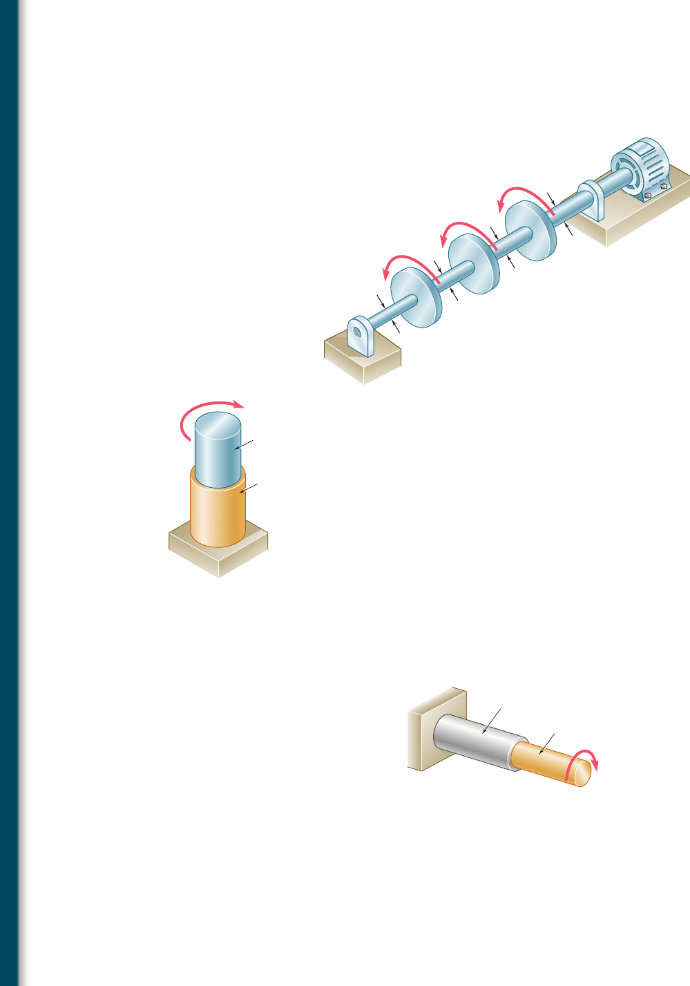
Our discussion so far has ignored the mode of application of the
twisting couples T and T9. If all sections of the shaft, from one end to
the other, are to remain plane and undistorted, we must make sure that
the couples are applied in such a way that the ends of the shaft them-
selves remain plane and undistorted. This may be accomplished by
applying the couples T and T9 to rigid plates, which are solidly attached
to the ends of the shaft (Fig. 3.12a). We can then be sure that all sec-
tions will remain plane and undistorted when the loading is applied,
and that the resulting deformations will occur in a uniform fashion
throughout the entire length of the shaft. All of the equally spaced cir-
cles shown in Fig. 3.12a will rotate by the same amount relative to their
neighbors, and each of the straight lines will be transformed into a curve
(helix) intersecting the various circles at the same angle (Fig. 3.12b).
The derivations given in this and the following sections will be
based on the assumption of rigid end plates. Loading conditions
encountered in practice may differ appreciably from those corre-
sponding to the model of Fig. 3.12. The chief merit of this model is
that it helps us define a torsion problem for which we can obtain an
exact solution, just as the rigid-end-plates model of Sec. 2.17 made
it possible for us to define an axial-load problem which could be
easily and accurately solved. By virtue of Saint-Venant’s principle, the
results obtained for our idealized model may be extended to most
engineering applications. However, we should keep these results
associated in our mind with the specific model shown in Fig. 3.12.
We will now determine the distribution of shearing strains in
a circular shaft of length L and radius c that has been twisted through
an angle f (Fig. 3.13a). Detaching from the shaft a cylinder of radius
r, we consider the small square element formed by two adjacent
circles and two adjacent straight lines traced on the surface of the
cylinder before any load is applied (Fig. 3.13b). As the shaft is
subjected to a torsional load, the element deforms into a rhombus
(Fig. 3.13c). We now recall from Sec. 2.14 that the shearing strain g
in a given element is measured by the change in the angles formed
by the sides of that element. Since the circles defining two of the
sides of the element considered here remain unchanged, the shear-
ing strain g must be equal to the angle between lines AB and A9B.
(We recall that g should be expressed in radians.)
We observe from Fig. 3.13c that, for small values of g, we can
express the arc length AA9 as AA9 5 Lg. But, on the other hand, we
have AA9 5 rf. It follows that Lg 5 rf, or
g 5
r
f
L
(3.2)
where g and f are both expressed in radians. The equation obtained
shows, as we could have anticipated, that the shearing strain g at a
given point of a shaft in torsion is proportional to the angle of twist
f. It also shows that g is proportional to the distance r from the axis
of the shaft to the point under consideration. Thus, the shearing
strain in a circular shaft varies linearly with the distance from the
axis of the shaft.
3.3 Deformations in a Circular Shaft
(b)
(a)
T'
T
Fig. 3.12 Deformation of shaft
subject to twisting couples.
L
L
(a)
(b)
(c)
L
B
O
c
␥
B
B
A
O
O
A'
A
Fig. 3.13 Shearing strain.
bee80288_ch03_140-219.indd Page 147 9/21/10 3:04:11 PM user-f499bee80288_ch03_140-219.indd Page 147 9/21/10 3:04:11 PM user-f499 /Users/user-f499/Desktop/Temp Work/Don't Delete Job/MHDQ251:Beer:201/ch03/Users/user-f499/Desktop/Temp Work/Don't Delete Job/MHDQ251:Beer:201/ch03

Apago PDF Enhancer
148
Torsion
It follows from Eq. (3.2) that the shearing strain is maximum
on the surface of the shaft, where r 5 c. We have
g
max
5
c
f
L
(3.3)
Eliminating f from Eqs. (3.2) and (3.3), we can express the shearing
strain g at a distance r from the axis of the shaft as
g 5
r
c
g
max
(3.4)
3.4 STRESSES IN THE ELASTIC RANGE
No particular stress-strain relationship has been assumed so far in our
discussion of circular shafts in torsion. Let us now consider the case
when the torque T is such that all shearing stresses in the shaft remain
below the yield strength t
Y
. We know from Chap. 2 that, for all practi-
cal purposes, this means that the stresses in the shaft will remain below
the proportional limit and below the elastic limit as well. Thus, Hooke’s
law will apply and there will be no permanent deformation.
Recalling Hooke’s law for shearing stress and strain from Sec.
2.14, we write
t 5 Gg (3.5)
where G is the modulus of rigidity or shear modulus of the material.
Multiplying both members of Eq. (3.4) by G, we write
Gg 5
r
c
Gg
max
or, making use of Eq. (3.5),
t 5
r
c
t
max
(3.6)
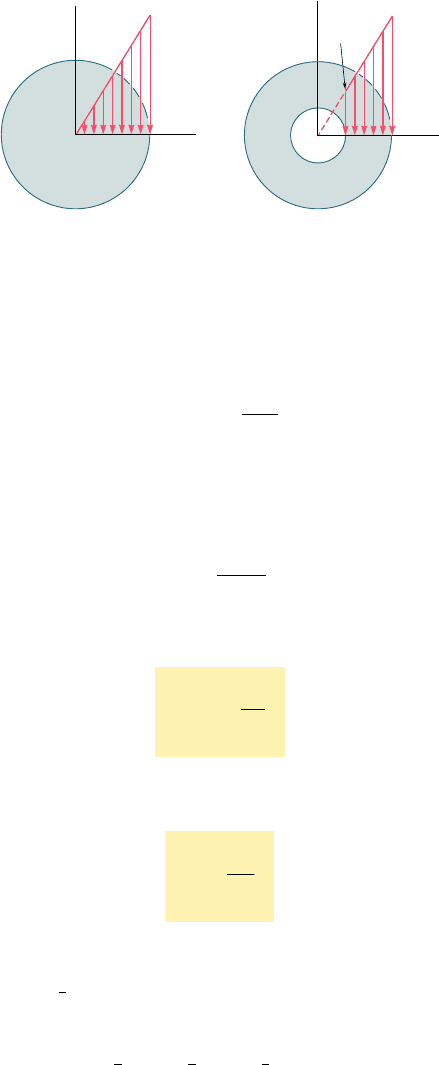
The equation obtained shows that, as long as the yield strength (or
proportional limit) is not exceeded in any part of a circular shaft, the
shearing stress in the shaft varies linearly with the distance r from
the axis of the shaft. Figure 3.14a shows the stress distribution in a
solid circular shaft of radius c, and Fig. 3.14b in a hollow circular
shaft of inner radius c
1
and outer radius c
2
. From Eq. (3.6), we find
that, in the latter case,
t
min
5
c
1
c
2
t
max
(3.7)
We now recall from Sec. 3.2 that the sum of the moments of
the elementary forces exerted on any cross section of the shaft must
be equal to the magnitude T of the torque exerted on the shaft:
er(t dA) 5 T (3.1)
bee80288_ch03_140-219.indd Page 148 9/21/10 3:04:16 PM user-f499bee80288_ch03_140-219.indd Page 148 9/21/10 3:04:16 PM user-f499 /Users/user-f499/Desktop/Temp Work/Don't Delete Job/MHDQ251:Beer:201/ch03/Users/user-f499/Desktop/Temp Work/Don't Delete Job/MHDQ251:Beer:201/ch03
Apago PDF Enhancer
149
Substituting for t from (3.6) into (3.1), we write
T 5
e
rt dA 5
t
max
c
e
r
2
dA
But the integral in the last member represents the polar moment of
inertia J of the cross section with respect to its center O. We have
therefore
T 5
t
max
J
c
(3.8)
or, solving for t
max
,
t
max
5
Tc
J
(3.9)
Substituting for t
max
from (3.9) into (3.6), we express the shearing
stress at any distance r from the axis of the shaft as
t 5
T
r
J
(3.10)
Equations (3.9) and (3.10) are known as the elastic torsion formulas.
We recall from statics that the polar moment of inertia of a circle of
radius c is
J
5
1
2
pc
4
. In the case of a hollow circular shaft of inner
radius c
1
and outer radius c
2
, the polar moment of inertia is
J 5
1
2
pc
2
4
2
1
2
pc
1
4
5
1
2
p 1c
2
4
2 c
4
1
2 (3.11)
We note that, if SI metric units are used in Eq. (3.9) or (3.10),
T will be expressed in N ? m, c or r in meters, and J in m
4
; we check
that the resulting shearing stress will be expressed in N/m
2
, that is,
pascals (Pa). If U.S. customary units are used, T should be expressed
in lb ? in., c or r in inches, and J in in
4
, with the resulting shearing
stress expressed in psi.
3.4 Stresses in the Elastic Range
max
max
min
(a)
(b)
c
O
c
1
c
2
O
Fig. 3.14 Distribution of shearing stresses.
bee80288_ch03_140-219.indd Page 149 9/21/10 3:04:17 PM user-f499bee80288_ch03_140-219.indd Page 149 9/21/10 3:04:17 PM user-f499 /Users/user-f499/Desktop/Temp Work/Don't Delete Job/MHDQ251:Beer:201/ch03/Users/user-f499/Desktop/Temp Work/Don't Delete Job/MHDQ251:Beer:201/ch03
Apago PDF Enhancer
150
EXAMPLE 3.01
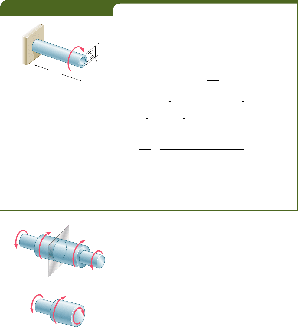
A hollow cylindrical steel shaft is 1.5 m long and has inner and outer
diameters respectively equal to 40 and 60 mm (Fig. 3.15). (a) What is the
largest torque that can be applied to the shaft if the shearing stress is not
to exceed 120 MPa? (b) What is the corresponding minimum value of the
shearing stress in the shaft?
(a) Largest Permissible Torque. The largest torque T that can
be applied to the shaft is the torque for which t
max
5 120 MPa. Since
this value is less than the yield strength for steel, we can use Eq. (3.9).
Solving this equation for T, we have
T 5
J
t
max
c
(3.12)
Recalling that the polar moment of inertia J of the cross section is given by
Eq. (3.11), where
c
1
5
1
2
1
40 mm
2
5 0.02 m and
c
2
5
1
2
1
60 mm
2
5 0.03 m,
we write
J
5
1
2
p 1c
4
2
2 c
4
1
25
1
2
p10.03
4
2 0.02
4
25 1.021 3 10
26
m
4
Substituting for J and t
max
into (3.12), and letting c 5 c
2
5 0.03 m, we
have
T 5
Jt
max
c
5
11.021 3 10
26
m
4
21120 3 10
6
Pa2
0.03 m
5 4.08 kN ? m
(b) Minimum Shearing Stress. The minimum value of the shear-
ing stress occurs on the inner surface of the shaft. It is obtained from Eq.
(3.7), which expresses that t
min
and t
max
are respectively proportional to
c
1
and c
2
:
t
min
5
c
1
c
2
t
max
5
0.02 m
0.03 m
1120 MPa25 80 MPa
1.5 m
40 mm
60 mm
T
Fig. 3.15
The torsion formulas (3.9) and (3.10) were derived for a shaft
of uniform circular cross section subjected to torques at its ends.
However, they can also be used for a shaft of variable cross section
or for a shaft subjected to torques at locations other than its ends
(Fig. 3.16a). The distribution of shearing stresses in a given cross
section S of the shaft is obtained from Eq. (3.9), where J denotes the
polar moment of inertia of that section, and where T represents the
internal torque in that section. The value of T is obtained by drawing
the free-body diagram of the portion of shaft located on one side of
the section (Fig. 3.16b) and writing that the sum of the torques
applied to that portion, including the internal torque T, is zero (see
Sample Prob. 3.1).
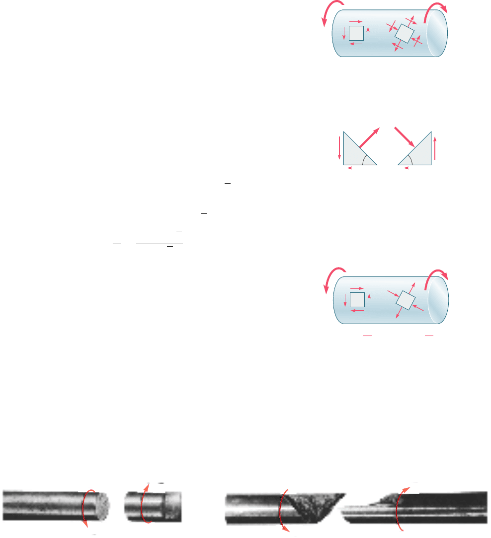
Up to this point, our analysis of stresses in a shaft has been
limited to shearing stresses. This is due to the fact that the element
we had selected was oriented in such a way that its faces were either
parallel or perpendicular to the axis of the shaft (Fig. 3.5). We know
from earlier discussions (Secs. 1.11 and 1.12) that normal stresses,
shearing stresses, or a combination of both may be found under the
same loading condition, depending upon the orientation of the
element that has been chosen. Consider the two elements a and
b located on the surface of a circular shaft subjected to torsion
B
(a)
(b)
T
C
T
E
T
B
T
A
E
B
S
C
A
S
E
T
T
B
T
E
Fig. 3.16 Shaft with variable cross
section.
bee80288_ch03_140-219.indd Page 150 11/2/10 12:48:16 AM user-f499bee80288_ch03_140-219.indd Page 150 11/2/10 12:48:16 AM user-f499 /Users/user-f499/Desktop/Temp Work/Don't Delete Job/MHDQ251:Beer:201/ch03/Users/user-f499/Desktop/Temp Work/Don't Delete Job/MHDQ251:Beer:201/ch03
Apago PDF Enhancer
151
(Fig. 3.17). Since the faces of element a are respectively parallel and
perpendicular to the axis of the shaft, the only stresses on the ele-
ment will be the shearing stresses defined by formula (3.9), namely
t
max
5 TcyJ. On the other hand, the faces of element b, which form
arbitrary angles with the axis of the shaft, will be subjected to a
combination of normal and shearing stresses.
Let us consider the stresses and resulting forces on faces that
are at 458 to the axis of the shaft. In order to determine the stresses
on the faces of this element, we consider the two triangular elements
shown in Fig. 3.18 and draw their free-body diagrams. In the case
of the element of Fig. 3.18a, we know that the stresses exerted on
the faces BC and BD are the shearing stresses t
max
5 TcyJ. The
magnitude of the corresponding shearing forces is thus t
max
A
0
, where
A
0
denotes the area of the face. Observing that the components along
DC of the two shearing forces are equal and opposite, we conclude
that the force F exerted on DC must be perpendicular to that face.
It is a tensile force, and its magnitude is
F 5 21t
max
A
0
2cos 45° 5 t
max
A
0
12 (3.13)
The corresponding stress is obtained by dividing the force F by the
area A of face DC. Observing that A 5 A
0
12, we write
s 5
F
A
5
t
max
A
0
12
A
0
12
5 t
max
(3.14)
A similar analysis of the element of Fig. 3.18b shows that the stress
on the face BE is s 5 2t
max
. We conclude that the stresses exerted
on the faces of an element c at 458 to the axis of the shaft (Fig. 3.19)
are normal stresses equal to 6t
max
. Thus, while the element a in
Fig. 3.19 is in pure shear, the element c in the same figure is sub-
jected to a tensile stress on two of its faces, and to a compressive
stress on the other two. We also note that all the stresses involved
have the same magnitude, TcyJ.†
As you learned in Sec. 2.3, ductile materials generally fail in
shear. Therefore, when subjected to torsion, a specimen J made of
a ductile material breaks along a plane perpendicular to its longitu-
dinal axis (Photo 3.2a). On the other hand, brittle materials are
weaker in tension than in shear. Thus, when subjected to torsion, a
specimen made of a brittle material tends to break along surfaces
that are perpendicular to the direction in which tension is maximum,
i.e., along surfaces forming a 458 angle with the longitudinal axis of
the specimen (Photo 3.2b).
3.4 Stresses in the Elastic Range
†Stresses on elements of arbitrary orientation, such as element b of Fig. 3.18, will be dis-
cussed in Chap. 7.
Photo 3.2 Shear failure of shaft subject to torque.
(
a
)
Ducti
l
e
f
ai
l
ure
T'
T
(
b
)
Britt
l
e
f
ai
l
ur
e
T'
T
a
max
T
T'
b
Fig. 3.17 Circular shaft with
elements at different orientations.
(a)(b)
CCBB
D
E
max
A
0
max
A
0
max
A
0
max
A
0
45⬚
45⬚
FF'
Fig. 3.18 Forces on faces at 458 to
shaft axis.
⫽
Tc
J
max
⫽⫾
Tc
J
45⬚
a
T
T'
c
Fig. 3.19 Shaft with elements with
only shear stresses or normal stresses.
bee80288_ch03_140-219.indd Page 151 9/21/10 3:04:24 PM user-f499bee80288_ch03_140-219.indd Page 151 9/21/10 3:04:24 PM user-f499 /Users/user-f499/Desktop/Temp Work/Don't Delete Job/MHDQ251:Beer:201/ch03/Users/user-f499/Desktop/Temp Work/Don't Delete Job/MHDQ251:Beer:201/ch03
Apago PDF Enhancer
152
SAMPLE PROBLEM 3.1
Shaft BC is hollow with inner and outer diameters of 90 mm and 120 mm,
respectively. Shafts AB and CD are solid and of diameter d. For the loading
shown, determine (a) the maximum and minimum shearing stress in shaft
BC, (b) the required diameter d of shafts AB and CD if the allowable shear-
ing stress in these shafts is 65 MPa.
0.9 m
d
A
B
T
C
T
D
0.7 m
0.5 m
120 mm
d
C
D
T
A
6 kN · m
14 kN · m
26 kN · m
6 kN · m
T
B
SOLUTION
Equations of Statics. Denoting by T
AB
the torque in shaft AB, we
pass a section through shaft AB and, for the free body shown, we write
©M
x
5 0:
1
6 kN ? m
2
2 T
AB
5 0T
AB
5 6 kN ? m
We now pass a section through shaft BC and, for the free body shown, we
have
©M
x
5 0:
1
6 kN ? m
2
1
1
14 kN ? m
2
2 T
BC
5 0T
BC
5 20 kN ? m
a. Shaft BC. For this hollow shaft we have
J 5
p
2
1c
4
2
2 c
4
1
25
p
2
310.0602
4
2 10.0452
4
45 13.92 3 10
26
m
4
Maximum Shearing Stress. On the outer surface, we have
t
max
5 t
2
5
T
BC
c
2
J
5
1
20 kN ? m
2
1
0.060 m
2
13.92 3 10
26
m
4
t
max
5 86.2 MPab
Minimum Shearing Stress. We write that the stresses are propor-
tional to the distance from the axis of the shaft.
t
min
t
max
5
c
1
c
2
t
min
86.2 MPa
5
45 mm
60 mm
t
m
i
n
5 64.7 MPab
b. Shafts AB and CD. We note that in both of these shafts the mag-
nitude of the torque is T 5 6 kN ? m and t
all
5 65 MPa. Denoting by c
the radius of the shafts, we write
t 5
Tc
J
65 MPa 5
1
6 kN ? m
2
c
p
2
c
4
c
3
5 58
.
8 3 10
26
m
3
c
5 38
.
9 3 10
23
m
d
5 2c 5 2138.9 mm2
d
5 77
.
8 mmb
A
T
AB
x
T
A
6 kN · m
T
B
A
B
T
BC
xx
T
A
6 kN · m
14 kN · m
c
1
45 mm
c
2
60 mm
2
1
A
B
6 kN · m
6 kN ·
m
bee80288_ch03_140-219.indd Page 152 9/21/10 3:04:31 PM user-f499bee80288_ch03_140-219.indd Page 152 9/21/10 3:04:31 PM user-f499 /Users/user-f499/Desktop/Temp Work/Don't Delete Job/MHDQ251:Beer:201/ch03/Users/user-f499/Desktop/Temp Work/Don't Delete Job/MHDQ251:Beer:201/ch03
Apago PDF Enhancer
153
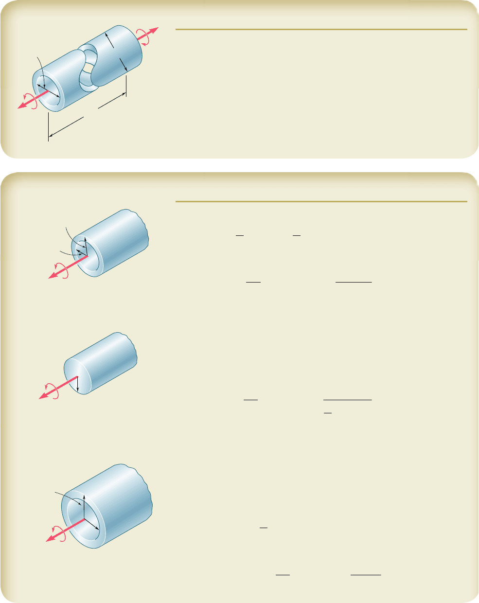
SAMPLE PROBLEM 3.2
The preliminary design of a large shaft connecting a motor to a generator
calls for the use of a hollow shaft with inner and outer diameters of 4 in.
and 6 in., respectively. Knowing that the allowable shearing stress is 12 ksi,
determine the maximum torque that can be transmitted (a) by the shaft as
designed, (b) by a solid shaft of the same weight, (c) by a hollow shaft of
the same weight and of 8-in. outer diameter.
8 ft
T'
T
6 in.
4 in.
SOLUTION
a. Hollow Shaft as Designed. For the hollow shaft we have
J 5
p
2
1c
4
2
2 c
4
1
25
p
2
313 in.2
4
2 12 in.2
4
45 102.1 in
4
Using Eq. (3.9), we write
t
max
5
Tc
2
J
12 ksi 5
T13 in.
2
102.1 in
4
T 5 408
k
ip ? in.b
b. Solid Shaft of Equal Weight. For the shaft as designed and this
solid shaft to have the same weight and length, their cross-sectional areas
must be equal.
A
1a2
5 A
1b2
p 313 in.2
2
2 12 in.2
2
45 pc
2
3
c
3
5 2.24 in.
Since t
all
5 12 ksi, we write
t
max
5
Tc
3
J
12 ksi 5
T12.24 in.2
p
2
12.24 in.2
4
T 5 211
k
ip ? in.b
c. Hollow Shaft of 8-in. Diameter. For equal weight, the cross-
sectional areas again must be equal. We determine the inside diameter of
the shaft by writing
A
1a2
5 A
1c2
p 313 in.2
2
2 12 in.2
2
45 p 314 in.2
2
2 c
2
5
4
c
5
5 3.317 in.
For c
5
5 3.317 in. and c
4
5 4 in.,
J 5
p
2
314 in.2
4
2 13.317 in.2
4
45 212 in
4
With t
all
5 12 ksi and c
4
5 4 in.,
t
max
5
Tc
4
J
12 ksi 5
T14 in.
2
212 in
4
T 5 636
k
ip ? in.b
c
2
⫽ 3 in.
c
1
⫽ 2 in.
T
c
3
T
c
4
⫽ 4 in.
c
5
T
bee80288_ch03_140-219.indd Page 153 9/21/10 9:15:26 PM user-f499bee80288_ch03_140-219.indd Page 153 9/21/10 9:15:26 PM user-f499 /Users/user-f499/Desktop/Temp Work/Don't Delete Job/MHDQ251:Beer:201/ch03/Users/user-f499/Desktop/Temp Work/Don't Delete Job/MHDQ251:Beer:201/ch03
Apago PDF Enhancer
PROBLEMS
154
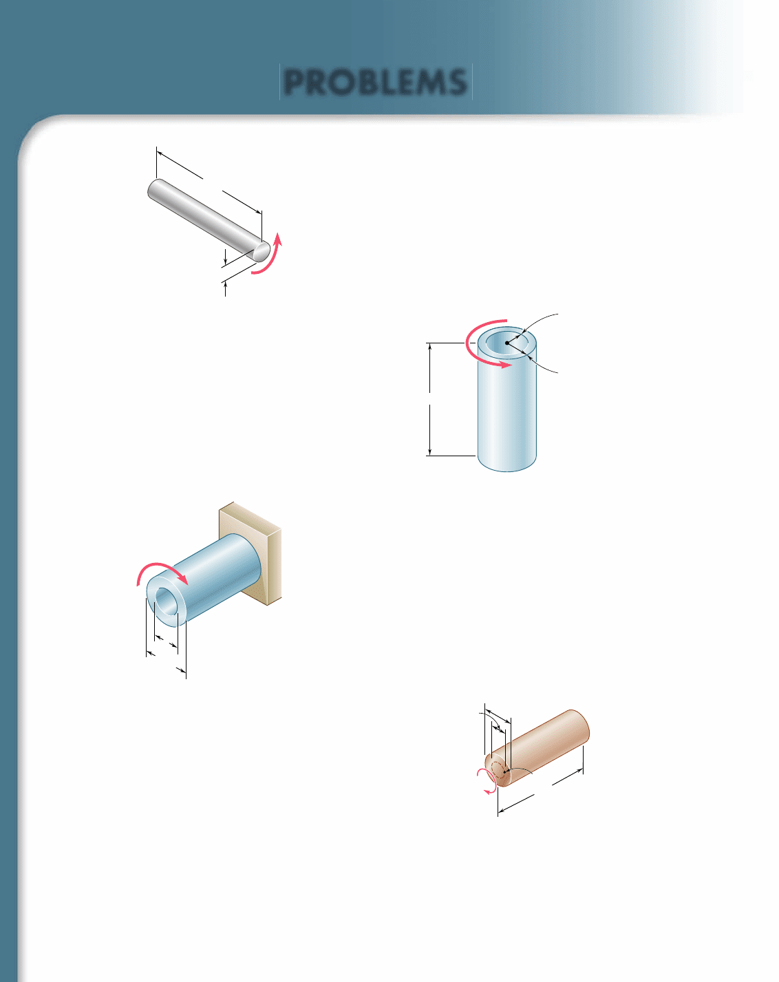
3.1 (a) Determine the maximum shearing stress caused by a 4.6-kN ? m
torque T in the 76-mm-diameter solid aluminum shaft shown.
(b) Solve part a, assuming that the solid shaft has been replaced by
a hollow shaft of the same outer diameter and of 24-mm inner
diameter.
3.2 (a) Determine the torque T that causes a maximum shearing stress
of 45 MPa in the hollow cylindrical steel shaft shown. (b) Deter-
mine the maximum shearing stress caused by the same torque T
in a solid cylindrical shaft of the same cross-sectional area.
76 mm
1.2 m
T
Fig. P3.1
3.3 Knowing that d 5 1.2 in., determine the torque T that causes a
maximum shearing stress of 7.5 ksi in the hollow shaft shown.
3.4 Knowing that the internal diameter of the hollow shaft shown is
d 5 0.9 in., determine the maximum shearing stress caused by a
torque of magnitude T 5 9 kip ? in.
3.5 A torque T 5 3 kN ? m is applied to the solid bronze cylinder
shown. Determine (a) the maximum shearing stress, (b) the shear-
ing stress at point D, which lies on a 15-mm-radius circle drawn
on the end of the cylinder, (c) the percent of the torque carried
by the portion of the cylinder within the 15-mm radius.
2.4 m
30 mm
45 mm
T
Fig. P3.2
d
1.6 in.
T
Fig. P3.3 and P3.4
60 mm
30 mm
D
200 mm
T 3 kN · m
Fig. P3.5
3.6 (a) Determine the torque that can be applied to a solid shaft of
20-mm diameter without exceeding an allowable shearing stress of
80 MPa. (b) Solve part a, assuming that the solid shaft has been
replaced by a hollow shaft of the same cross-sectional area and with
an inner diameter equal to half of its outer diameter.
bee80288_ch03_140-219.indd Page 154 9/21/10 3:04:51 PM user-f499bee80288_ch03_140-219.indd Page 154 9/21/10 3:04:51 PM user-f499 /Users/user-f499/Desktop/Temp Work/Don't Delete Job/MHDQ251:Beer:201/ch03/Users/user-f499/Desktop/Temp Work/Don't Delete Job/MHDQ251:Beer:201/ch03
Apago PDF Enhancer
155
Problems
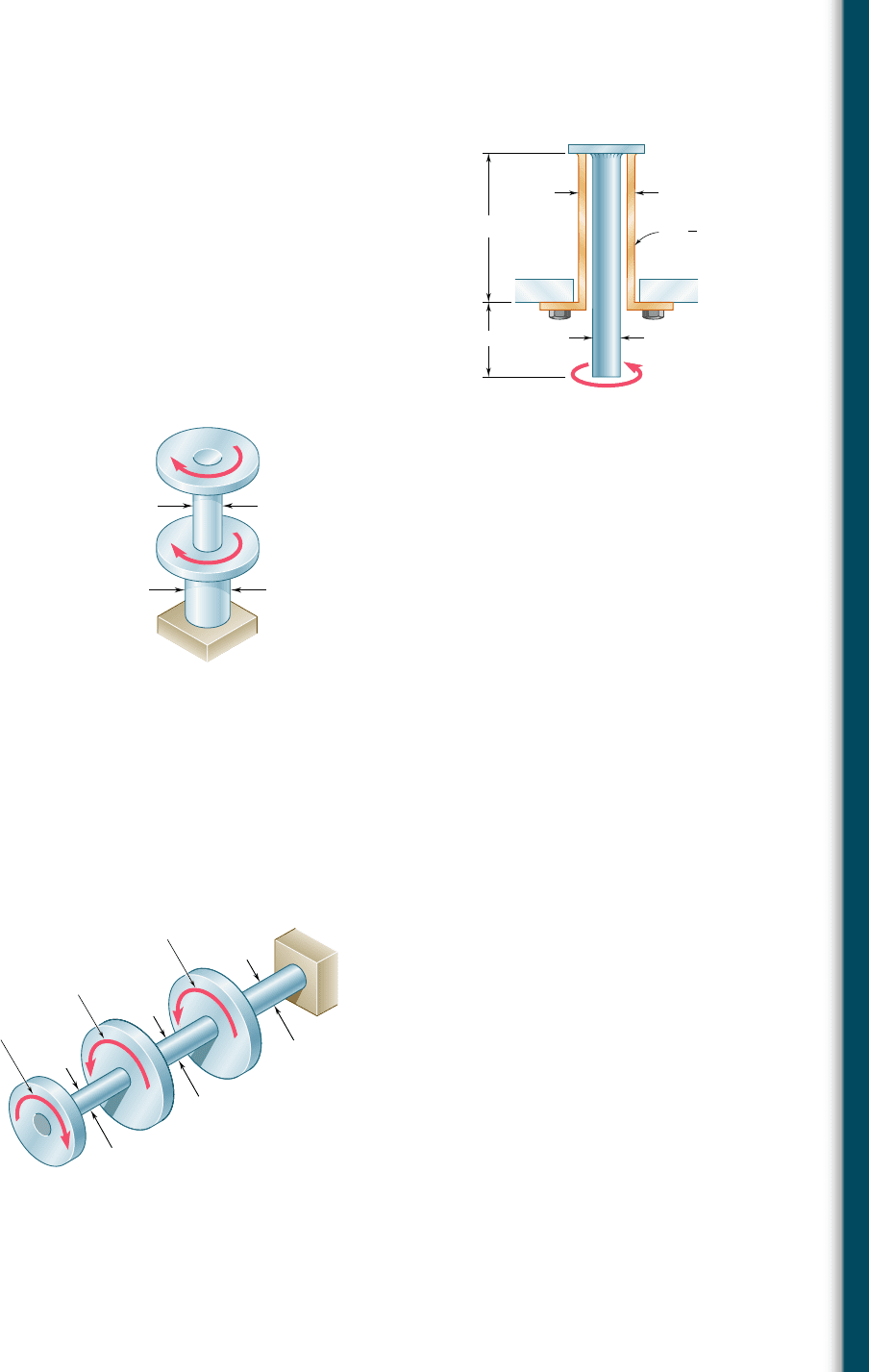
3.7 The solid spindle AB has a diameter d
s
5 1.5 in. and is made of
a steel with an allowable shearing stress of 12 ksi, while sleeve CD
is made of a brass with an allowable shearing stress of 7 ksi. Deter-
mine the largest torque T that can be applied at A.
3.8 The solid spindle AB is made of a steel with an allowable shearing
stress of 12 ksi, and sleeve CD is made of a brass with an allowable
shearing stress of 7 ksi. Determine (a) the largest torque T that
can be applied at A if the allowable shearing stress is not to be
exceeded in sleeve CD, (b) the corresponding required value of
the diameter d
s
of spindle AB.
3.9 The torques shown are exerted on pulleys A and B. Knowing that
both shafts are solid, determine the maximum shearing stress in
(a) in shaft AB, (b) in shaft BC.
4 in.
8 in.
d
s
t
in.
1
4
3 in.
D
C
A
B
T
Fig. P3.7 and P3.8
30 mm
46 mm
C
A
B
T
A
300 N · m
T
B
400 N · m
Fig. P3.9
3.10 In order to reduce the total mass of the assembly of Prob. 3.9, a
new design is being considered in which the diameter of shaft BC
will be smaller. Determine the smallest diameter of shaft BC for
which the maximum value of the shearing stress in the assembly
will not increase.
3.11 Knowing that each of the shafts AB, BC, and CD consists of a solid
circular rod, determine (a) the shaft in which the maximum shear-
ing stress occurs, (b) the magnitude of that stress.
D
d
CD
21 mm
B
d
BC
18 mm
C
60 N · m
48 N · m
A
d
AB
15 mm
144 N · m
Fig. P3.11 and P3.12
3.12 Knowing that an 8-mm-diameter hole has been drilled through each
of the shafts AB, BC, and CD, determine (a) the shaft in which the
maximum shearing stress occurs, (b) the magnitude of that stress.
bee80288_ch03_140-219.indd Page 155 9/21/10 3:05:08 PM user-f499bee80288_ch03_140-219.indd Page 155 9/21/10 3:05:08 PM user-f499 /Users/user-f499/Desktop/Temp Work/Don't Delete Job/MHDQ251:Beer:201/ch03/Users/user-f499/Desktop/Temp Work/Don't Delete Job/MHDQ251:Beer:201/ch03
Apago PDF Enhancer
156
Torsion
3.13 Under normal operating conditions, the electric motor exerts a
12-kip ? in. torque at E. Knowing that each shaft is solid, deter-
mine the maximum shearing stress in (a) shaft BC, (b) shaft CD,
(c) shaft DE.
2.25 in.
2 in.
1.75 in.
1.50 in.
E
A
B
C
D
5 kip · in.
4 kip · in.
3 kip · in.
Fig. P3.13
3.14 Solve Prob. 3.13, assuming that a 1-in.-diameter hole has been
drilled into each shaft.
3.15 The allowable shearing stress is 15 ksi in the 1.5-in.-diameter steel
rod AB and 8 ksi in the 1.8-in.-diameter brass rod BC. Neglecting
the effect of stress concentrations, determine the largest torque
that can be applied at A.
3.16 The allowable shearing stress is 15 ksi in the steel rod AB and
8 ksi in the brass rod BC. Knowing that a torque of magnitude
T 5 10 kip ? in. is applied at A, determine the required diameter
of (a) rod AB, (b) rod BC.
3.17 The allowable stress is 50 MPa in the brass rod AB and 25 MPa
in the aluminum rod BC. Knowing that a torque of magnitude
T 5 1250 N ? m is applied at A, determine the required diameter
of (a) rod AB, (b) rod BC.
B
C
Brass
T
A
Steel
Fig. P3.15 and P3.16
Brass
Aluminum
B
C
A
T
Fig. P3.17 and P3.18
3.18 The solid rod BC has a diameter of 30 mm and is made of an alu-
minum for which the allowable shearing stress is 25 MPa. Rod AB
is hollow and has an outer diameter of 25 mm; it is made of a brass
for which the allowable shearing stress is 50 MPa. Determine (a) the
largest inner diameter of rod AB for which the factor of safety is the
same for each rod, (b) the largest torque that can be applied at A.
bee80288_ch03_140-219.indd Page 156 9/21/10 3:05:18 PM user-f499bee80288_ch03_140-219.indd Page 156 9/21/10 3:05:18 PM user-f499 /Users/user-f499/Desktop/Temp Work/Don't Delete Job/MHDQ251:Beer:201/ch03/Users/user-f499/Desktop/Temp Work/Don't Delete Job/MHDQ251:Beer:201/ch03