Bhadeshia H.K.D.H. Bainite In Steels. Transformations, Microstructure and Properties
Подождите немного. Документ загружается.


bainitic steels (Pickering, 1958). It is these carbides which are responsible for
void nucleation in clean steels, so it follows that ductility must decrease with
increasing carbon concentration even if the strength remains constant or
decreases (Bhadeshia and Edmonds, 1983a,b).
y
In steels which do not transform completely to bainite, ductile void forma-
tion initiates at the hard regions of untempered martensite which result from
transformation of carbon-enriched residual austenite (McCutcheon et al., 1976).
Presumably, the brittle failure of martensite provides the nuclei for void
growth. This is why the elongation of fully bainitic low-carbon steels is always
better than that of tempered martensite of the same strength, whereas the
situation reverses when the comparison is made at high carbon concentrations
(Irvine and Pickering, 1965). It is more dif®cult to obtain fully bainitic micro-
structures free from untempered martensite when the carbon concentration is
large.
The linking of voids is associated with internal necking between adjacent
voids. Since the necking instability depends on the rate of work hardening, the
ductility should decrease if the work hardening rate is small. Experimental
results do not bear this out. Deep and Williams (1975) have shown that tem-
pered upper bainite strain hardens more rapidly than tempered lower bainite.
And yet, the two microstructures have identical ductilities even when the
interparticle spacing and mean carbide size are kept constant. Thus, the effect
of work hardening, and indeed of the yield stress, on the ductile failure of
bainitic steels is not yet understood.
The tensile elongation of fully bainitic, low-carbon steels is better than that of
quenched and tempered martensitic steels of equivalent strength but the
reverse is true at high carbon concentrations (Irvine and Pickering, 1965).
The reduction of area is, on the other hand, always worse for bainitic steels.
These results are not easily explained. Ductility trends as indicated by elonga-
tion data are inconsistent with reduction of area measurements. Martensitic
steels almost always have larger reductions of area in tensile tests against
comparable bainitic steels.
12.4.1 Ductility: The Role of Retained Austenite
Both the total elongation, and its uniform component, reach a maximum as a
function of the fraction of retained austenite, when the latter is varied by
altering the degree of isothermal transformation to bainitic ferrite (Sandvik
and Nevalainen, 1981). The difference between the uniform and total elonga-
tion decreases as an optimum volume of retained austenite is reached. Further
increases in retained austenite content are associated with tensile failure which
occurs before the necking instability, in which case the difference between
uniform and total elongation vanishes.
Mechanical Properties
[13:38 3/9/01 C:/3B2 Templates/keith/3750 BAINITE.605/3750-012.3d] Ref: 0000 Auth: Title: Chapter 00 Page: 297 285-342
297

The best elongation behaviour is observed when the retained austenite is
present mainly in the form of ®lms between the sub-units of bainite, rather
than as blocky regions between the sheaves of bainite (Sandvik and
Nevalainen, 1981). The optimum austenite content increases as the transforma-
tion temperature decreases; this is because a ®ner microstructure incorporates
more of the austenite in ®lm form for a given fraction of bainite. For the same
reason, elongation becomes less sensitive to retained austenite content as the
transformation temperature is reduced. While mechanically unstable austenite
causes a reduction in toughness for bainitic steels (Horn and Ritchie, 1978;
Bhadeshia and Edmonds, 1983a,b), the ductility improves via the TRIP effect
because of lower strain rates involved in measuring elongation.
It must be emphasised that all these results have yet to be interpreted quan-
titatively. Changes in retained austenite content cannot easily be made without
altering other factors such as the tensile strength and the distribution of the
austenite. For example, Miihkinen and Edmonds (1987b) have reported a
monotonic increase in the uniform and total ductility with retained austenite
content. The latter was varied by altering the transformation temperature, so
that the strength increased as the austenite content decreased.
12.5 Impact Toughness
The concept of toughness as a measure of the energy absorbed during fracture
is well-developed. It is often measured using notched-bar impact tests of which
the most common is the Charpy test. A square section notched bar is fractured
under speci®ed conditions and the energy absorbed during fracture is taken as
a measure of toughness. The notch is blunt; it concentrates stress thereby
increasing plastic constraint, making brittle fracture more likely. The tests
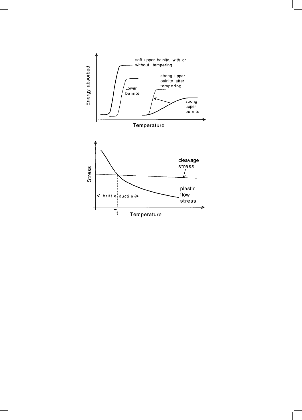
are conducted over a range of temperatures, and a plot of the impact toughness
versus temperature is called an impact transition curve, which has a sigmoidal
shape (Fig. 12.7a). The ¯at region of the curve at high temperatures is the upper
shelf which represents ductile failure. The corresponding ¯at region at lower
temperatures is called the lower shelf and represents cleavage failure. In
between these is the transition region with mixed cleavage and ductile fracture.
The impact transition temperature (T
t
) is usually de®ned that at which the
fracture surface shows 50% cleavage fracture.
The Charpy test is empirical in that the data cannot be used directly in
engineering design. It does not provide the most searching mechanical condi-
tions. The sample has a notch, but this is less than the atomically sharp brittle
crack. Although the test involves impact loading, there is a requirement to start
a brittle crack from rest at the tip of the notch, suggesting that the test is
optimistic in its comparison against a propagating brittle crack (Cottrell,
Bainite in Steels
[13:38 3/9/01 C:/3B2 Templates/keith/3750 BAINITE.605/3750-012.3d] Ref: 0000 Auth: Title: Chapter 00 Page: 298 285-342
298
1995). Most materials can be assumed to contain sub-critical cracks so that the
initiation of a crack seems seldom to be an issue.
The Charpy test is nevertheless a vital quality control measure which is
speci®ed widely in international standards, and in the ranking of samples in
research and development exercises. It is the most common ®rst assessment of
toughness and in this sense has a proven record of reliability. The test is
usually carried out at a variety of temperatures in order to characterise the
ductile±brittle transition intrinsic to body-centred cubic metals with their large
Peierls barriers to dislocation motion. In such metals, the cleavage stress is
insensitive to temperature, the stress required for plastic ¯ow rises rapidly
as the temperature decreases (Fig. 12.7b). The increase in plastic ¯ow stress
is partly a consequence of the large Peierls barrier but also because of the
Mechanical Properties
[13:38 3/9/01 C:/3B2 Templates/keith/3750 BAINITE.605/3750-012.3d] Ref: 0000 Auth: Title: Chapter 00 Page: 299 285-342
299
Fig. 12.7 Schematic illustration of impact transition curves (a) and of the cause of
the ductile/brittle transition temperature (b) in body-centred cubic metals where
the plastic ¯ow stress is much more sensitive to temperature than the cleavage
stress.

ubiquitous presence of traces of interstitial elements which interact strongly
with dislocation motion.
The curves representing the cleavage and ¯ow stress cross at the transition
temperature, on a plot of stress versus temperature. Below T
t
, cleavage is easier
than plastic ¯ow and vice versa. Any effect which raises the plastic yield stress
(such as constraint caused by a notch) without in¯uencing the nucleation or
growth of cleavage cracks inevitably leads to an increase in T
t
. Cleavage frac-
ture is fast, occurs with little warning, absorbs minimal energy and is undesir-
able; a low transition temperature is therefore an important aim in safe design.
12.5.1 Fully Bainitic Structures
Irvine and Pickering (1963) conducted a major study of the Charpy impact
properties of normalised low-carbon bainitic steels (typical composition Fe±
0.003B±0.5Mn±0.5Mo±0.1C wt%). Their results are important and simple to
interpret because the samples studied were free from proeutectoid ferrite
and almost free of martensite.
y
The impact properties of soft upper bainite were found not to be sensitive to
tempering at temperatures as high as 925 K for 1 hr, as long as the ferrite
retained its plate shape. After all, the upper bainite was obtained by transfor-
mation at high temperatures where tempering occurs during transformation,
so that imposed tempering has only minor further effects on the micro-
structure.
When strong upper bainite is obtained by transformation at lower tempera-
tures, T
t
increases but the upper shelf energy decreases. The ductile±brittle
transition becomes less well-de®ned, the region of the impact curve between
the upper and lower shelves extends over a larger temperature range (Fig.
12.7a). This temperature range becomes narrower, and T
t
and
y
decrease,
on tempering. The larger sensitivity to tempering is consistent with the
lower degree of autotempering expected in bainite generated by transforma-
tion at low temperatures.
Even higher strength can be obtained by transforming to lower bainite,
which surprisingly has good toughness, comparable to the low strength
upper bainite. This is because carbide particles in lower bainite are much
®ner than in upper bainite. Cementite is brittle and cracks under the in¯uence
of the stresses generated by dislocation pile-ups (Hahn et al., 1959). The crack
may then propagate into the ferrite under appropriate conditions of stress and
temperature. The cracks from ®ne cementite particles are smaller and hence
Bainite in Steels
[13:38 3/9/01 C:/3B2 Templates/keith/3750 BAINITE.605/3750-012.3d] Ref: 0000 Auth: Title: Chapter 00 Page: 300 285-342
300
y
It is the combination of low carbon and low substitutional solute concentration, the ease of
cementite precipitation in these steels, and the continuous cooling heat treatment which allow
the bainite reaction to consume all of the austenite.

more dif®cult to propagate into ferrite, which is the reason for the higher
toughness of lower bainite when compared with upper bainite.
Consider a microcrack nucleus as a through thickness Grif®th crack of length
c. The cleavage stress
F
is given (McMahon and Cohen, 1965) by:
F
4E
p
1
2
c
1
2
12:2
where E is the Young's Modulus of ferrite, is its Poisson's ratio and
p
is the
plastic work of fracture per unit area of crack surface, an effective surface
energy. If c is now set equal to the carbide particle thickness c
o
, then the
fracture stress is found to vary as c
o
1
2
. The details of this relationship must of
course vary with the shape of carbide particles but the general relationship
between
F
and c remains the same; for example, when considering mixtures of
ferrite and spheroidal carbides, the stress
F
necessary to propagate cleavage
fracture through the ferrite has been shown to be given by (Curry and Knott,
1978):
F
E
p
1
2
c
d
1
2
12:3
where c
d
is the diameter of the penny-shaped crack resulting from the cleavage
of the spheroidal carbide particle.
The identi®cation of the crack length c with the carbide particle thickness c
o
is a vital assumption which can be justi®ed experimentally for mild steels
containing a microstructure of equiaxed ferrite and cementite particles. This
is a carbide-controlled fracture mechanism, but the alternative possibility is a
grain-size controlled fracture mechanism, in which the fracture stress is that
required to propagate cleavage across grains. The parameter c must then be
identi®ed with a grain size dimension, and in the case of bainite, with a packet
size. Brozzo et al. (1977) have demonstrated that for low-carbon bainitic steels
(containing 0.025±0.50 C wt%) the covariant bainite packet size is the micro-
structural unit controlling cleavage resistance. It is nevertheless possible that
the carbide size controls the cleavage fracture of high-carbon bainitic steels.
12.6 Fracture Mechanics Approach to Toughness
Most bainitic steels are used in high-strength applications and failure is not
usually accompanied by a large amount of plasticity; they are in this sense
`brittle' materials. It is therefore a good approximation to use elasticity theory
to represent the stresses in the vicinity of a sharp crack, even though cleavage
crack propagation in metals always involves a degree of plastic deformation at
the crack tip. Making the further assumption of linear elasticity, we have the
Mechanical Properties
[13:38 3/9/01 C:/3B2 Templates/keith/3750 BAINITE.605/3750-012.3d] Ref: 0000 Auth: Title: Chapter 00 Page: 301 285-342
301

linear-elastic-fracture-mechanics (LEFM) approximation. One de®nition of a
sharp crack is that the inevitable plastic zone at the crack tip is small enough
to permit the LEFM approximation.
A fracture mechanics approach is more reliable than impact testing because
a toughness value is obtained which is a material property, essentially inde-
pendent of specimen geometry effects. The pre-cracked test samples and con-
ditions such as the strain rate are similar to the conditions experienced during
service. The results can be used quantitatively to predict whether a structure is
likely to fail catastrophically under the in¯uence of the design stress. There are
excellent books and reviews on the subject but a brief introduction is necessary
for an adequate discussion of the work on bainite.
Using LEFM, it is possible to show that when a uniaxial tensile stress is
applied, the stress
r
at a distance r ahead of a sharp crack tip is given by
r
K
I
2r
1
2
12:4
where K
I
is a stress intensi®cation factor in mode I (tensile) loading. K
I
is a
function of the applied stress and of the specimen geometry:
K
I
Yfc=Wg12:5
where Y is a compliance function which depends on the crack length c and on
the specimen width W. For a body of in®nite extent, containing a central
through-thickness crack of length 2c, normal to , Y c
1
2
. For brittle materi-
als, K
I
at fracture takes a unique critical value K
IC
. The latter is then indepen-
dent of W or other dimensional variables; it is a material constant which can be
used to design against catastrophic failure in service.
12.6.1 Microstructural Interpretation of K
IC
In considering the role of microstructure in fracture, it is necessary to distin-
guish between `large' and `small' particles. With small particles, the phenom-
enon controlling fracture is the propagation of particle-sized microcracks into
the surrounding ferrite matrix. For larger particles the cracking of the particle
represents the critical event, after which the crack propagates into the matrix
and across grain boundaries (Gibson, 1988; Burdekin, 1990). For the most part,
high-strength steels such as bainitic or martensitic alloys should, if
manufactured properly, lie in the small particle regime, where we shall
focus attention.
It is sometimes possible to relate K
IC
values to microstructural and micro-
mechanistic parameters. It can be argued that the critical value of stress inten-
sity which leads to failure must be associated with corresponding critical
values of stress
C
and distance r
C
(Knott and Cottrell, 1963; Knott, 1966;
Ritchie et al., 1973; Knott, 1981):
Bainite in Steels
[13:38 3/9/01 C:/3B2 Templates/keith/3750 BAINITE.605/3750-012.3d] Ref: 0000 Auth: Title: Chapter 00 Page: 302 285-342
302

K
IC
C
2r
c
1
2
12:6
where
C
is usually identi®ed with
F
(eq. 12.2), the local stress required to
propagate a microcrack nucleus.
F
varies with carbide thickness, or more
generally, with the size of the microcrack nuclei resulting from the fracture
of a brittle phase in the steel; it is relatively independent of temperature.
The interpretation of the distance r
C
is less straightforward. The sample used
in a fracture toughness test contains a machined notch, but to make the speci-
men representative of failure during service, it is fatigue loaded to form a sharp
crack which grows slowly from the root of the notch. Fatigue loading is
stopped as soon as a uniform crack front is established. The specimen is
then ready for toughness testing. The fatigue crack tip is sharp, but not as
sharp as the tip of a cleavage crack. It does not therefore propagate when
the specimen is tensile loaded for the K
IC
test. Instead, the stress ®eld extending
from the fatigue crack tip causes brittle particles within a distance r
C
of the tip
to fracture. The resulting microcrack nuclei are atomically sharp and propagate
into the matrix if the stress
C
is exceeded. The cleavage cracks then link up
with the original fatigue crack and failure occurs rapidly across the specimen
section.
It is emphasised that both r
C
and
C
are for most materials, statistically
averaged quantities, since all microstructural features exhibit variations in
size, shape and distribution. If the carbide particle size and spatial distribution
is bimodal, due perhaps to the presence of a mixture of microstructures, then
the K
IC
values obtained are likely to show much scatter. The stress ®eld extend-
ing from the crack tip effectively samples a ®nite volume and it is the micro-
structure of that volume which determines toughness. Bowen et al. (1986)
found that K
IC
values determined for mixed microstructures of upper and
lower bainite (the former containing coarser cementite) exhibited a large
degree of scatter when compared with a microstructure of just upper bainite
or just martensite.
The microstructural interpretation of K
IC
evidently requires a knowledge of a
local tensile stress and a microstructural distance. This approach has been
successful in explaining the toughness of mild steels with a microstructure
of ferrite and grain boundary cementite (McMahon and Cohen, 1965; Smith,
1966, Knott, 1981) and to a limited extent of steel weld-deposits which have
complex microstructures containing nonmetallic inclusions which initiate fail-
ure (Tweed and Knott, 1983; McRobie and Knott, 1985). In some of these cases,
the critical microstructural features controlling cleavage fracture resistance
have been identi®ed directly, giving faith in the r
C
concept.
Dif®culties arise when attempts are made to use this approach for clean
bainitic or martensitic structures. The carbides particles are so ®ne as to
make a direct identi®cation of r
C
impossible. The fracture stress
F
can never-
Mechanical Properties
[13:38 3/9/01 C:/3B2 Templates/keith/3750 BAINITE.605/3750-012.3d] Ref: 0000 Auth: Title: Chapter 00 Page: 303 285-342
303
theless be measured and if it is shown to be constant, then
F
itself can be used
as a measure of `toughness' (Bowen et al., 1986), although it is not clear how
possible variations in r
C
can be accounted for. A constant
F
indicates that the
critical step in the fracture process is the propagation of a microcrack.
Bowen et al. used this approach, together with K
IC
studies to explain the
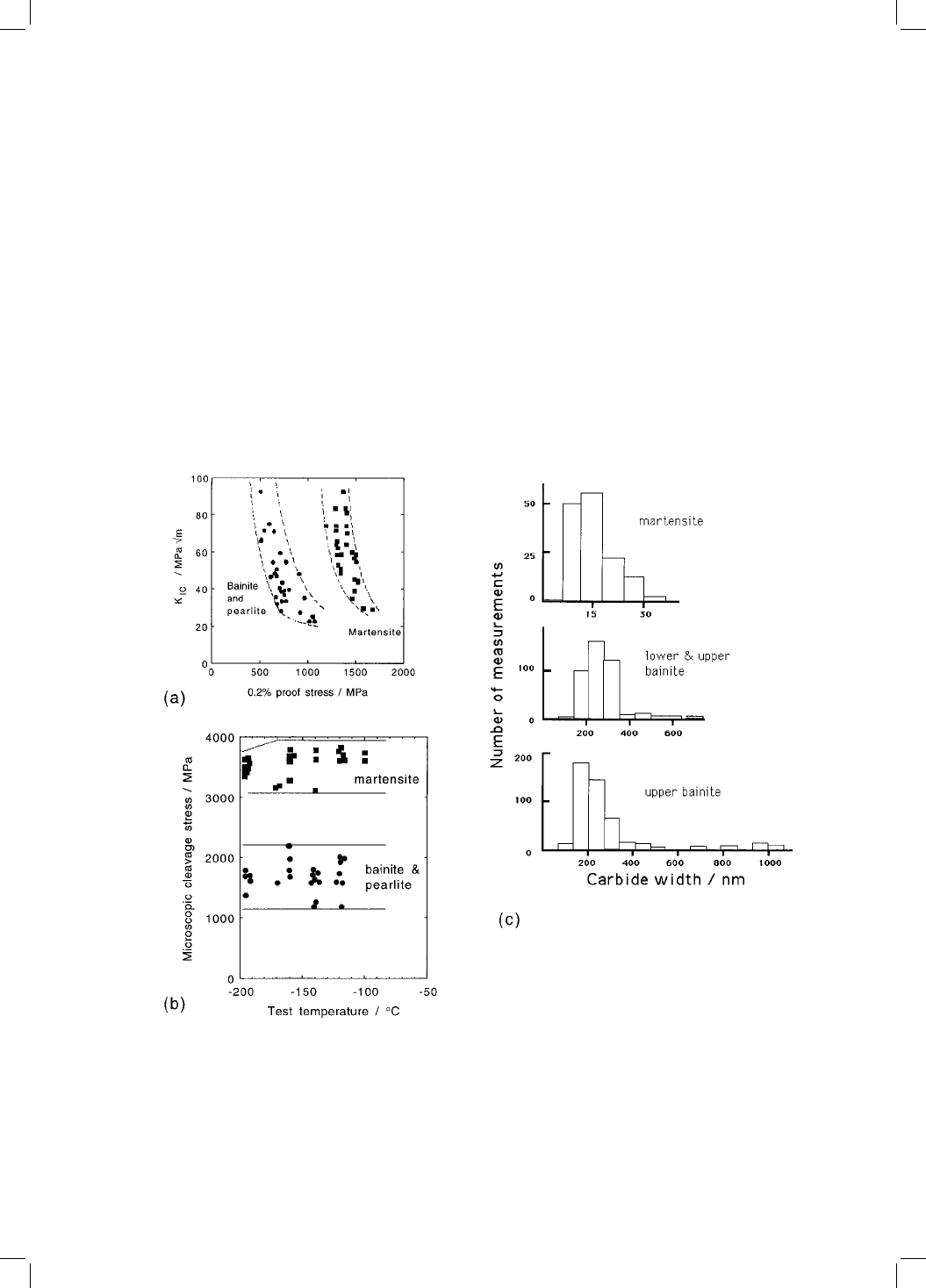
toughness of tempered martensite and bainite in a low-alloy steel. In all
cases, K
IC
values were found to increase with the test temperature over the
range 77±300 K. For the same temperature range, the proof stress decreased
with increasing temperature. For a given proof stress, the toughness of bainite
was always lower than that of tempered martensite (Fig. 12.8). The fracture
stress
F
was in all cases found to be independent of test temperature, but
bainite had a lower
F
than martensite. The results were explained in terms
Bainite in Steels
[13:38 3/9/01 C:/3B2 Templates/keith/3750 BAINITE.605/3750-012.3d] Ref: 0000 Auth: Title: Chapter 00 Page: 304 285-342
304
Fig 12.8 (a) K
IC
values plotted against corresponding values of the 0.2% proof
stress. (b)
F
values plotted against test temperatures. (c) Carbide size distribu-
tions obtained from martensitic and bainitic microstructures (after Bowen et al.).

of measured cementite particle size distributions (Fig. 12.8). They showed that
it is not the mean carbide particle size which determines toughness, but the
coarsest particles to be found in the microstructure. A plot of
F
versus the
reciprocal square root of the coarsest carbide thickness gave a straight line as
predicted by the modi®ed Grif®th equation (eq. 12.2); deviations from this
equation occurred at small particle sizes. On this basis, for a given proof stress,
the toughness is expected (and found) to increase in the order upper bainite,
lower bainite and tempered martensite. Trends like this are also important in
the design of welding processes and materials, and there are many qualitative
results which con®rm that the toughness increases in that order for microstruc-
tures in the heat affected zones of steel welds (Inagaki and Hiroyuki, 1984;
Harrison and Farrar, 1989).
The reason why the modi®ed Grif®th equation fails at small particle sizes is
not clear but it means that
F
becomes relatively insensitive to carbide thick-
ness when the latter is less than about 450 nm.
It must not be assumed that these results spell doom for bainitic microstruc-
tures; they need not always have poor toughness relative to tempered marten-
site. The size of bainitic carbides can be controlled using suitable alloying
additions. Indeed, the carbides can be eliminated completely by adding suf®-
cient Si or Al to the steel. The results are valid only for clean steels in which the
fracture mechanism is carbide-nucleated and growth-controlled. That the coar-
seness of carbides controls the toughness of bainite in clean steels is empha-
sised by the observation that lower bainite with its ®ner carbides and higher
strength nevertheless has a better toughness than the softer upper bainite. All
other things being equal, toughness is expected to improve as the strength is
reduced, making plastic deformation easy.
The micromechanistic model for the toughness of bainite contains the terms
C
and r
C
, the former de®ning the stress to propagate a microcrack in a cemen-
tite particle, and the latter the distance over which the stress is large enough to
cause carbide cracking. The distance r
C
is expected to be small in comparison
with the width of a bainite sheaf, so the toughness of bainite or martensite
should not be dependent on the austenite grain size or the bainite packet size.
This prediction has been demonstrated to be the case for tempered martensite
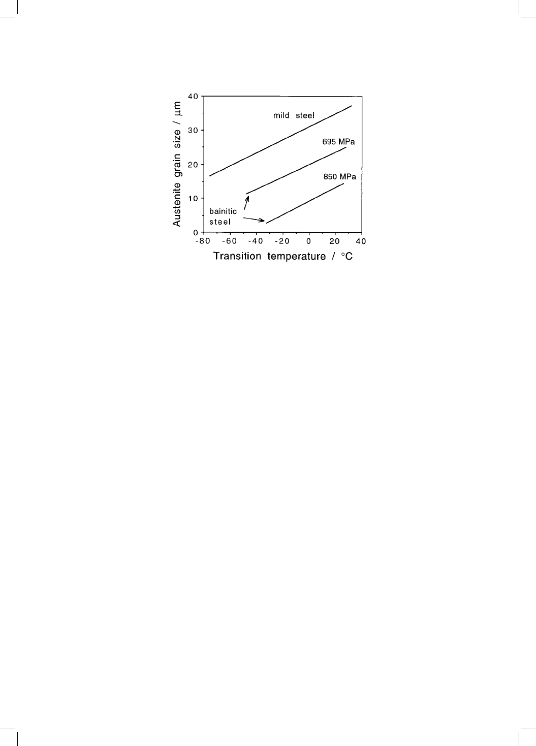
(Bowen et al.) but contradictory results exist for bainite. Naylor and Krahe
(1974) using notched-bar impact tests have shown that a re®nement in the
bainite packet size leads to an improvement in toughness. The impact transi-
tion temperature of bainitic steels is also found to decrease as the austenite
grain size decreases (Fig. 12.9), although this might be because the packet size
becomes ®ner at small austenite grain sizes. The austenite grain size in Irvine
and Pickering's experiments was varied by controlling the temperature at
which hot-rolling ®nished, or by reheating into the austenite phase ®eld, before
the steel was continuously cooled to bainite.
Mechanical Properties
[13:38 3/9/01 C:/3B2 Templates/keith/3750 BAINITE.605/3750-012.3d] Ref: 0000 Auth: Title: Chapter 00 Page: 305 285-342
305
The fracture stress
F
and the critical distance r
C
do not vary much with
temperature, although K
IC
for bainite is found experimentally to increase as the
test temperature rises. This apparent contradiction arises because of the LEFM
approximation. In practice, the effect of temperature is to reduce the yield
strength. The size of the plastic zone at the crack tip increases so that more
work is done as the crack propagates, leading to an increase in K
IC
(Ritchie et
al., 1973).
Finally, it is worth noting that the austenite grain size cannot always be
varied independently. Some carbides may not dissolve if the required grain
size is achieved using a low austenitising temperature; these carbides can be
detrimental to toughness (Tom, 1973). As the solubility of the carbides
increases with austenitising temperature, so does the average carbon concen-
tration in the austenite; more of the austenite is therefore retained to ambient
temperature after partial transformation to martensite or bainite (Mendiratta et
al., 1972; Kar et al., 1979). Variations in austenite grain size also in¯uence
hardenability; a ®ne grain structure can be detrimental if it causes the forma-
tion of transformation products such as allotriomorphic ferrite during cooling
of a high strength steel (Parker and Zackay, 1975).
12.6.2 Cleavage Fracture Path
Microstructural observations have demonstrated that during cleavage failure,
the cracks propagate undeviated across individual packets of bainite
(Pickering, 1967).
y
Similar results have been reported for weld deposits,
Bainite in Steels
[13:38 3/9/01 C:/3B2 Templates/keith/3750 BAINITE.605/3750-012.3d] Ref: 0000 Auth: Title: Chapter 00 Page: 306 285-342
306
Fig. 12.9 Variation in the impact transition temperature as a function of the aus-
tenite grain size (after Irvine and Pickering, 1963).