Bichop R.H. (Ed.) Mechatronic Systems, Sensors, and Actuators: Fundamentals and Modeling
Подождите немного. Документ загружается.

20-94 Mechatronic Systems, Sensors, and Actuators
Worst-case range measurement accuracy is ±5 cm, with typical values of around ±2 cm. The pulsed near-
infrared laser is Class-1 eye-safe under all operating conditions.
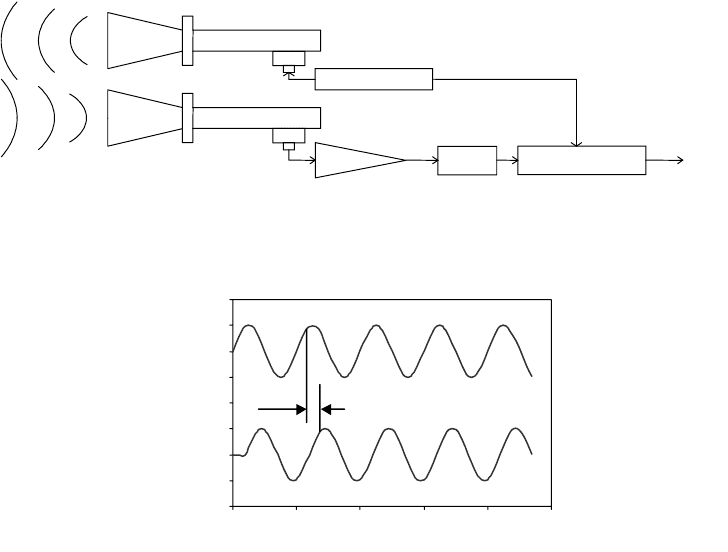
Microwave Range Sensors
Microwave technology may be used to measure motion, velocity, range, and direction of motion
(Figure 20.68). The sensors are rugged since they have no moving parts. They can be operated safely in
explosive environments, because the level of energy used is very low (no risk for sparks). Their operating
temperatures range from −55°C to +125°C. They can work in environments with dust, smoke, poisonous
gases, and radioactivity (assuming the components are hardened for radiation). Typically microwave
sensors are used to measure ranges from 25 to 45,000 mm, but longer ranges are possible depending on
power and object size. The reflected power returning to the receiver decreases as the fourth power of the
distance to the object. Typical wavelength used ranges from 1 to 1000 mm.
Time-of-flight is in the order 2 ns per foot of range (reach the target and return). This translates into
10.56 ms per mile of range. Measuring short ranges may pose a problem. For 1 in. resolution, the circuit
must resolve 167 ps. An alternate method more suitable to measure short distances is based on a frequency
sweep of the signal generator. In this case, the return signal remains at the initial frequency (usually
10.525 GHz), and it is compared with the current frequency changed by a sweep rate. For example, to
measure a range of 3 ft, one may sweep at 5 MHz/ms. After 6 ns, the frequency changes by 30 Hz (6 ns ×
5 MHz/0.001 s). In this case, 0.0256 mm (0.001 in.) may be resolved easily. When using this method, a
signal amplifier that increases gain with frequency is necessary. See section “Frequency Modulation” for
more details on frequency modulation methods.
Phase Measurement
Time-of-flight (TOF) is defined as a phase shift between emitted and received signals when the dis-
tance is less than one wavelength (Figure 20.69). Given a phase shift f, the distance is calculated as
FIGURE 20.68 The microwave sensor, unlike the motion detector, requires a separate transmitter and receiver.
(Adapted from Williams, 1989.)
FIGURE 20.69 Range from phase measurement.
Ph
a
se
Locked
L
oo
p
Output
Receiver
Transmitter
Filter
Preamp
Modulator
Phase locked
loop
1
2
2345
Emitted signal
Return signal
Phase
1
2
3
4
5
6
7
8
0
0
Amplitude
Time
9258_C020_Sect_7-9.fm Page 94 Tuesday, October 9, 2007 9:09 PM

Sensors 20-95
if the emitter and receiver are at the same location, or if
the receiver is attached to the target, where c is the speed of travel,
φ
is the measured phase, and f is the
modulation frequency.
The phase shift between outgoing and reflected sine waves can be measured by multiplying the two
signals together in an electronic mixer, then averaging the product over many modulation cycles
(Woodbury et al., 1993). This integrating process can be relatively time consuming, making it difficult to
achieve extremely rapid update rates. The result can be expressed mathematically as follows (Woodbury
et al., 1993):
(20.70)
which reduces to
(20.71)
where t is the time, T is the averaging interval, and A is the amplitude factor from gain of integrating
amplifier.
From the earlier expression for
φ
, it can be seen that the quantity actually measured is in fact the cosine
of the phase shift and not the phase shift itself (Woodbury et al., 1993). This situation introduces a so-
called ambiguity interval for scenarios where the round-trip distance exceeds the modulation wavelength
λ
(i.e., the phase measurement becomes ambiguous once
φ
exceeds 360°). Conrad and Sampson (1990)
define this ambiguity interval as the maximum range that allows the phase difference to go through one
complete cycle of 360°:
(20.72)
where R
a
is the ambiguity range interval.
Referring to Equation 20.73, it can be seen that the total round-trip distance 2d is equal to some integer
number of wavelengths n
λ
plus the fractional wavelength distance x associated with the phase shift. Since
the cosine relationship is not single-valued for all of
φ
, there will be more than one distance d corre-
sponding to any given phase-shift measurement (Woodbury et al., 1993):
(20.73)
where
d = (x + n
λ
)/2 = true distance to target,
x = distance corresponding to differential phase
φ
,
n = number of complete modulation cycles.
Careful re-examination of Equation 20.73, in fact, shows that the cosine function is not single-valued
even within a solitary wavelength interval of 360
°
. Accordingly, if only the cosine of the phase angle is
measured, the ambiguity interval must be further reduced to half the modulation wavelength, or 180
°
(Scott,
1990). In addition, the slope of the curve is such that the rate of change of the nonlinear cosine function is
not constant over the range of 0
≤
φ
≤
180
°
, and is in fact zero at either extreme. The achievable accuracy
of the phase-shift measurement technique thus varies as a function of target distance, from best-case
d
φλ
/4
πφ
c/4
π
f== d
φλ
/2
πφ
c/2
π
f==
1
T
---
T→∞
lim
2
π
c
λ
---------
t
4
π
d
λ
----------
+
2
π
c
λ
---------
sinsin dt
0
T
A
4
π
d
λ
----------
cos
R
a
c
2f
----
=
φ
4
π
d
λ
---------
cos
2
π
xn
λ
+()
λ
---------------------------
cos==cos
9258_C020_Sect_7-9.fm Page 95 Tuesday, October 9, 2007 9:09 PM
20-96 Mechatronic Systems, Sensors, and Actuators
performance for a phase angle of 90
°
to worst case at 0 and 180
°
. For this reason, the useable measurement
range is typically even further limited to 90% of the 180
°
ambiguity interval (Chen et al., 1993).
A common solution to this problem involves taking a second measurement of the same scene but with
a 90° phase shift introduced into the reference waveform, the net effect being the sine of the phase angle
is then measured instead of the cosine. This additional information (i.e., both sine and cosine measure-
ments) can be used to expand the phase angle ambiguity interval to the full 360° limit previously discussed
(Scott, 1990). Furthermore, an overall improvement in system accuracy is achieved, as for every region
where the cosine measurement is insensitive (i.e., zero slope), the complementary sine measurement will
be at peak sensitivity (Woodbury et al., 1993).
Nevertheless, the unavoidable potential for erroneous information as a result of the ambiguity interval
is a detracting factor in the case of phase-detection schemes. Some applications simply avoid such
problems by arranging the optical path in such a fashion as to ensure the maximum possible range is
always less than the ambiguity interval (Figure 20.70). Alternatively, successive measurements of the same
target using two different modulation frequencies can be performed, resulting in two equations with two
unknowns, allowing both x and n (in the previous equation) to be uniquely determined. Kerr (1988)
describes such an implementation using modulation frequencies of 6 and 32 MHz.
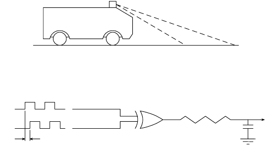
For square-wave modulation at the relatively low frequencies typical of ultrasonic systems (20–
200 kHz), the phase difference between incoming and outgoing waveforms can be measured with the
simple linear circuit shown in Figure 20.71 (Figueroa & Barbieri, 1991a). The output of the exclusive-or
gate goes high whenever its inputs are at opposite logic levels, generating a voltage across capacitor C
1
that is proportional to the phase shift. For example, when the two signals are in phase (i.e.,
φ
= 0), the
gate output stays low and V is zero; maximum output voltage occurs when
φ
reaches 180°. While easy
to implement, this simplistic approach is limited to very low frequencies and may require frequent
calibration to compensate for drifts and offsets due to component aging or changes in ambient conditions
(Figueroa & Lamancusa, 1992).
Extended Range Phase Measurement Systems
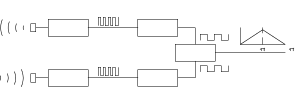
Figueroa and Barbieri (1991a; 1991b) report an interesting method for extending the ambiguity interval
in ultrasonic phase-detection systems through frequency division of the received and reference signals.
Since the span of meaningful comparison is limited (best case) to one wavelength,
λ
, it stands to reason
that decreasing the frequency of the phase detector inputs by some common factor will increase
λ
by a
similar amount. The concept is illustrated in Figure 20.72. Due to the very short wavelength of ultrasonic
energy (i.e., about 0.25 in. for the Polaroid system at 49.1 kHz), the total effective range is still only 4 in.
FIGURE 20.70 By limiting the maximum distance measured to be less than the range ambiguity interval R
a
,
erroneous distance measurements can be avoided.
FIGURE 20.7 At low frequencies typical of ultrasonic systems, a simple phase-detection circuit based on an exclusive-
or gate will generate an analog output voltage proportional to the phase difference seen by the inputs. (Adapted from
Figueroa & Barbieri, 1991a.)
MDARS
security
Maximum range
V
Reference
Phase difference
Signal
XOR Gate
R
C
1
9258_C020_Sect_7-9.fm Page 96 Tuesday, October 9, 2007 9:09 PM
Sensors 20-97
after dividing the detector inputs by a factor of 16. Due to this inherent range limitation, ultrasonic phase-
detection ranging systems are not extensively applied in mobile robotic applications, although Figueroa
and Lamancusa (1992) describe a hybrid approach used to improve the accuracy of TOF ranging for
three-dimensional position location.
An ingenious method to measure range using phase information was developed by Young and Li (1992).
The method reconstructs the total range by piecing together multiple consecutive phase chunks that reset
every 2
π
radians of phase difference between emitted and received signals. This is another method that
overcomes the limitation of phase-based systems to ranges shorter than one acoustic wavelength. The
discontinuities at every 2
π
radians are eliminated by first taking the derivative of the phase, resulting in a
smooth signal with sharp pulses (impulses) at the location of each discontinuity. Subsequently, the pulses
are ignored and the result is integrated and multiplied by a constant to reconstruct the overall range. The
method was tested with an experiment that employed 40 kHz transducers. Distances from 40 to 400 mm
were measured with errors from ±0.1629 to ±0.4283 mm.
Laser-based continuous-wave ranging originated out of work performed at the Stanford Research
Institute in the 1970s (Nitzan et al., 1977). Range accuracies approach those achievable by pulsed laser
TOF methods. Only a slight advantage is gained over pulsed TOF rangefinding, however, since the difficult
time-measurement problem is replaced by the need for fairly sophisticated phase-measurement electron-
ics (Depkovich & Wolfe, 1984). In addition, problems with the phase-shift measurement approach are
routinely encountered in situations where the outgoing energy is simultaneously reflected from two target
surfaces at different distances from the sensor, as for example when scanning past a prominent vertical
edge (Hebert & Krotkov, 1991).
The system electronics are set up to compare the phase of a single incoming wave with that of the
reference signal and are not able to cope with two superimposed reflected waveforms. Adams (1993)
describes a technique for recognizing the occurrence of this situation in order to discount the resulting
erroneous data.
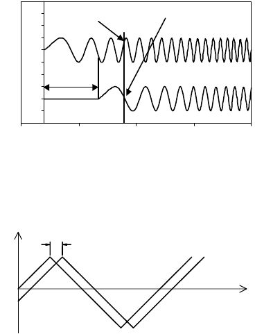
Frequency Modulation
This is a method devised to improve the accuracy in detecting the time-of-arrival of the wave to the
receiver. Instead of a single frequency wave, a frequency modulated wave of the form f = f
0
+ kt is emitted.
The difference between the emitted and received frequency at any time is ∆f = kt − k(t − t
f
) = kt
f
(Figure 20.73). The advantage of this method is that one does not need to know exactly when the wave
arrived to the receiver. However, accurate real-time frequency measurement electronics must be used,
and the transducers must respond within the frequency band sweep. Modulation other than linear is
also possible in order to improve signal-to-noise ratio and hence accuracy.
The signal is reflected from a target and arrives at the receiver at time t + T:
where T is the round-trip propagation time, d is the distance to target, and c is the speed of travel.
FIGURE 20.72 Dividing the input frequencies to the phase comparator by some common integer value will extend
the ambiguity interval by the same factor, at the expense of resolution. (Adapted from Figueroa & Barbieri, 1991a.)
Transmiitted
TTL sinc
Received
TTL wave
Phase
2
Receiver
to TTL
Transmitter
Function
generator
Frequency
divider
Frequency
divider
Phase
detection
Volts
T
2d
c
------
=
9258_C020_Sect_7-9.fm Page 97 Tuesday, October 9, 2007 9:09 PM
20-98 Mechatronic Systems, Sensors, and Actuators
The received signal is compared with a reference signal taken directly from the transmitter. The received
frequency curve (Figure 20.74) will be displaced along the time axis relative to the reference frequency
curve by an amount equal to the time required for wave propagation to the target and back. (There might
also be a vertical displacement of the received waveform along the frequency axis, due to the Doppler
effect.) These two frequencies when combined in the mixer produce a beat frequency F
b
:
where k is a constant.
This beat frequency is measured and used to calculate the distance to the object:
where
d = range to target,
c = speed of light,
F
b
= beat frequency,
F
r
= repetition (modulation) frequency,
F
d
= total FM frequency deviation.
Distance measurement is therefore directly proportional to the difference or beat frequency and is as
accurate as the linearity of the frequency variation over the counting interval.
Advances in wavelength control of laser diodes now permit this ultrasonic and radar ranging technique
to be used with lasers. The frequency or wavelength of a laser diode can be shifted by varying its
temperature. Consider an example where the wavelength of an 850-nm laser diode is shifted by 0.05 nm
in 4
µ
s: the corresponding frequency shift is 5.17 MHz/ns. This laser beam, when reflected from a surface
FIGURE 20.73 The frequency difference between the emitted signal and received signal is proportional to the time-
of-flight at any given time.
FIGURE 20.74 The received frequency curve is shifted along the time axis relative to the reference frequency.
0
1
2
3
4
5
6
7
8
9
10
–2 3 8 13 18
Time
Amplitude
Emitted signal
Return signal
Time-of-flight
t
f
Frequency f = f
0
+ kt
Frequency f = f
0
+ k (t -t
f
)
t
f
f
o
t
2d/c
F
b
ft()= fT t+()– kT=
d
F
b
c
4F
r
F
d
-------------
=
9258_C020_Sect_7-9.fm Page 98 Tuesday, October 9, 2007 9:09 PM
Sensors 20-99
1 m away, would produce a beat frequency of 34.5 MHz. The linearity of the frequency shift controls the
accuracy of the system.
The frequency-modulation approach has an advantage over the phase-shift measurement technique
in which a single distance measurement is not ambiguous. (Recall that phase-shift systems must perform
two or more measurements at different modulation frequencies to be unambiguous.) However, frequency
modulation has several disadvantages associated with the required linearity and repeatability of the
frequency ramp, as well as the coherence of the laser beam in optical systems. As a consequence, most
commercially available FMCW ranging systems are radar based, while laser devices tend to favor TOF
and phase-detection methods.
Triangulation Ranging
Triangulation ranging is based upon an important premise of plane trigonometry, which states that given
the length of a side and two angles of a triangle, it is possible to determine the length of the other sides
and the remaining angle. The basic Law of Sines can be rearranged as shown below to represent the length
of side B as a function of side A and the angles
θ
and
φ
:
In ranging applications, length B would be the desired distance to the object of interest at point P
3
(Figure 20.75) for known sensor separation baseline A.
Triangulation ranging systems are classified as either passive (use only the ambient light of the scene)
or active (use an energy source to illuminate the target). Passive stereoscopic ranging systems position
directional detectors (video cameras, solid-state imaging arrays, or position sensitive detectors) at posi-
tions corresponding to locations P
1
and P
2
(Figure 20.76). Both imaging sensors are arranged to view
the same object point, P
3
, forming an imaginary triangle. The measurement of angles
θ
and
φ
in
conjunction with the known orientation and lateral separation of the cameras allows the calculation of
range to the object of interest.
Active triangulation systems, on the other hand, position a controlled light source (such as a laser) at
either point P
1
or P
2
, directed at the observed point P
3
. A directional imaging sensor is placed at the
remaining triangle vertex and is also aimed at P
3
. Illumination from the source will be reflected by the
FIGURE 20.75 Triangulation ranging systems determine range B to target point P
3
by measuring angles f and q at
points P
1
and P
2
.
FIGURE 20.76 Passive stereoscopic ranging system configuration.
P
3
P
2
A
ø
θ
α
P
1
B
Camera 2
A
Camera 1
P
1
P
3
P
2
ø
θ
9258_C020_Sect_7-9.fm Page 99 Tuesday, October 9, 2007 9:09 PM
20-100 Mechatronic Systems, Sensors, and Actuators
target, with a portion of the returned energy falling on the detector. The lateral position of the spot as
seen by the detector provides a quantitative measure of the unknown angle
φ
, permitting range deter-
mination by the Law of Sines.
The performance characteristics of triangulation systems are to some extent dependent on whether
the system is active or passive. Passive triangulation systems using conventional video cameras require
special ambient lighting conditions that must be artificially provided if the environment is too dark.
Furthermore, these systems suffer from a correspondence problem resulting from the difficulty in match-
ing points viewed by one image sensor with those viewed by the other. On the other hand, active
triangulation techniques employing only a single detector do not require special ambient lighting, nor
do they suffer from the correspondence problem. Active systems, however, can encounter instances of
no recorded strike because of specular reflectance or surface absorption of the light.
Limiting factors common to all triangulation sensors include reduced accuracy with increasing range,
angular measurement errors, and a missing parts (also known as shadowing) problem. Missing parts refers
to the scenario where particular portions of a scene can be observed by only one viewing location (P
1
or
P
2
). This situation arises because of the offset distance between P
1
and P
2
, causing partial occlusion of the
target (i.e., a point of interest is seen in one view but otherwise occluded or not present in the other). The
design of triangulation systems must include a tradeoff analysis of the offset: as this baseline measurement
increases, the range accuracy increases, but problems due to directional occlusion worsen.
Stereo Disparity
The first of the triangulation schemes to be discussed, stereo disparity (also called stereo vision, binocular
vision, and stereopsis) is a passive ranging technique modeled after the biological counterpart. When a
three-dimensional object is viewed from two locations on a plane normal to the direction of vision, the
image as observed from one position is shifted laterally when viewed from the other. This displacement
of the image, known as disparity, is inversely proportional to the distance to the object. Humans sub-
consciously verge their eyes to bring objects of interest into rough registration (Burt et al., 1992). Hold
up a finger a few inches away from your face while focusing on a distant object and you can simultaneously
observe two displaced images in the near field. In refocusing on the finger, your eyes actually turn inward
slightly to where their respective optical axes converge at the finger instead of infinity.
Most implementations use a pair of identical video cameras (or a single camera with the ability to
move laterally) to generate the two disparity images required for stereoscopic ranging. The cameras are
typically aimed straight ahead viewing approximately the same scene, but (in simplistic cases anyway)
do not possess the capability to verge their center of vision on an observed point, as can human eyes.
This limitation makes placement of the cameras somewhat critical because stereo ranging can take place
only in the region where the fields of view overlap. In practice, analysis is performed over a selected range
of disparities along the Z axis on either side of a perpendicular plane of zero disparity called the horopter
(Figure 20.77). The selected image region in conjunction with this disparity range defines a three-dimen-
sional volume known as the stereo observation window (Burt et al., 1993).
More recently there has evolved a strong interest within the research community for dynamically
reconfigurable camera orientation (Figure 20.78), often termed active vision in the literature (Aloimonos
et al., 1987; Swain & Stricker, 1991; Wavering et al., 1993). The widespread acceptance of this terminology
is perhaps somewhat unfortunate in view of potential confusion with stereoscopic systems employing
an active illumination source (see section 4.1.3). Verging ste reo, another term in use, is perhaps a more
appropriate choice. Mechanical verging is defined as the process of rotating one or both cameras about
the vertical axis in order to achieve zero disparity at some selected point in the scene (Burt et al., 1992).
There are four basic steps involved in the stereo ranging process (Poggio, 1984):
•
A point in the image of one camera must be identified (Figure 20.79, left).
•
The same point must be located in the image of the other camera (Figure 20.79, right).
•
The lateral positions of both points must be measured with respect to a common reference.
•
Range Z is then calculated from the disparity in the lateral measurements.
9258_C020_Sect_7-9.fm Page 100 Tuesday, October 9, 2007 9:09 PM
Sensors 20-101
On the surface this procedure appears rather straightforward, but difficulties arise in practice when
attempting to locate the specified point in the second image (Figure 20.79). The usual approach is to
match “interest points” characterized by large intensity discontinuities (Conrad & Sampson, 1990). Match-
ing is complicated in regions where the intensity and/or color are uniform (Jarvis, 1983b). Additional
factors include the presence of shadows in only one image (due to occlusion) and the variation in image
characteristics that can arise from viewing environmental lighting effects from different angles. The
effort to match the two images of the point is called
correspondence
, and methods for minimizing this
FIGURE 20.77 The stereo observation window is that volume of interest on either side of the plane of zero disparity
known as the horopter. (Courtesy David Sarnoff Research Center.)
FIGURE 20.78 This stereoscopic camera mount uses a pair of lead-screw actuators to provide reconfigurable
baseline separation and vergence as required. (Courtesy Robotic Systems Technology, Inc.)
Z
k
j
z
Resolution
cell
Stereo
observation
window
Camera
field of
view
Θ
Horopter
δ
θ
9258_C020_Sect_7-9.fm Page 101 Tuesday, October 9, 2007 9:09 PM
20-102 Mechatronic Systems, Sensors, and Actuators
computationally expensive procedure are widely discussed in the literature (Nitzan, 1981; Jarvis, 1983a;
Poggio, 1984; Loewenstein, 1984; Vuylsteke et al., 1990; Wildes, 1991).
Probably the most basic simplification employed in addressing the otherwise overwhelming correspon-
dence problem is seen in the epipolar restriction that reduces the two-dimensional search domain to a
single dimension (Vuylsteke et al., 1990). The epipolar surface is a plane defined by the point of interest
P and the positions of the left and right camera lenses at L and R, as shown in Figure 20.80. The
intersection of this plane with the left image plane defines the left epipolar line as shown. As can be seen
from the diagram, since the point of interest P lies in the epipolar plane, its imaged point P
l
must lie
somewhere along the left epipolar line. The same logic dictates that the imaged point P
r
must lie along a
similar right epipolar line within the right image plane. By carefully aligning the camera image planes
such that the epipolar lines coincide with identical scan lines in their respective video images, the
correspondence search in the second image is constrained to the same horizontal scan line containing
the point of interest in the first image. This effect can also be achieved with nonaligned cameras by careful
calibration and rectification (resampling).
To reduce the image processing burden, most correspondence schemes monitor the overall scene at
relatively low resolution and examine only selected areas in greater detail. A foveal representation analo-
gous to the acuity distribution in human vision is generally employed as illustrated in Figure 20.81,
allowing an extended field-of-view without loss of resolution or increased computational costs (Burt
et al., 1993). The high-resolution fovea must be shifted from frame to frame in order to examine different
regions of interest individually. Depth acuity is greatest for small disparities near the horopter and falls
off rapidly with increasing disparities (Burt et al., 1992).
Active Triangulation
Rangefinding by active triangulation is a variation on the stereo disparity method of distance measure-
ment. In place of one camera is a laser (or LED) light source aimed at the surface of the object of interest.
FIGURE 20.79 Range Z is derived from the measured disparity between interest points in the left and right camera
images. (Courtesy David Sarnoff Research Center.)
FIGURE 20.80 The epipolar surface is a plane defined by the lens centerpoints L and R and the object of interest
at P. (Adapted from Vuylsteke et al., 1990.)
δθ
Φ
Θ
local
pattern
i
Range (Z )
Camera
field of
view
k
j
L
R
Step ( z)
Analysis
window
δ
P
l
P
r
P
R
L
R
1
9258_C020_Sect_7-9.fm Page 102 Tuesday, October 9, 2007 9:09 PM
Sensors 20-103
The remaining camera is offset from this source by a known distance A and configured to hold the
illuminated spot within its field of view (Figure 20.82).
For one- or two-dimensional array detectors such as vidicon or CCD cameras, the range can be
determined from the known baseline distance A and the relative position of the laser-spot image on the
image plane. For mechanically scanned single-element detectors such as photodiodes or phototransistors,
the rotational angles of the detector and/or source are measured at the exact instant the detector observes
the illuminated spot. The trigonometric relationships between these angles and the baseline separation
are used (in theory) to compute the distance. To obtain three-dimensional information for a volumetric
region of interest, laser triangulators can be scanned in both azimuth and elevation. In systems where
the source and detector are self-contained components, the entire configuration can be moved mechan-
ically. In systems with movable optics, the mirrors and lenses are generally scanned in synchronization
while the laser and detector remain stationary.
Drawbacks to active triangulation include the missing parts situation, where points illuminated by the
light source cannot be seen by the camera and vice versa (Jarvis, 1983b), as well as surface absorption
or specular reflection of the irradiating energy (see Chapter 9). On the positive side, however, point-
source illumination of the image effectively eliminates the correspondence problem encountered in stereo
disparity rangefinders. There is also no dependence on scene contrast, and reduced influence from
ambient lighting effects. (Background lighting is effectively a noise source that can limit range resolution.)
FIGURE 20.81 The foveal stereo representation provides high acuity near the center of the observation window,
with decreasing resolution towards the periphery. (Courtesy David Sarnoff Research Center.)
FIGURE 20.82 An active triangulation-ranging configuration employing a conventional CCD array as the detector.
Foveal
observation
window
Footprint
Laser
Camera
A
θ
Target object
φ
9258_C020_Sect_7-9.fm Page 103 Tuesday, October 9, 2007 9:09 PM