Bryant A.C. Refrigeration equipment
Подождите немного. Документ загружается.

120
RefrigerationEquipment
only when the compressor is operating, preventing oil and refrigerant from
draining to the compressor crankcase during off cycles.
To minimize refrigerant condensation in the oil separator it should be
installed as close to the compressor as possible, preferably in a warm location.
The separator may be insulated to retard heat loss when the compressor stops.
An indicating sight glass and a hand shut-off valve are installed in the oil
return line. In conjunction with the sight glass the shut-off valve can be used
as a throttling device; it is adjusted so that liquid flow (oil and refrigerant)
from the separator can be controlled to the compressor crankcase.
Discharge line mufflers
In the event of noise or vibration from gas pulsations, discharge mufflers are
recommended and must be installed for the free draining of oil.
As previously stated, when compressors are idle the oil adhering to the
inner surfaces of the discharge line risers will drain to the bottom of the
risers. With a 3 m riser, plus the discharge muffler, the amount of oil can be
quite considerable.
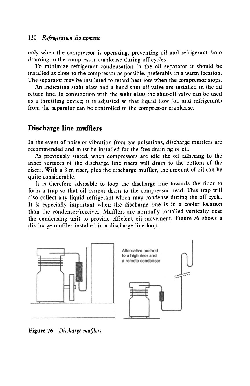
It is therefore advisable to loop the discharge line towards the floor to
form a trap so that oil cannot drain to the compressor head. This trap will
also collect any liquid refrigerant which may condense during the off cycle.
It is especially important when the discharge line is in a cooler location
than the condenser/receiver. Mufflers are normally installed vertically near
the condensing unit to provide efficient oil movement. Figure 76 shows a
discharge muffler installed in a discharge line loop.
Figure 76
Discharge mufflers
Pipework and oil traps 121
Parallel pipework
When compressors are installed in parallel and share common suction and
discharge lines, they are usually open-type units. Hermetic and semi-hermetic
units are not used in case of a motor failure. The high temperatures resulting
from the motor failure of one motor compressor can cause a chemical break-
down of the refrigerant and oil, resulting in the contamination of the whole
system.
However, two or more hermetic or semi-hermetic units can be used to
accommodate a common load. When this is required each compressor is
connected to an independent circuit within the evaporator and the condenser,
so that they function without the possibility of cross-contamination. A single
condenser is normally preferred for ease of control, but a separate condenser
may be used for each compressor.
Discharge lines
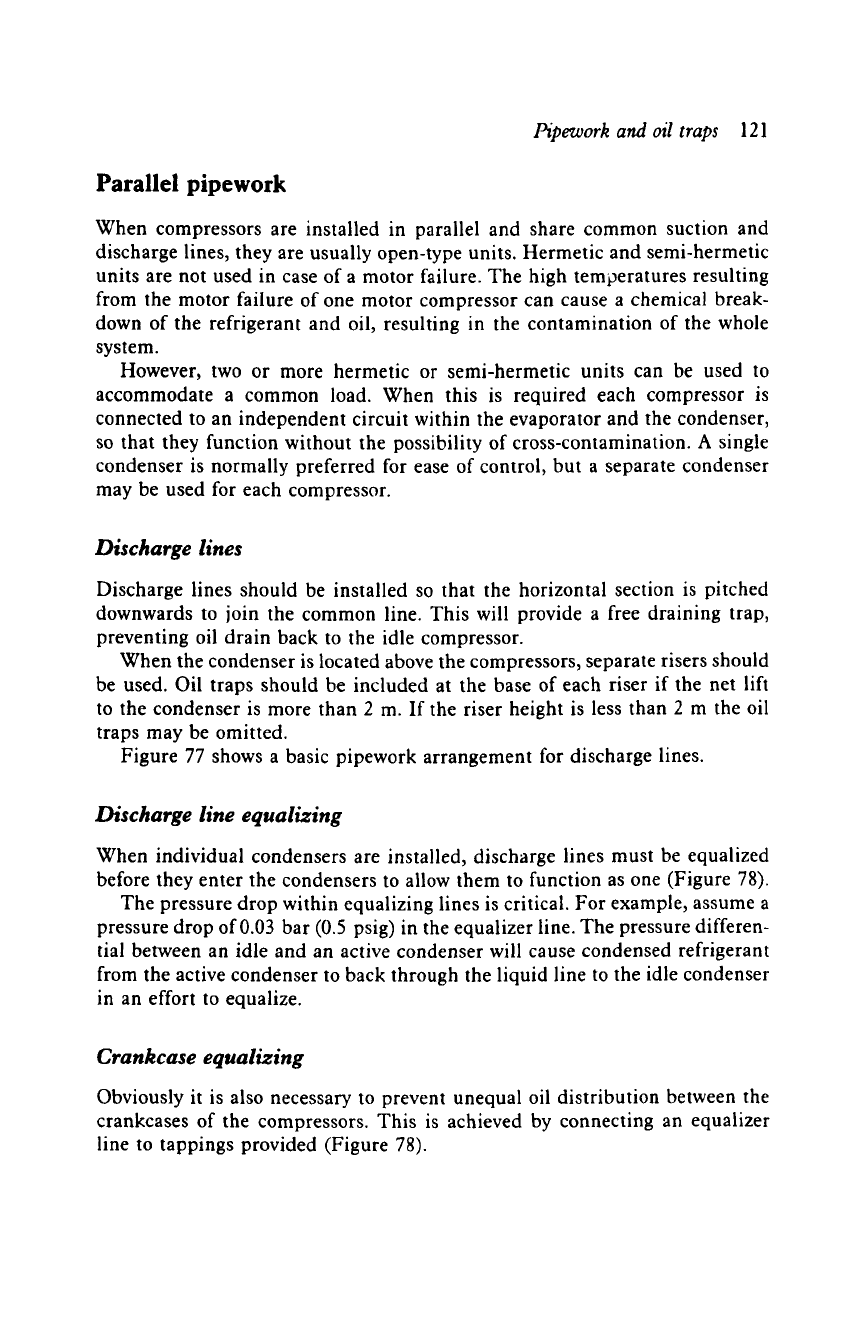
Discharge lines should be installed so that the horizontal section is pitched
downwards to join the common line. This will provide a free draining trap,
preventing oil drain back to the idle compressor.
When the condenser is located above the compressors, separate risers should
be used. Oil traps should be included at the base of each riser if the net lift
to the condenser is more than 2 m. If the riser height is less than 2 m the oil
traps may be omitted.
Figure 77 shows a basic pipework arrangement for discharge lines.
Discharge line equalizing
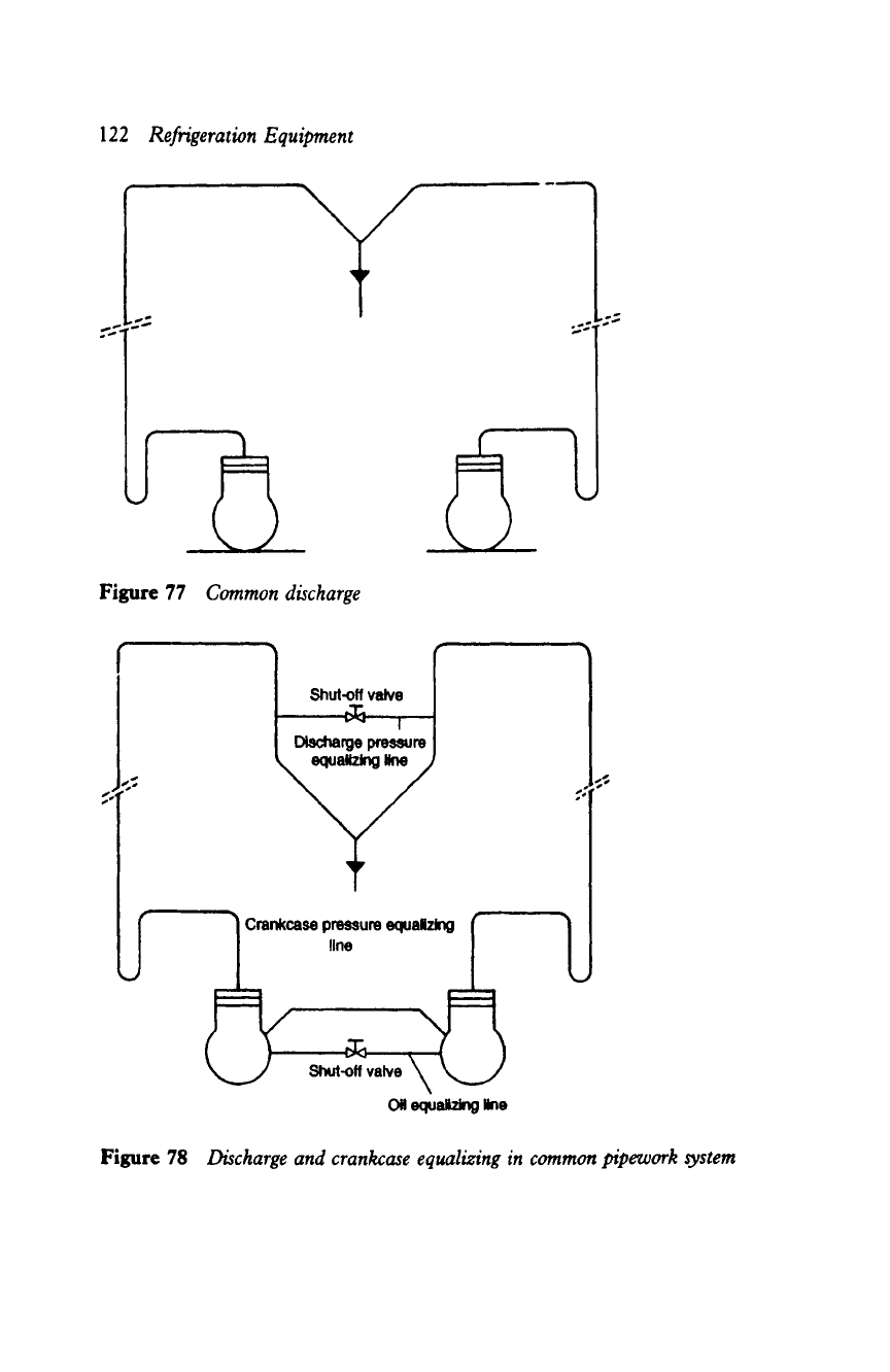
When individual condensers are installed, discharge lines must be equalized
before they enter the condensers to allow them to function as one (Figure 78).
The pressure drop within equalizing lines is critical. For example, assume a
pressure drop of 0.03 bar (0.5 psig) in the equalizer line. The pressure differen-
tial between an idle and an active condenser will cause condensed refrigerant
from the active condenser to back through the liquid line to the idle condenser
in an effort to equalize.
Crankcase equalizing
Obviously it is also necessary to prevent unequal oil distribution between the
crankcases of the compressors. This is achieved by connecting an equalizer
line to tappings provided (Figure 78).
122
Refrigeration Equipment
J,
Figure 77
Common discharge
p~
o o
|_
j
~-----~ c.-- p--. ~--.0 ff-----'U
Figure 78
Discharge and crankcase equalizing in common pipework system
Pipework and oil traps
123
The equalizer line size must be equal to the size of the tapping union. It is
also essential that the compressors are mounted on the same level or that the
oil levels are at the same height; compressor mounts can be adjusted to make
this possible.
Suction line equalizing
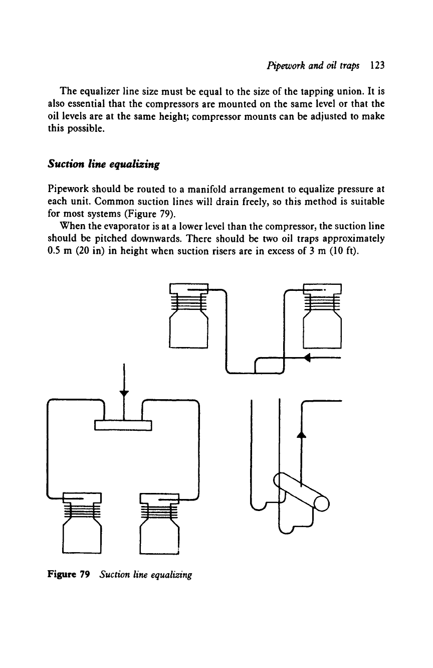
Pipework should be routed to a manifold arrangement to equalize pressure at
each unit. Common suction lines will drain freely, so this method is suitable
for most systems (Figure 79).
When the evaporator is at a lower level than the compressor, the suction line
should be pitched downwards. There should be two oil traps approximately
0.5 m (20 in) in height when suction risers are in excess of 3 m (10 ft).
i 1
Figure 79
Suction line equalizing
124
Refrigeration Equipment
Pipework assembly
Soft copper tubing up to 22 mm (7/8 in) diameter may be joined with flare
fittings or by brazing. Hard drawn copper tubing is brazed. Iron and steel
pipework is welded; cost restricts the use of welding to large industrial and
ammonia systems, and it is not described here.
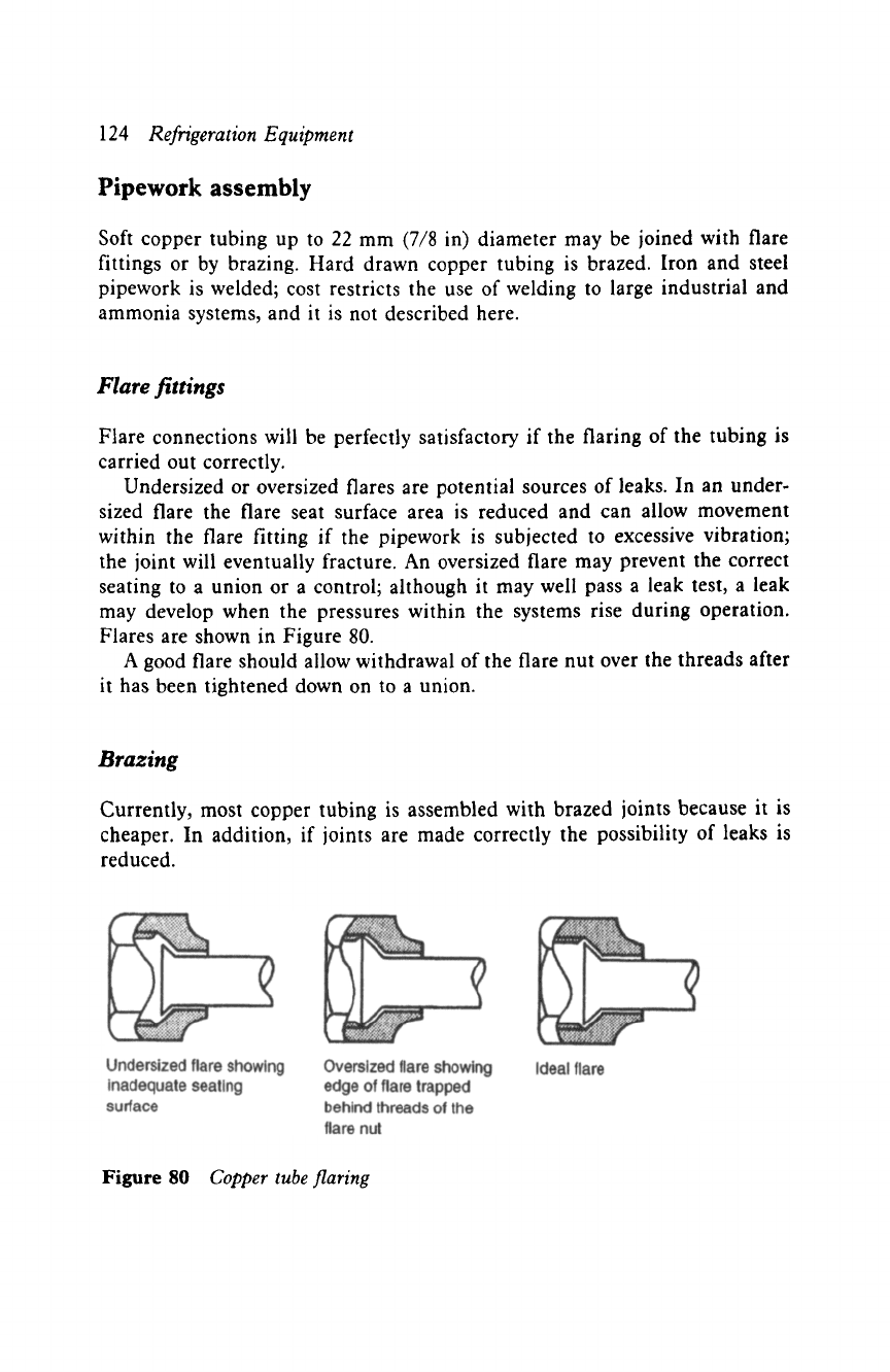
Flare fittings
Flare connections will be perfectly satisfactory if the flaring of the tubing is
carried out correctly.
Undersized or oversized flares are potential sources of leaks. In an under-
sized flare the flare seat surface area is reduced and can allow movement
within the flare fitting if the pipework is subjected to excessive vibration;
the joint will eventually fracture. An oversized flare may prevent the correct
seating to a union or a control; although it may well pass a leak test, a leak
may develop when the pressures within the systems rise during operation.
Flares are shown in Figure 80.
A good flare should allow withdrawal of the flare nut over the threads after
it has been tightened down on to a union.
Brazing
Currently, most copper tubing is assembled with brazed joints because it is
cheaper. In addition, if joints are made correctly the possibility of leaks is
reduced.
Figure
80
Copper tube flaring
Pipework and oil traps 125
Expanding
In order to make a brazed joint the tubing has to be expanded. Various tools
are available for this purpose: the punch-type expanders, swage formers used
with a flare block and spinner, and the more elaborate tube expander.
The tube expander is generally used for larger diameter tubing, which may
be hard or soft drawn copper. Hard drawn copper must be annealed before
attempting to expand the tube. Annealing is a softening process, involving
heating the tube and allowing it to cool.
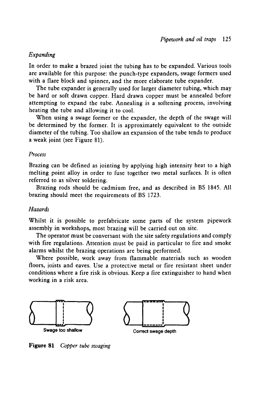
When using a swage former or the expander, the depth of the swage will
be determined by the former. It is approximately equivalent to the outside
diameter of the tubing. Too shallow an expansion of the tube tends to produce
a weak joint (see Figure 81).
Process
Brazing can be defined as jointing by applying high intensity heat to a high
melting point alloy in order to fuse together two metal surfaces. It is often
referred to as silver soldering.
Brazing rods should be cadmium free, and as described in BS 1845. All
brazing should meet the requirements of BS 1723.
Hazards
Whilst it is possible to prefabricate some parts of the system pipework
assembly in workshops, most brazing will be carried out on site.
The operator must be conversant with the site safety regulations and comply
with fire regulations. Attention must be paid in particular to fire and smoke
alarms whilst the brazing operations are being performed.
Where possible, work away from flammable materials such as wooden
floors, joists and eaves. Use a protective metal or fire resistant sheet under
conditions where a fire risk is obvious. Keep a fire extinguisher to hand when
working in a risk area.
Swage too shallow
Figure 81 Copper tube swaging
i i iii i dl- ~lIP,1~b ~ Id~6Q -- --
S '
!
!
I
!
I
!
Correct
swage depth
126
RefrigerationEquipment
The number of brazed joints should be kept to a minimum, and the bending
of copper tubing is preferred.
Preparation
All pipework and fittings to be brazed must be cleaned to remove dirt and
oxides using a fine grade steel wool. A solvent may be necessary to remove
preservative coatings from components or fittings.
Heat shields should always be used to protect areas surrounding the joint
and to concentrate heat. Protect the system components, which could suffer
damage when heat is applied, by wrapping a damp cloth around the compo-
nent close to the joint.
Ensure that all joints are a tight fit. Support the pipework before brazing
is attempted; any movement before the alloy has set can result in a leak or a
weak joint.
Equipment usage
Select the correct pressure and nozzle (Table 5). Always light the blowtorch
with a spark gun and not with matches or a cigarette lighter. Adjust the
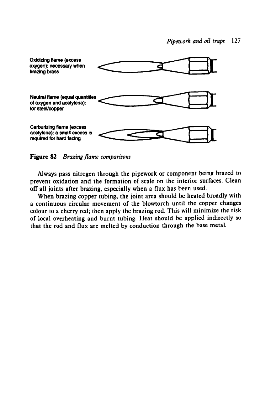
blowtorch to give the correct type of flame (see Figure 82).
Wear protective clothing and tinted goggles or glasses. Keep oxygen and
acetylene cylinders away from any heat source. Always close down the equip-
ment valves when leaving it unattended, even for a short period. Do not smoke
when brazing. Note that toxic atmospheres are created during brazing opera-
tions when cadmium, galvanized metal and paint are heated.
Table
5
Nozzle sizes
Thickness of tube wall Nozzle size
mm in
O.9 1/32 2
1.2 3/64 4
2.O 5/64 6
2.6 7/64 10
3.2 1/8 14
4.0 5/32 2O
5.0 3/16 26
6.5 1/4 36
Pipework and oil traps
127
Oxidizing flame
(excess
oxygen): necessary when
brazing
brass
Neutral
flame (equal
quantities
of oxygen and acetylene):
for
steeVcopper
Cad~urlzing flame (excess
acetylene): a small excess is
required for hard facing
Figure 82
Brazing flame comparisons
Always pass nitrogen through the pipework or component being brazed to
prevent oxidation and the formation of scale on the interior surfaces. Clean
off all joints after brazing, especially when a flux has been used.
When brazing copper tubing, the joint area should be heated broadly with
a continuous circular movement of the blowtorch until the copper changes
colour to a cherry red; then apply the brazing rod. This will minimize the risk
of local overheating and burnt tubing. Heat should be applied indirectly so
that the rod and flux are melted by conduction through the base metal.
1 1 System control valves
Crankcase pressure regulator
As a compressor starts, a heavy load is imposed on the drive motor. The
crankcase pressure will be at its highest against normal or abnormal loading.
The function of the regulator is to keep the pressure in the crankcase to
a reasonable level to protect the motor from overload. This applies when the
evaporator pressure is above normal operating pressure, for example:
1 During the initial start-up after defrosting.
2 During periods of high starting loads.
3 Under high suction pressure caused by hot gas defrosting.
4 During surges in suction pressure.
5 Under prolonged high suction pressure.
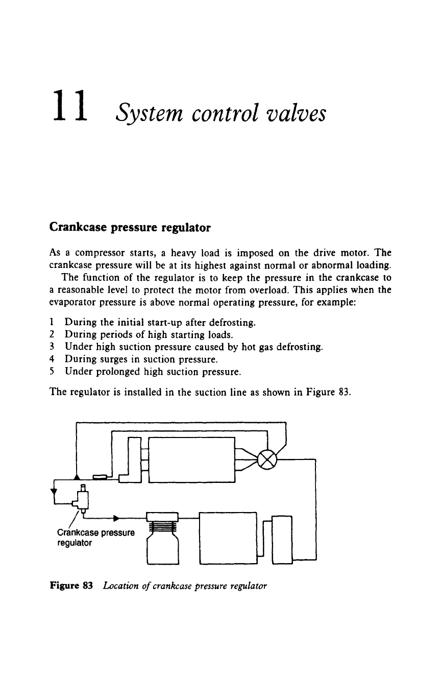
The regulator is installed in the suction line as shown in Figure 83.
Crankcase pressure
regulator
Figure 83
Location of crankcase pressure regulator
System control valves
129
As a guide, the control should be set to the following crankcase pressures:
Hermetic and semi-hermetic compressors:
Open-type compressors with standard motor:
Open-type compressors with oversized motor:
2.5 bar
3.0 bar
4.5 bar.
Final adjustments are made to make the running current conform to that
specified on the motor nameplate (running current rating).
Evaporator pressure regulator
This valve is fitted in the suction line to control the pressure in the evaporator,
to prevent it dropping below a predetermined pressure. It is used to control
the evaporating temperatures of systems such as drinking water fountains and
beverage coolers, to maintain a constant evaporator pressure/temperature and
prevent freezing.
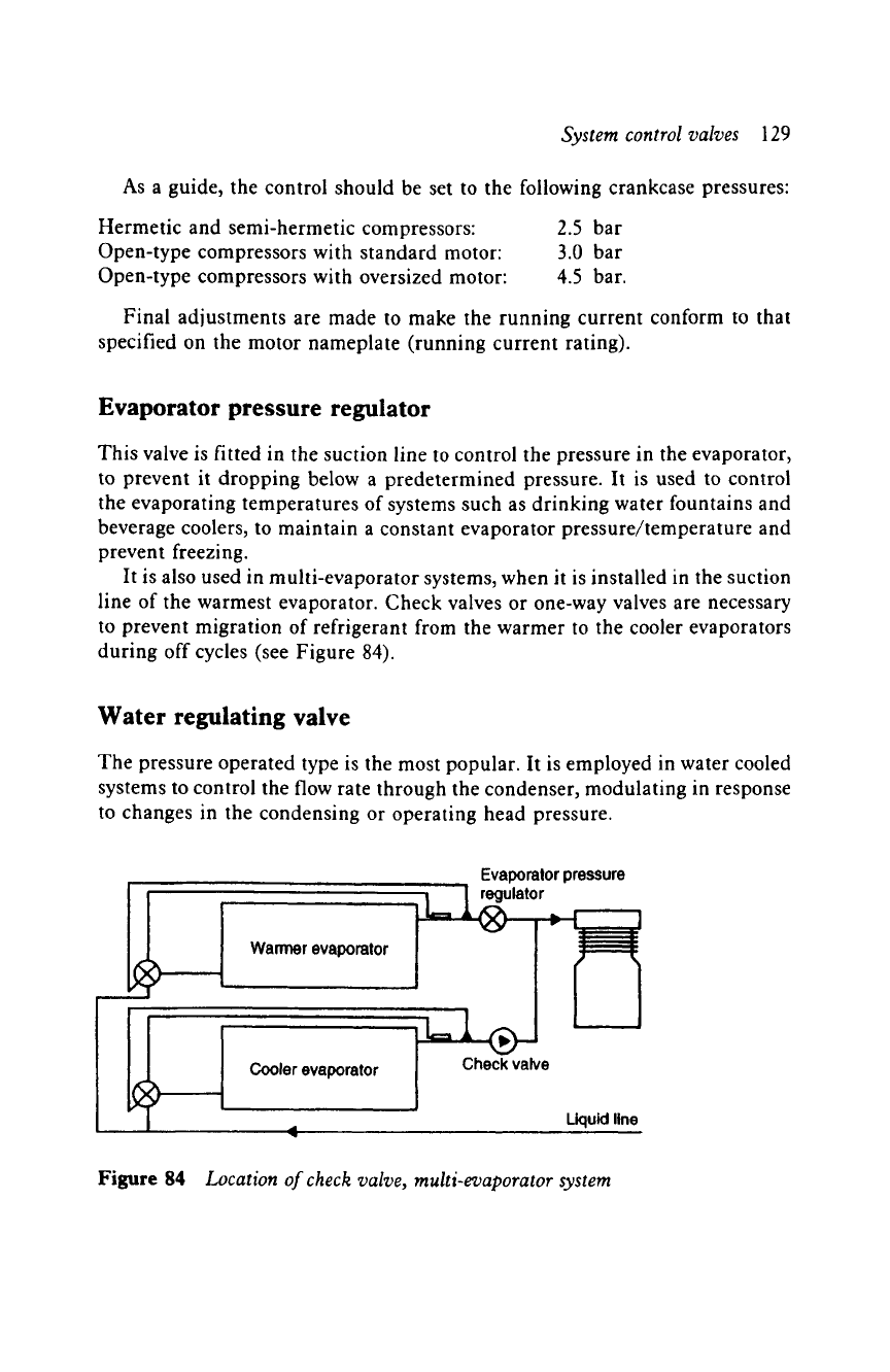
It is also used in multi-evaporator systems, when it is installed in the suction
line of the warmest evaporator. Check valves or one-way valves are necessary
to prevent migration of refrigerant from the warmer to the cooler evaporators
during off cycles (see Figure 84).
Water regulating valve
The pressure operated type is the most popular. It is employed in water cooled
systems to control the flow rate through the condenser, modulating in response
to changes in the condensing or operating head pressure.
Warmer evaporator
Evaporator pressure
regulator
i
Cooler
evaporator
Check
valve
Liquid line
Figure
84
Location of check valve, multi-evaporator system