Bryant A.C. Refrigeration equipment
Подождите немного. Документ загружается.

Im IB Im Im 11
4"
!
4tl
4ta
.UI
tm
41.11
IOta tit tie qlm
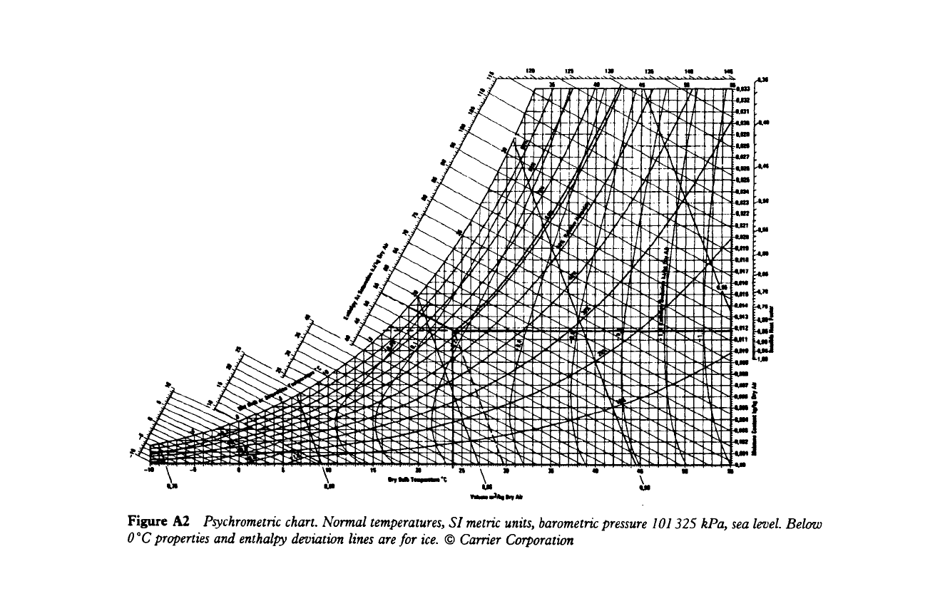
Figure A2
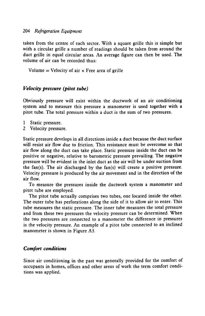
Psychrometric chart. Normal temperatures, SI metric units, barometric pressure 101325 kPa, sea level. Below
0 *C properties and enthalpy deviation lines are for ice. 9 Carrier Corporation
Appendix A 201
superimposed over the other. The first represents the dry bulb temperature,
the second the wet bulb temperature, the third the dew point temperature.
Using a sling psychrometer to determine the dry and wet bulb temperatures
provides the two factors required. Once these are established it is possible
to find the dew point temperature, moisture content, specific enthalpy and
specific volume. The lines to follow are given on Figure A1. The purpose of
the sling psychrometer is to obtain the temperature difference between the
dry and wet bulb. This temperature difference is called 'wet bulb depression'
and the wb temperature will always be the lowest.
Reading the chart
Assume that the db and wb temperatures of a sample of air are recorded as
being 24~ and 19~ respectively. If the db line is traced until it intersects
with the wb line it will be seen that this is at a point
just
above half way up
the 24 ~ line. Tracing the curve upwards to the right of this point will show
that the air sample is 61% saturated.
A horizontal trace to the left gives a dp temperature of 16.5 ~ The dotted
lines above the intersection indicate both specific enthalpy at 53.6 kJ/kg and
specific volume of 0.86 m3/kg. These values have been plotted on the psychro-
metric chart as an example.
There are many different designs of sling psychrometers available but the
basic design remains the same and when using this instrument the steps below
must be observed.
1 Ensure that the wick or gauze is adequately wetted and, if the instrument
is designed with a reservoir, that this is filled with water. Distilled water
should always be used.
2 Whirl the instrument in the air sample at a rate between 150 and 250 rpm
for a period of 15 to 25 seconds.
3 Record the db and wb temperatures, repeating step 2 three or four times
and the lowest wb temperature should be used as the recorded temperature.
4 Make a plot on the psychrometric chart to determine the relative humidity.
There are other instruments available for measuring humidity such as a
wall type hygrometer or electric hygrometer.
Just as temperature affects the comfort of a person so does relative
humidity. Low atmospheric humidity will increase the amount of electrostatic
energy in the air. An indication of this energy existing may be evident when a
person touches a metal object which is 'earthed' and a slight electric shock is
felt. A person removing clothing in a dark room may often observe minute blue
202
Refrigeration Equipment
sparks as the articles are removed. Women may find that hair styles become
unmanageable. Joints in woodwork tend to contract and become loose, cracks
may appear in woodwork over a period of time.
Humidity control
This is an important factor in air conditioning and various controls are
employed to keep the humidity of a space at a satisfactory level. One such
control is the humidistat which operates in the winter to ensure that the
system will add moisture to the air (humidify). During the summer it will
operate to remove moisture from the air (dehumidify) to maintain a fairly
constant level of humidity.
This control operates electrically to open or close solenoid valves, dampers
or air by-passes to regulate the flow of air over the system cooling coils.
The sensing element of this type of control may be of synthetic fibre or
even human hair which is very sensitive to the moisture content of the air.
The sensing element will contract or stretch to activate a switch mechanism
according to prevailing humidity conditions. The electrical supply is then
connected or disconnected to the solenoid circuits. The length of the sensing
element increases with an increase of humidity and decreases as the moisture
content of the air is reduced. When installed in an electrical circuit of an air
conditioning system it will normally override the thermostatic control when
humidity is high.
Air motion
Discomfort to occupants of a space can be attributed to improper air move-
ment even when the temperature and humidity are correctly maintained.
When cool air is circulated to a warm atmosphere heat from the atmosphere
will flow from that space, and from the objects and occupants within it. As
heat flows to the cooler air evaporation will increase, thus creating the cooling
effect. Sometimes a person exposed to atmospheric conditions will feel much
colder than the actual temperature indicates. This could be due to both rela-
tive humidity and wind velocity. Weather forecasters refer to this as the 'wind
chill factor'. Air movement is essential to suppy an adequate quantity of fresh
air to a controlled space. If the air movement is too fast it will cause draughts
and occupants within the space could feel some discomfort. If the air move-
ment is too slow then the atmosphere within the space will become stale and
lack a degree of oxygen-sufficient to cause drowsiness.
Appendix A
203
Air movement
This is defined as the distance travelled per unit of time. If the air velocity
is multiplied by the cross sectional area of a duct the volume of air flowing
through it can be calculated and this is expressed in cubic metres per second.
Measurement of air velocity
Different methods and various instruments are used to perform this task.
Installation and service engineers specializing in air conditioning should have
a sound knowledge of their construction and operation. These instruments are:
9 the rotating vane anemometer,
9 the pitot tube (velocity pressure),
9 the hot wire anemometer, and
9 the velometer.
The rotating vane anemometer, velometer and pitot tube are not accurate at
extremely low velocities. The choice of instrument will largely depend upon
site conditions, if the air is flowing into or from a duct, inside a duct or to
determine the air movement within a controlled space.
The rotating vane and hot wire anemometers should be located in the air
stream at right-angles to the flow. They should be level and allowed to remain
in the air stream for at least one minute until a constant flow of air passes over
the instrument and a true reading is attained. The rotating vane type is by
far the simplest instrument to use. The rotating speed of the air is converted
into measurement of distance by a gear mechanism. This is then indicated on
dial gauges which are an integral part of the design.
The hot wire type relies upon the cooling effect of the air flow passing over
an electrically heated wire located inside a probe. This instrument can be used
in duct air streams, open spaces and at the inlet or outlet of ductwork grilles
and diffusers.
The velometer is used in a similar manner to the rotating vane anemometer
to give direct readings of velocities. Although suitable for ducts, air flow, inlet
and outlet of system ductwork, it cannot be used for recording low velocity
air movement in a conditioned space.
When any of these instruments are used several readings should be taken
at each location, at different points of the duct system. An average figure can
then be taken and recorded.
When measurements are made at duct inlets and outlets the grille area
should be divided into 150 mm square sectors. The readings should then be
204
Refrigeration Equipment
taken from the centre of each sector. With a square grille this is simple but
with a circular grille a number of readings should be taken from around the
duct grille in equal circular areas. An average figure can then be used. The
volume of air can be recorded thus:
Volume = Velocity of air x Free area of grille
Velocity pressure (pitot tube)
Obviously pressure will exist within the ductwork of an air conditioning
system and to measure this pressure a manometer is used together with a
pitot tube. The total pressure within a duct is the sum of two pressures.
1 Static pressure.
2 Velocity pressure.
Static pressure develops in all directions inside a duct because the duct surface
will resist air flow due to friction. This resistance must be overcome so that
air flow along the duct can take place. Static pressure inside the duct can be
positive or negative, relative to barometric pressure prevailing. The negative
pressure will be evident in the inlet duct as the air will be under suction from
the fan(s). The air discharged by the fan(s) will create a positive pressure.
Velocity pressure is produced by the air movement and in the direction of the
air flow.
To measure the pressures inside the ductwork system a manometer and
pitot tube are employed.
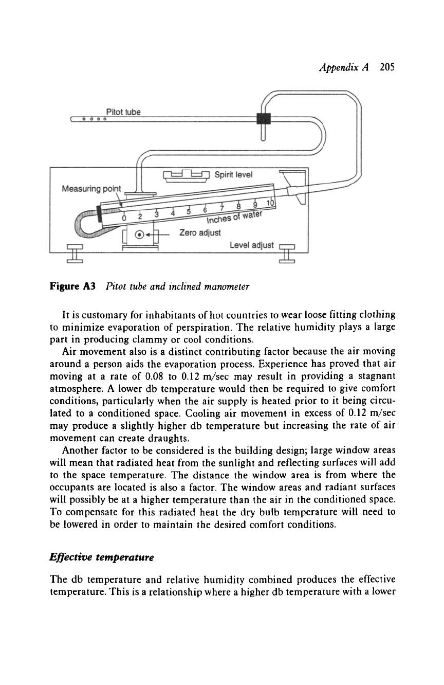
The pitot tube actually comprises two tubes, one located inside the other.
The outer tube has perforations along the side of it to allow air to enter. This
tube measures the static pressure. The inner tube measures the total pressure
and from these two pressures the velocity pressure can be determined. When
the two pressures are connected to a manometer the difference in pressures
is the velocity pressure. An example of a pitot tube connected to an inclined
manometer is shown in Figure A3.
Comfort
conditions
Since air conditioning in the past was generally provided for the comfort of
occupants in homes, offices and other areas of work the term comfort condi-
tions was applied.
Appendix A 205
Figure A3 Pitot tube and inclined manometer
It is customary for inhabitants of hot countries to wear loose fitting clothing
to minimize evaporation of perspiration. The relative humidity plays a large
part in producing clammy or cool conditions.
Air movement also is a distinct contributing factor because the air moving
around a person aids the evaporation process. Experience has proved that air
moving at a rate of 0.08 to 0.12 m/sec may result in providing a stagnant
atmosphere. A lower db temperature would then be required to give comfort
conditions, particularly when the air supply is heated prior to it being circu-
lated to a conditioned space. Cooling air movement in excess of 0.12 m/sec
may produce a slightly higher db temperature but increasing the rate of air
movement can create draughts.
Another factor to be considered is the building design; large window areas
will mean that radiated heat from the sunlight and reflecting surfaces will add
to the space temperature. The distance the window area is from where the
occupants are located is also a factor. The window areas and radiant surfaces
will possibly be at a higher temperature than the air in the conditioned space.
To compensate for this radiated heat the dry bulb temperature will need to
be lowered in order to maintain the desired comfort conditions.
Effective temperature
The db temperature and relative humidity combined produces the effective
temperature. This is a relationship where a higher db temperature with a lower
206
Refrigeration Equipment
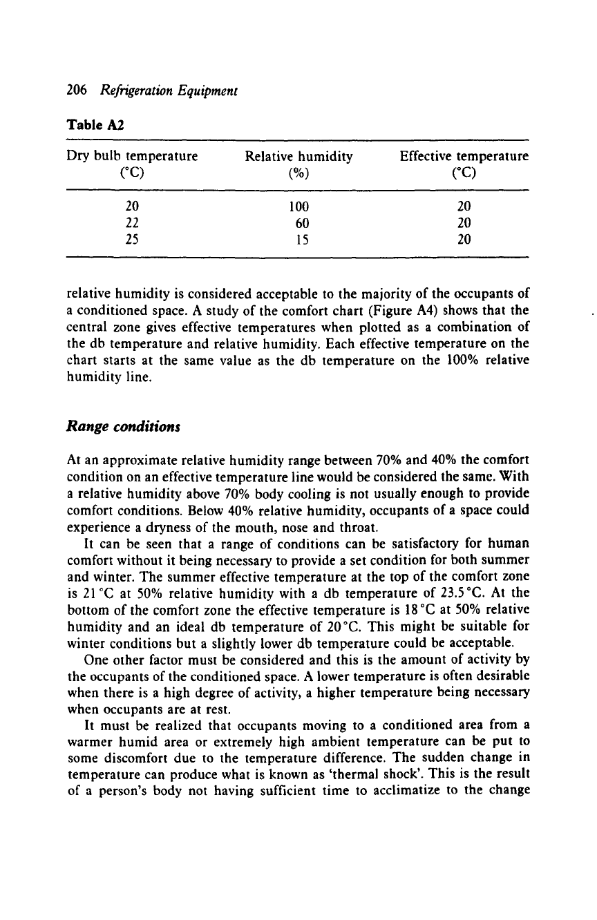
Table A2
Dry bulb temperature Relative humidity Effective temperature
(~
(%)
(~
20
100
20
22 60 20
25 15 20
relative humidity is considered acceptable to the majority of the occupants of
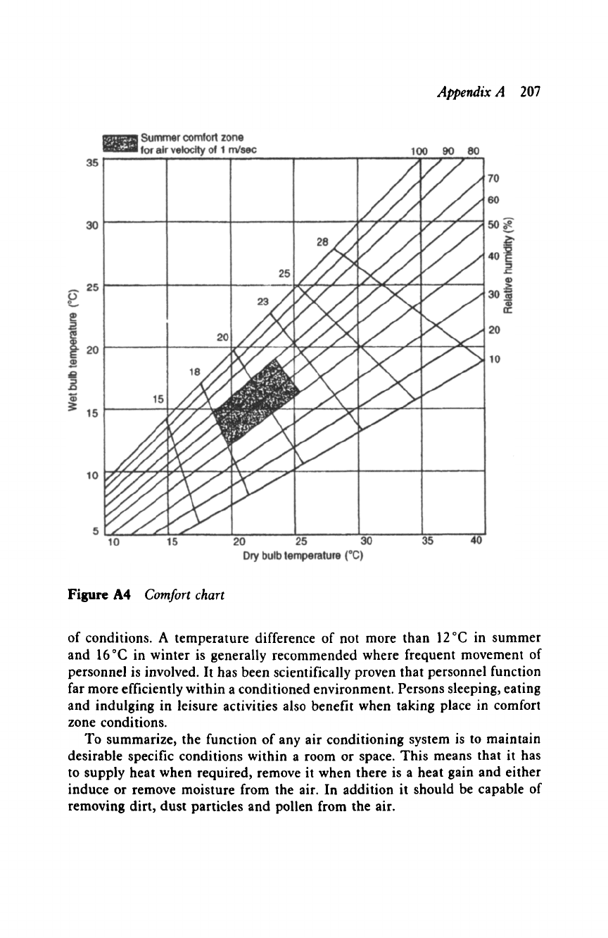
a conditioned space. A study of the comfort chart (Figure A4) shows that the
central zone gives effective temperatures when plotted as a combination of
the db temperature and relative humidity. Each effective temperature on the
chart starts at the same value as the db temperature on the 100% relative
humidity line.
Range conditions
At an approximate relative humidity range between 70% and 40% the comfort
condition on an effective temperature line would be considered the same. With
a relative humidity above 70% body cooling is not usually enough to provide
comfort conditions. Below 40% relative humidity, occupants of a space could
experience a dryness of the mouth, nose and throat.
It can be seen that a range of conditions can be satisfactory for human
comfort without it being necessary to provide a set condition for both summer
and winter. The summer effective temperature at the top of the comfort zone
is 21 ~ at 50% relative humidity with a db temperature of 23.5 ~ At the
bottom of the comfort zone the effective temperature is 18 ~ at 50% relative
humidity and an ideal db temperature of 20~ This might be suitable for
winter conditions but a slightly lower db temperature could be acceptable.
One other factor must be considered and this is the amount of activity by
the occupants of the conditioned space. A lower temperature is often desirable
when there is a high degree of activity, a higher temperature being necessary
when occupants are at rest.
It must be realized that occupants moving to a conditioned area from a
warmer humid area or extremely high ambient temperature can be put to
some discomfort due to the temperature difference. The sudden change in
temperature can produce what is known as 'thermal shock'. This is the result
of a person's body not having sufficient time to acclimatize to the change
Appendix A
207
Figure A4
Comfort chart
of conditions. A temperature difference of not more than 12~ in summer
and 16~ in winter is generally recommended where frequent movement of
personnel is involved. It has been scientifically proven that personnel function
far more efficiently within a conditioned environment. Persons sleeping, eating
and indulging in leisure activities also benefit when taking place in comfort
zone conditions.
To summarize, the function of any air conditioning system is to maintain
desirable specific conditions within a room or space. This means that it has
to supply heat when required, remove it when there is a heat gain and either
induce or remove moisture from the air. In addition it should be capable of
removing dirt, dust particles and pollen from the air.
208
Refrigeration Equipment
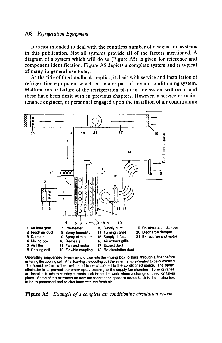
It is not intended to deal with the countless number of designs and systems
in this publication. Not all systems provide all of the factors mentioned. A
diagram of a system which will do so (Figure A5) is given for reference and
component identification. Figure A5 depicts a complete system and is typical
of many in general use today.
As the title of this handbook implies, it deals with service and installation of
refrigeration equipment which is a major part of any air conditioning system.
Malfunction or failure of the refrigeration plant in any system will occur and
these have been dealt with in previous chapters. However, a service or main-
tenance engineer, or personnel engaged upon the installion of air conditioning
I i
20 = 18 21
19 J ,e'jJ
!111 ~
o
o
1 Air inlet grille 7 Pre-heater
2 Fresh air duct
3 Damper
4 Mixing box
5 Air filter
6 Cooling coil
T
17
14
13 Supply duct
8 Spray humidifier 14 Turning vanes
9 Spray eliminator 15 Supply diffuser
10 Re-heater 16 Air extract grille
11 Fan and motor 17 Extract duct
12 Flexible coupling 18 Re-circulation duct
\
16
ur
u~
"O
|
r
O
"ID
r
._.._~ (O
19 Re-circulation damper
20 Discharge damper
21 Extract fan and motor
Operating sequence: Fresh air is drawn into the mixing box to pass through a filter before
entering the cooling coil. After leaving the cooling coil the air is then pre-heated to be humidified.
The humidified air is then re-heated to be circulated to the conditioned space. The spray
eliminator is to prevent the water spray passing to the supply fan chamber. Turning vanes
are installed to minimize eddy currents of air in the ductwork where a change of direction takes
place. Some of the extracted air from the conditioned space is routed back to the mixing box
to be re-processed and re-circulated with the fresh air.
Figure A5
Example of a complete air conditioning circulation system
Appendix A
209
systems will at some time be confronted with noise problems which do not
originate from the refrigeration plant.
Maintenance
- air flow
and noise
problems
In addition to the cooling, heating and temperature conditions consideration
has to be given to the velocity and circulation of air within a space. The
operation of fans and the condition of system ductwork is important. There
are three types of fans employed with air conditioning systems: axial flow,
radial flow and centrifugal.
9 Axial:
Air enters and leaves this type of fan axially, giving a straight-
through air flow. It is inherently noisy and seldom used for comfort air
conditioning. It is acceptable in some cases for industrial installations
where the noise factor is not so important.
9 Radial:
This type of fan can deliver a straight-through air flow being
mounted within the ductwork with the perimeter fan blades in the same
direction as the air stream. It circulates air in much the same manner as
a paddle wheel and is reasonably quiet.
9 Centrifugal: This type is most favoured for low-noise value and its ability
to perform extremely well against ductwork resistance pressures.
Ductwork
There are two types of ductwork used: round and square or rectangular. The
round duct, although it is made up of less material, is easy to manufacture
and cheaper to produce, does not take preference over the other type. This in
spite of the fact that it can handle a greater volume of air with less ductwork
area. Also, it does not present as much resistance to air flow as the square or
rectangular type.
The square or rectangular designs are selected generally because modern
building designs enable it to be easily concealed in available spaces to provide
a more attractive appearance.
Any ductwork will create resistance to air flow just as for water flowing
through a pipe. Both the duct and pipe will resist the flow.
Air passing along ductwork is subject to friction loss and this has a direct
relationship to the length and perimeter of the ductwork, but that is a ques-
tion of design. The number of direction changes, loss through cooling coils,
heater grids, filters and the condition of the duct interior surface area are all
contributing factors. It is therefore imperative that all ductwork is kept clear