Buede D.M. The Engineering Design of Systems Models and Methods
Подождите немного. Документ загружается.

process. Typical examples of controls are a blueprint and recipe instructions
(e.g., bake at 3751F for one hour, use a 9.5- by 12-inch baking pan). None-
theless, there are many times when it is very difficult to determine whether an
item is an input or control. In these cases, the decision is the author’s, with the
provision that every function must have at least one control while inputs are
optional.
Readers of an IDEF0 model are often surprised to see a function with a
control and output, but no input. This seems to suggest a counterexample to
the conservation of mass and energy in physics. Remember though that outputs
of a function in an IDEF0 model do not have to have mass or energy but can be
information. A common example of a function that can produce an output
without an input is a function that produ ces a time mark for other parts of the
system. This function receives a control whenever the tim e mark is needed and
uses its timekeeping resources to produce the time mark as an output.
3.5.3 IDEF0 Model Syntax
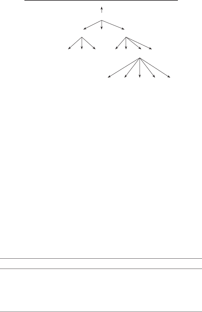
An IDEF0 model is a functional decomposition of the top-level, or A0,
function. The decomposition is a hierarchy, as shown in Figure 3.7. The
function numbers are shown on the right and the corresponding IDEF0 page
numbers are shown on the left.
The function that is being decomposed is the parent, while the functions
decomposing it are called its children. The node numbering process defines the
tree. The node numbering convention as shown in Figure 3.7 is summ arized in
Table 3.3.
Mechanism Feedback
Input Feedback
down & under
label
Control Feedback
up & over
label
down & under
label
FIGURE 3.6 Feedback semantics within an IDEF0 page.
3.5 STATIC BEHAVIORAL PROCESS MODELING WITH IDEF0 89
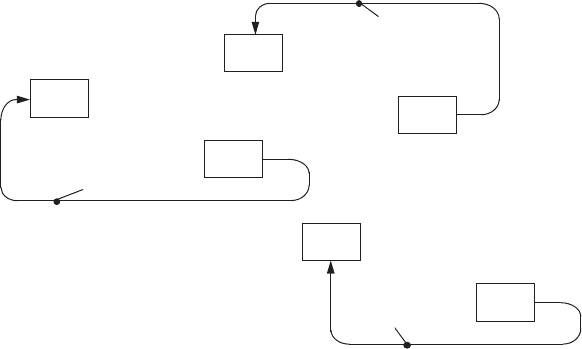
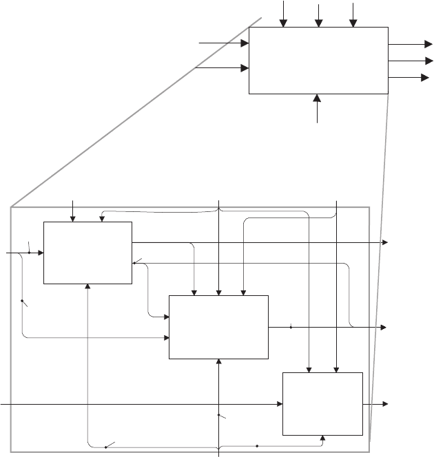
As an example of this decomposition process, the A0 page, shown in
Figure 3.8, defines the decomposition of the A0 function by three functions in
this case. Note there are two inputs, three controls, three outputs, and one
mechanism for the function A0; each of these ICOMs is given a generic label to
emphasize the conservation of ICOMs. On the decomposition of A0 into Al, A2,
and A3, there are again two external inputs, three external controls, three external
outputs, and an external mechanism. Note that I1, C2, C3, and M1 branch on
this A0 page. In addition, the joining of outputs from Al and A2 produces 02. A
number of internal items are produced, some of which branch and join.
IDEF0 models can also address the interaction of the system with other
systems. This interacti on is modeled on the A-1 page, which takes the A0
function and places it in context with other systems or organizations. This
representation is often critical to understand the relationship of the system
being addressed to the system’ s outside world and establishing the origination
of inputs and controls and the destination of outputs.
An IDEF0 mod el also has a data dictionary. An IDEF0 model should have
a glossary page that de fines the specia l words and acronyms in the labels and
Page #’s Function #’s
A-1
A-0
A0
A1, A3
A33
A0
A1 A2 A3
A11 A12 A13 A31 A32 A33 A34
A331 A332 A333 A335A334
A-0 A-12
A-11
A-13
FIGURE 3.7 IDEF0 functional decomposition.
TABLE 3.3 IDEF0 Page Hierarchy
Page Number(s) Page Content
A–1 Ancestor or External System Diagram
A–0 Context or System Function Diagram (contains A0)
A0 Level 0 Diagram with first tier functions specified
A1, A2, y Level 1 Diagrams with second tier functions specified
A11, A12, y, A21, y Level 2 Diagrams with third tier functions specified
yy
90
MODELING AND SysML MODELING
functions of the model. The data dictionary defines the arc decompositions.
These decompositions reflect the arc branches and joins in the model. The
dictionary also describes which functions use/produce which data elements.
3.5.4 IDEF0 Advanced Concepts
Advanced concepts to be discussed in this section are loops, tunneling,
functional activation rules, exit rules, and call arrows.
IDEF0 allows the use of loops to show memory storage and feedback
(see Figure 3.9). A loop is showing that there is feedback involved in the
Transform I1.1
into O1 & O2.1
as determined by
C1 & C2
using M1.1
Transform O2.1 & I1.2
into O2.2
as determined by
C2, C3 & O1
using M1.2
Transform I2
into O3
as determined by
C2 & C3
using M1.3
I1
I2
C1 C2
C3
O1
O2
O3
M1
M1.1
M1.2
M1.3
O2.1
O2.2
I1.2
I1.1
A1
A2
A3
Transform I1 & I2
into O1, O2 & O3
as determined by
C1, C2 & C3
using M1
I1
I2
C1 C2 C3
O1
O2
O3
M1
A0
FIGURE 3.8 Functional decomposition in an IDEF0 model. Showing the preservation
of inputs, controls, outputs, and mechanisms.
3.5 STATIC BEHAVIORAL PROCESS MODELING WITH IDEF0 91
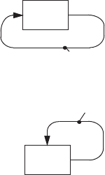
decomposition of the function shown with the loop. Usually the loop is not
needed because the feedback will be seen on the decomposition. If the function
is not going to be decomposed, it may be wise to show the loop. There are very
few instances in which a loop is appropriately shown.
Tunneling is a technique within IDEF0 to hide an input, con trol, output, or
mechanism in part of the model. The use of parentheses around either the head
or tail of an arrow depicts a tunnel in IDEF0. Parentheses around the head of
an arrow that is entering a functional box indicates that the input, control,
output, or mechanism associated with that arrow will not be seen on the
decomposition of that function; that is, the ICOM is going underground and
may or may not reappear. If the ICOM does reappear, it will have parenthe ses
around its tail to depict that it is exiting the ground. The rationale for tunneling
is that certain ICOMs are not particularly relevant for understanding the
functional model at specific levels of detail and therefore should not clutter up
these pages of the model.
Each function is activated when sufficient inputs and controls are present to
produce the relevant outputs, given those inputs and controls. This functional
activation is typically defined as a set of rules. A rule is a set of ‘‘if y, then
y‘‘statements, or pre-conditions and post-conditions. Boolean algebra is used
to specify these rules. These activation rules are embedded in each function; a
‘‘for exposition only,’’ or EEO page, is often used to articulate the activation
rules of a particular function or sets of functions.
For each function there are one or more exit criteria that determine when the
function has completed its execution. Typically, the exit criterion is associated
with the production of one or more outputs. If more than one output may be
produced by a given function, then it is critical to state the exit criteria.
The final advanced concept is that of a call arrow. A call arrow is an arrow
that breaks all of the rules of ICOMs that have been presented so far and is
seldom used in the author’s experience. The call arrow exits the bottom of an
activity’s box and points toward the bottom of the page; see FIPS Publication
label
label
Memory Feedbac
k
Memory Storage
FIGURE 3.9 Memory semantics in IDEF0.
92
MODELING AND SysML MODELING
183 [1993a] for an example. The label attached at the end of the call arrow
signifies another box that may be part of the IDEF0 model, or part of another
IDEF0 model. The call arrow is indicating that there is no decomposition of the
activity from which the call arrow is exiting, but that there is a decomposition
of the activity at the box associated with the label of the call arrow. The
advantage of the call arrow is that fewer pages need to be part of the IDEF0
model if several of the boxes have the same decomposition.
3.5.5 Systems Engineering Use of IDEF0 Models
A major emphasis in this book is the developmen t of a functional architecture
for the system that defines what functions the system must perform to trans-
form the system’s inputs into its outp uts. An IDEF0 model, minus the
mechanisms, can be used to define the functional architecture.
As part of the development of the allocated architecture the system’s
functions are allocated to the system’s components and CIs. This allocation
of functions is captured by adding the mechanisms to the functional architec-
ture, producing a description of the allocated architecture.
3.6 DYNAMIC BEHAVIORAL PROCESS MODELING WITH EFFBDS
Function flow block diagrams (FFBDs) were traditionally used in conjunction
with N
2
diagrams as the original approach to functional decomposition
in systems engineering. (In this book we are substituting IDEF0 for N
2
diagrams; N
2
diagrams are covered in Chapter 12 for the interested reader.)
Later FFBDs were extend ed and enhanced to become EFFBDs. The extended
FFBDs added more types of dynamic control logic. The enhanced FFBDs
included some items into the models for better explication and understanding.
This section first presents the full set of control logic of EFFBDs. Then shows
how the items will be added.
An EFFBD model contains all of the information in an IDEF0 model plus
sufficient information to create a unique discrete event simulation of the
dynamic behavior of the system. This is quite an added benefit over the
IDEF0 model, but it also requires additional sophistication to create. The view
adopted here is that the IDEF0 model is a stepping stone to the completed
EFFBD model for beginning systems engineers. Many experienced systems
engineers can skip the IDEF0 model and create the EFFBD directly. However
there are many other experienced systems engineers who view the IDEF0
modeling process as an important learning and communication process for the
stakeholders.
An EFFBD model has pages just as an IDEF0 model does. In fact, one
could take an IDEF0 model, add control logic to each page, and end up with an
EFFBD model. So the EFFBD model provides a hierarchical decomposition of
the system’s functions with a control structure that dictates the order in which
3.6 DYNAMIC BEHAVIORAL PROCESS MODELING WITH EFFBDS 93

the functions can be executed at each level of the decomposition. The control
structure and arrival sequence of ‘‘triggers’’ (special control inputs) determines
this order. This makes the syntax and semantics of an EFFBD model identical
to that of an IDEF0 model.
The only semantical difference between an IDEF0 and EFFBD page is that
the EFFBD has control symbols and lines that are not present in IDEF0. These
control symbols and lines will be the main emphasis of this section.
In the original, or basic, FFBD syntax there were four types of control structure
that were allowed: series, concurrent, selection, and multiple-exit function. A set
of functions defined in a series con trol structure (see Figure 3.10) must all be
executed in that order. In fact, the second function cannot begin until the first
function is finished, and so on. (Note that in the diagrams shown in this chapter
the two nodes at each end with missing center panels on the top and bottom of the
functional rectangles are functions that are outside of the decomposition of the
system function.) Control passes from left to right in FFBDs along the arc shown
from outside (depicted by a function in a box with broken top and bottom lines)
and activates the first function. When the first function has been completed (i.e.,
the function’s exit criterion has been satisfied), control passes out of the right face
of the function and into the second function, and so on. (Note that the little solid
squares in the upper left corner of functions 1 and 2 are a software construct of
CORE that indicate the function has been further decomposed.)
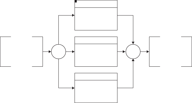
The concurrent structure (Figure 3.11) allows multiple functions to be
working in parallel, thus this structure is sometimes called ‘‘parallel.’’ However,
the concurrent structure should not be confused with the concepts of parallel in
electric circuits or redundant systems. Essentially control is activated on all
lines exiting the first AND node and control cannot be closed at the second
AND node until all functions on each control line e ntering this second AND
are completed. This control structure is almost always appropriate for the
external systems diagram; the external systems typically act concurrently with
each other and the system in which we are interested. The concurrent control
structure is also common for the first level functional decomposition of the
system function.
A selection structure and a multiple-exit function achieve essentially the
same purpose: the possibility of activating one of several functions. The
multiple-exit function (see Figure 3.12) achieves this by having a function
placed at the fork of the selection process to make the selection explicit; this is
the preferred approach to the selection structure.
Ref.
1
Perform Design
Activities
2
Perform
Integration
Activities
Ref.
FIGURE 3.10 A series function flow block diagram.
94
MODELING AND SysML MODELING
When the selection function has been completed, one of the two or more
emanating control lines is acti vated. Each control line can have zero, one, two,
or more functions on it. Additional control structures, such as concurrent, can
be placed on any of these exiting control lines. Once all of the functio ns on the
activated line have finished execution, control passes through the closing OR
node. Each exit criterion for the control lines exiting the multiple-exit function
appears has a label on the control line. (Note there is an exit criterion for every
function with only one exit but the exit criterion is not commonly shown on the
exiting control line. The engineer may add a label for this purpose if desired.)
For the selection construct, which is an exclusive or, the first OR node passes
control to one of the exiting control lines in a manner that is unspecified on the
diagram. This control line stays active until the set of functions on that control
line are completed; control then passes through the second OR node. Figure 3.9
would be a selection construct if the AND nodes were OR nodes. Since the
passing of control at the first OR node is not defined on the diagram, the author
strongly recommends the use of a multiple-exit function instead of the selection
control construct.
Additional control structures have been added to FFBDs to form what are
called enhanced FFBDs: iteration, looping, and replication. See Sidebar 3.2 for
a comparison of FFBD control constructs to structured programming.
Looping (Figure 3.12) is the repeti tion of a set of functions, based upon a
specific criterion. The loop control structure begins with an LP control
node and ends with a second LP node, as shown in Figure 3.12. The exit
criterion for a loop is shown on the line that closes the two LP nodes. In the
loop structure it is possible to exit the loop if the appropriate criterion has been
satisfied.
Ref. AND AND
1.1
Perform
System Level
Design Activities
1.2
Perform
Subsystem
Level Design ...
1.3
Perform
Component
Level Design ...
2
Perform
Integration
Activities
FIGURE 3.11 A concurrent control structure in an FFBD.
3.6 DYNAMIC BEHAVIORAL PROCESS MODELING WITH EFFBDS 95

SIDEBAR 3.2: STRUCTURED PROGRAMMING AND FFBD
CONSTRUCTS
These constructs are quite analogous to those of structured programming,
which began in the late 1950s and early 1960s with people such as Bohm,
Dijkstra, Jacopini, and Warnier [De Marco, 1979]. Initially, the goal of
structured programming was to define programming control structures
that enhanced readability and improved testing. However, the goal evolved
to define the control structures that would enable proving the correctness
of an algorithm. While correctness proofs are still a goal, it was clear to
these early investigators that program simplicity was critical. An inter-
mediate goal to a correctness proof became the identification of the
minimum set of logical constructs that would be sufficient to write any
program. Bohm and Jacopini [1966] showed that only two constructs are
necessary beyond the obvious series processing construct: ‘‘if-then-else’’
and ‘‘do-while.’’ The if-then-else construct is the equivalent of the multi-
exit function in FFBDs for situations in which a function does not need to
be repeated. For repetitive activities that fit within if-then-else, the looping
control structure is used. The iteration control structure is the same as the
do-while programming construct. The other FFBD control structures are
needed for implementation-peculiar issues of a system: Concurrent struc-
tures represent multiple resources of the system performing different
functions simultaneously, and replication represents multiple resources
performing the same function simultaneously.
Iteration is the repetition of a set of functions, as often as needed to satisfy
some domain set; this domain set must be defined based upon a number or an
interval. The iterati on control structure begins with an IT control node and
ends with a second IT node, see Figure 3.12. The domain set for the iterative
repetition is shown on the line closing the two IT nodes.
Finally, replication is the repetition of the same function concurrently using
identical resources. This repetition is shown using the stacke d paper icon; the
reader can see an example of this in the section of Chapter 12 on behavior
diagrams. This control structure is appropriate for certain physical designs and
some functional architectures.
In general FFBDs and EFFBDs do not show the inputs and outputs for
functions. However, the SysML examples of EFFBDs do show at least a subset
of the most important inputs and outputs, bringing the diagrams closer to
IDEF0 diagrams. Remember, IDEF0 has no way to capture the dynami c
information that EFFBDs do.
96 MODELING AND SysML MODELING
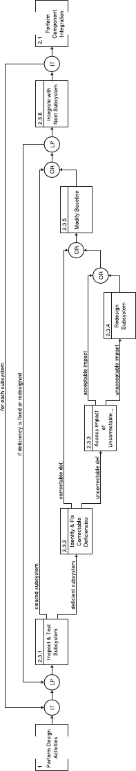
FIGURE 3.12 Selection and multiple-exit functions in an FFBD.
97
3.7 STRUCTURAL MODELING OF THE SYSTEM’S COMPONENTS
Systems engineers have been using block diagrams since the beginning of
systems engineering. However there has been no standardization of how to
construct these block diagrams, no uniform syntax and semantics. SysML has
provided a much needed syntax and semantics. A block is some element within
the spectrum from meta-system down to configurat ion item (CI). Each element
represents a set of resources (people, hardware, software, etc.) that can be used
to perform one or more functions as inputs are transformed into outputs. The
purpose of the block diagram is to display which blocks are connected to others
based on either a hierarchical relation ship or on a peer to peer basis. Block
definition diagrams represent hierarchical relationships such as how one block is
composed of several other block s. Internal block diagrams show which blocks
within a higher level block are connected to each other via interfaces.
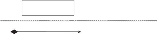
The semantics for the block definition diagram include a labeled rectangle to
define blocks, a labeled connector with a diamond on one end and an arrow
head on the other to show the hierarchical relationships. Figure 3.13 shows these
two syntactic elements. Note the full SysML semantics [Friedenthal et al., 2008]
includes many other elements, but these two are the basic ones that will be used
later in Chapter 8. Figure 3.14 shows the syntax of a block definition diagram
for the elevator system and its subsystems that was discussed in Chapter 2.
The semantics of an internal block diagram (see Figure 3.15) include a
labeled rectangle for the specific blocks that compose the higher level block that
is the subject of the diagram, small unlabeled blocks on the boundary of the
larger labeled blocks to define the connection between the block and the
interface to another block, and unlabeled lines to show the interfaces or ports
Name of Component
Name of subcomponent
Number of
multiplicities
Number of
multiplicities
Note “number of multiplicities” means the number of components that
are associated with the component on each end of the connector.
If the multiplicity is1 at either end, the multiplicity is commonly left blank.
Sample multiplicities include 0..1(zero to one), 0..*(zero to many),1..*
(one to many), 1..n (one to n),n (exactly n).
The labeled rectangle represents
a component (from meta-system
to CI) of the system with the
name of the component inside
the rectangle.
The labeled connector shows a
decomposition relationship (from
the end with the diamond to the
end with no diamond). An
abbreviated name of the
component that is lower in the
hierarchy is often shown at the
end with no diamond.
FIGURE 3.13 Semantic elements of a block definition diagram.
98
MODELING AND SysML MODELING