Buede D.M. The Engineering Design of Systems Models and Methods
Подождите немного. Документ загружается.

there are one or more cycles and the remaining nodes are part of at least one of
the cycles.
To find the semicycles in a digraph, first replace all of the directed arcs with
non-directed arcs. Then remove all nodes of degree 1. Continue this process
until there are no remaining nodes of degree 1. If there are any nodes
remaining, then there are one or more semicycles, and the remaining nodes
are part of at least one of the semicycles.
5.11 REVISITING IDEF0 DIAGRAMS
At a superficial level IDEF0 diagrams resemble the digraphs that we have been
discussing. On any IDEF0 page there are nodes, depicted as boxes, and arcs.
All of the boxes and edges are labeled as discussed earlier in this chapter.
However, we need not look too de ep to see some major discrepancies between
digraphs and a page of an IDEF0 model. The inputs, controls, outputs, and
mechanisms (ICOMs) coming from external sources to the page are not nodes
but label s on the edges. These edges, associated with the external ICOMs, do
not have a node at one of their ends; this never happened in a digraph since an
edge depicted a relation between two elements of a set A and all of the elements
of A were shown in the graph.
As mentioned in the previous paragraph, each edge on the IDEF0 diagram is
labeled. While there can be labels on the edges in digraphs, all of the digraphs
presented in this chapter had none. In a digraph each edge represents the fact
that a single relation exists between each pair of connected nodes, aRb.
Each node in the IDEF0 diagram is called a function and is named
consistently with our understanding of a function, namely a transformation.
Yet, digraphs represent a specific relation, which may be a mathematical
function if certain conditions are satisfied (see Chapter 4). The relation, or
function, in a digraph is represented by the edges, not the nodes.
At an even deeper level, each label on the edge of an IDEF0 arrow actually
represents a set of possible items that can become an input, control, or output
of the relevant function. All of the possible inputs and controls entering a
function must then be represented by n-tuple of the Cartesian product across all
input and control arrows entering that function. Similarly, the Cartesian
product represents all possible outputs of a function across all output arrows
exiting a function. So, there are, in fact , many important differences between a
digraph and a page of an IDEF0 diagram.
A number of people have attempted to transform an IDEF 0 model into a
bipartite graph. The first step is to turn the arc labels into nodes of a second
type, say circles. The IDEF0 diagram (without mechanisms) in the top of
Figure 5.18 is converted into a bipartite graph in the bottom of Figure 5.18.
Each label is replaced by a circular node. Each external label is connected by
the edge entering or leaving the appropriate function. The new nodes for I12
and C12 are now connected by two edges; one going into the new node and one
5.11 REVISITING IDEF0 DIAGRAMS 139
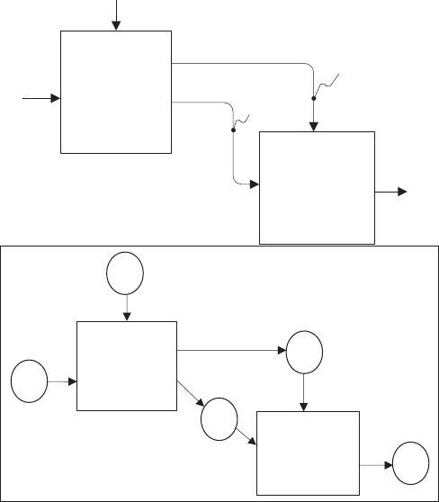
coming out of the new node. We have now satisfied the basic requirements of a
bipartite graph; there are two types of node s and no edge connects two nodes of
the same type. There are, in essence, two types of edges; those that connect
boxes to circles (outputs of the function in the box) and those that connect
circles to boxes (inputs to the function in the box).
However, there are two remaining problems. First, IDEF0 differentiates
between arcs entering a function from the top and left. There is no provision for
such different iation in digraphs. Other process modeling techniques in Chapter
12 do not differentiate between inputs and controls; it is necessary to drop this
distinction between inputs and controls, as is done in Petri nets, which is the
only graph-theoretic modeling tool discussed in Chapter 12.
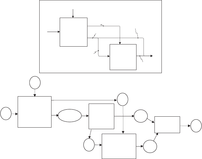
Second, there is a problem with branches and joins. There is no analogous
construct in graph theory. To solve this problem a function must be inserted at
each branch to accomplish a divide or copy, and at each join to accomplish a
paste. See Figure 5.19.
I1
C1
O1
Transform I1
into I12 and
C12 in
accordance
with C1
A1
Transform I12
into O1 in
accordance
with C12
A2
I12
C12
I1
C1
O1
A1
Transform I1
into I12 and C12
in accordance
with C1
A2
Transform I12
into O1 in
accordance with
C12
I12
C12
FIGURE 5.18 ICOM labels converted to nodes.
140
GRAPHS AND DIRECTED GRAPHS (DIGRAPHS)
With all of these workarounds, IDEF0 remains a static snapshot of a
dynamic process. There are potentially infinite dynamic models that can be
created from each IDEF0 model. The information that separates the proper
dynamic model from the rest of the possible dynamic models is not in the IDEF0
model but remains in the mental model of the creator of the IDEF0 model. If a
team (which is most common) creates the IDEF0 model, it is possible, even
likely, that each team member has a mental model of a different dynamic
representation of the static IDEF0 model. This is why creating a dynamic model
from the IDEF0 representation is so important; the communication process
among the systems engineering team must be carried as far as possible.
5.12 SUMMARY
A graph consists of a set of nodes and a set of edges. The edges define a relation
over the set of nodes. The relation can require an order of the nodes in which
case the edges are directed; directed graphs are the most applied in the
engineering of systems. Bipartite graphs are a special form of a directed graph
in which there are two types of nodes, and the edges cannot connect nodes that
are the same type.
I1
C1
O1
Transform I1
into I12 and
C12 in
accordance
with C1
A1
Transform I12
into O1 in
accordance
with C12
A2
C12
O1a
I12
I12 & O1a
O1b
I1
C1
O1
A1
Transform I1
into I12&O1a
C12 in
accordance
with C1
A2
Transform I12
into O1b in
accordance with
C12
I12
C12
A4
Paste O1a
together with
O1b
A3
Divide
I12&O1 a
into I12
and O1a
I12&O1a
O1a
O1b
FIGURE 5.19 IDEF0 page with divide and paste functions added.
5.12 SUMMARY 141
Sequences of nodes in a graph can be defined by the terms walk, path, trail,
circuit, and cycle. Graphs can be connected or disconnected; there are variations
of connectedness, ranging from weakly to strongly. Nodes that are not adjacent
to each other in a graph can be reachable via a path in the graph. This notion of
reachability can be critical if attaining some output requires the execution of a set
of functions, but the set of functions is not part of a reachable set.
The properties of reflexivity, irreflexivity, symmetry, antisymmetry, asym-
metry, transitivity, and intransitivity were defined in Chapter 4 and then
redefined in terms of graphs in this chapter. Visualizing these relations provides
a much greater understanding of their meanin g and ability to detect their
absence or presence in a graph.
Partial orders of the elements of a set were defined as alternative orders of
the nodes based upon the relation defined over the nodes. The Hasse diagram
was defined and illustrated for finding the partial order on the set and then
enumerating the possible partial orders.
Trees and several variations of trees were introduced as a special form of a
graph. A directed tree describes the notion of a hierarchical decomposition.
Hierarchies of requirements, functions, and components were discussed in
Chapter 2 and will be revis ited in Chapters 6 through 11. These hierarchies
must be partiti ons (as defined in Chapter 4) and can be represented as directed
trees.
Finally the IDEF0 process modeling technique was revisited and discussed
in terms of mathematical graph theory. The reasons why an IDEF0 model is
not a directed graph were discussed, as well as the difficulty associated with
turning an IDEF0 model into a graph.
PROBLEMS
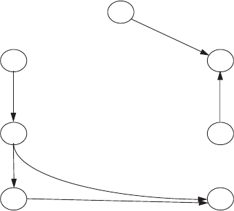
5.1 For the following graph , G
1
:
b
a
f
d
g
e
c
142 GRAPHS AND DIRECTED GRAPHS (DIGRAPHS)
a. Find |V(G
1
)| and |E(G
1
)|.
b. Write the relation depicted by G
1
as a set of ordered pairs.
c. Define the adjacency matrix of G
1
.
d. What is the out degree of each node of G
1
? What is the in degree of
each node of G
1
?
e. Could G
1
be a bipartite graph? If no, why? If yes, what is the partition
into two subsets of nodes that makes this a bipartite graph?
f. Is the relation depicted here reflexive? irreflexive? symmetric? anti-
symmetric? asymmetric? transitive? intransitive?
g. What arcs (if any) would you have to add to this relation to make it
transitive
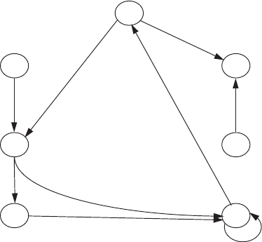
5.2 For the following graph, G
2
:
b
a
f
d
g
e
c
a. Write the relation depicted by G
2
as a set of ordered pairs.
b. Define the adjacency matrix of G
2
.
c. Could G
2
be a bipartite graph? If no, why? If yes, what is the partition
into two subsets of nodes that makes this a bipartite graph?
d. *Is there a cycle in G
2
? How many?
e. *Is there a semi cycle in G
2
? Which nodes are included?
f. Is the relation depicted here reflexive? irreflexive? symmetric? anti-
symmetric? asymmetric? transitive? intransitive?
g. What arcs (if any) would you have to add to this relation to make it
transitive?
h. *Delete the arc from g to a and draw a Hasse diagram for G
2
. Why
must we delete the arc from g to a before we can draw a Hasse
* Advanced assignment.
PROBLEMS 143

diagram? Define at least 10 different node orderings consistent with
this Hasse diagram.
5.3
a. Develop a directed graph for the relation ‘‘_____ has defeated ____.’’
using the following won/lost records of the two 1993 Super Bowl
teams. Create a single node for each team and an arc for each defeat.
Note this will be a multigraph.
Buffalo Bills Dallas Cowboys (DC)
(BB) Schedule
Schedule
BB 38 NEP 14 DC 16 WR 35
BB 13 DC 10
BB 13 MD 22 DC 17 PC 10
BB 17 NYG 14 DC 36 GBP 14
BB 35 HO 7 DC 27 IC 3
BB 19 NYJ 10 DC 26 SFF 17
BB 24 WR 10 DC 23 PE 10
BB 0 PS 23DC20PC 15
BB 13 NEP 10 DC 31 NYG 9
BB 23 IC 9 DC 14 AF 27
BB 7 KCC 23 DC 14 MD 16
BB 24 LAR 25 DC 23 PE 17
BB 10 PE 7 DC 37 MV 20
BB 47 MD 34 DC 28 NYJ 7
BB 16 NYJ 14 DC 38 WR 3
BB 30 IC 10 DC 16 NYG 13
BB 29 LAR 23 DC 27 GBP 17
BB 30 KCC 13 DC 38 SFF 21
SUPER BB 13 DC 30
b. Is this directed graph reflexive? irreflexive? trans itive? asymmetric?
c. *There will be cycles in the graph created in part (a). Break these cycles
by eliminating arcs in favor of the two Super Bowl teams; that is, if
there is a cycle between a Super Bowl team and another team,
eliminate the arc showing that the Super Bowl team was defeated by
* Advanced assignment.
144 GRAPHS AND DIRECTED GRAPHS (DIGRAPHS)

the other team. Assume the resulting relation is a partial order and
draw a Hasse diagram of the relation.
5.4 For the following adjacency matrix:
abcdefgh i
a 010000000
b 001010000
c 000100000
d 100000000
e 000000001
f 000000001
g 000001000
h 000000100
i 000000010
a. Draw the graphical representation, G
4
, that is defined by the adjacency
matrix.
b. Find |V(G
4
)| and |E(G
4
)|.
c. Write the relation depicted by G
4
as a set of ordered pairs.
d. What is the out degree of each node of G
4
? What is the in degree each
node of G
4
?
e. Could G
4
be a bipartite graph? If no, why? If yes, what is the partition
into two subsets of the nodes that makes G
4
a bipartite graph?
f. Which of the seven properties (reflexive, irre flexive, transitive, intran-
sitive, symmetric, asymmetric, antisymmetric) does this relation satisfy
5.5 *Drop the arc from b to c in Figure 5.15 and draw a Hasse diagram for
the resulting graph. How many orderings of the nodes in the digraph are
consistent with this Hasse diagram?
5.6 There are three families defined by the sets A, B, and C; each family has
a dad, mom, and three kids:
A = {Dad, Mom, Doris, Bill, Tom}
B = {Dad, Mom, Doris, Daisy, Debbie}
C = {Dad, Mom, Bill, Bob, Biff}
Consider the relations ‘‘is the spouse of,’’ ‘‘is the brother of,’’ and ‘‘is the
blood relative of.’’ (Hints: I am not the brother of myself. Two people are
blood relatives if they share the blood of a common ancestor, who may or
may not be part of sets A, B,orC. I am the blood relative of myself.)
* Advanced assignment.
PROBLEMS 145
Create a digraph for each of the three relations on each of the three sets.
Identify which of these relations satisfy which of the seven properties of
unary relations for each of the three sets by placing a yes or no in the empty
cells of the following table .
Reflexive
Irreflexive
Symmetric
Anti-symmetric
Asymmetric
Transitive
Intransitive
‘‘is the spouse of ’’ on A
‘‘is the brother of ’’ on A
‘‘is the blood relative of ’’ on A
‘‘is the spouse of ’’ on B
‘‘is the brother of ’’ on B
‘‘is the blood relative of ’’ on B
‘‘is the spouse of ’’ on C
‘‘is the brother of ’’ on C
‘‘is the blood relative of ’’ on C
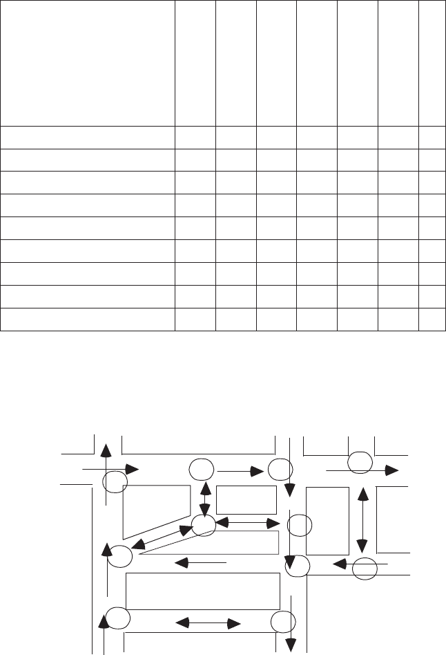
5.7 A city street snapshot is shown in the figure. Note there are streets with
arcs on them indicating one-way streets. The streets with double-headed
arcs are two-way streets. There are 11 intersections, labeled 1 through 11.
1
2
3
4
5
6
8
7
9
10
11
146 GRAPHS AND DIRECTED GRAPHS (DIGRAPHS)
a. Draw a directed graph that represents this street system. (Hint: Use a
node to represent street intersections.)
b. Is this digraph quasi-strongly connected? If not, what is the minimum
number of arcs that must be added and what nodes must they connect
to make it quasi-strongly connected? If yes, why?
c. If you think the digraph in part (a) is quasi-strongly connected, draw a
directed spanning tree for it. If you do not think the digraph in part (a)
is quasi-strongly connected, add arcs so that it is and then draw a
directed spanning tree for it.
d. What is the height of the tree that you have drawn?
5.8 For the set of all possible relations, create a partition using combina-
tions of the properties symmetric, antisymmetric, and asymmetric
where each subset in the partition cannot be empty. As an example, a
partition of all relations using the properties reflexive and irre flexive
would be: (reflexive relations), (irreflexive relations), (relations that
are neither reflexive nor irreflexive). Note the subset of relations that
are both reflexive and irreflexive is left out because this combination is
impossible.
5.9 Consider an IDEF0 model in which the function A0 has two inputs (I
1
and I
2
), three controls (C
1
,C
2
,andC
3
) and three outputs (O
1
,O
2
, and
O
3
). The IDEF0 function, A0, can be considered a relation that maps
elements of D =(I
1
XI
2
XC
1
XC
2
XC
3
) into elements of P =(O
1
XO
2
XO
3
). The 5-tuple for inputs and controls to A0 and the 3-tuple for
outputs are used because each inpu t, control, and output represents a set
of possible inputs, controls, or outputs, respectively. The n-tuples define
all possible combinations of inputs and outputs, respectively. Under
what restrictions is A0 a function? Why?
PROBLEMS 147

Part 2
Design and Integration