Buede D.M. The Engineering Design of Systems Models and Methods
Подождите немного. Документ загружается.


Chapter 11
Integration and Qualification
11.1 INTRODUCTION
Integration is the process of assembling the system from its components, which
must be assembled from their configuration items (CIs). Qualification is the
process of verifying and validating the system design and then obtaining the
stakeholders’ acceptance of the design. Recall that verification is the determi-
nation that the system was built right while validation determines that the
right system was built. Both of these activities are conducted by the systems
engineering team as pa rt of the development process, primarily during
integration. Validation has critical early elements (conceptual, design require-
ments, and validity) that are completed during the design phase. The system
that is used to qualify the system being designed must be built for that purpose.
So while the operational system is being designed, the qualification system for
the operational system is also being designe d and integrated. The operational
phase for this qualification system is during integration and qualification.
Also keep in mind that other systems are being developed concurrently
with the operational system, namely, some or all of the manufacturing,
deployment, training, refinement, and retirement systems. Each of these also
has a qualification system.
The terms testing and qualification are used interchangeably in parts of this
chapter. The word testing is associated with the key words of acceptance,
validation, and verification by most systems engineer s. However, the process of
acceptance, validation, and verification comprise what is being called qualifica-
tion in this chapter. The confusing usage arises when an instrumented test is
mentioned as one of four methods that comprise qualification (testing), and the
other three methods do not contain the word test: inspection, demonstration,
The Engineering Design of Systems: Models and Methods, Second Edition. By Dennis M. Buede
Copyright
r 2009 John Wiley & Sons, Inc.
341
and analysis and simulation. In fact, these three methods are forms of test.
The word qualification is used in this chapter as often as possible to mean the
process that comprises acceptance, validation, and verification testing. The
word testing will be used with these three terms but is meant to be associated
with the methods used in the qualification process during integration.
This chapter begins by providing a detailed definition of the elements of
qualification: acceptance testing, validation, and verification. Section 11.3
discusses the concept of integration since qualification takes place as integration
is progressing; alternate processes for integration are discussed in Section 11.4.
Then qualification is described in detail, beginning with planning and proceeding
to a detailed discussion of qualification methods. Special topics in acceptance
testing are described in Section 11.7.
The exit criterion for integration and qualification is acceptance of the design
by the stakeholders. This is often done conditionally, that is, with the provision
that certain system elements be revised to enable greater cost-effectiveness
during operation.
11.2 DISTINCTIONS AMONG ACCEPTANCE, VALIDATION
AND VERIFICATION TESTING
In Chapter 1 the concepts of verification, validation, and acceptance were
introduced. (Grady [1997] pr ovides additional detail on the distinctions being
discussed here.) Acceptance is a stakeholder function for agreeing that the
designed system, as tested or otherwise evaluated by the stakeholders, is
acceptable. As such acceptance is driven by the stakeholders, with the knowl-
edge of the results of validation and verification activities that have preceded it.
See Figure 11.1.
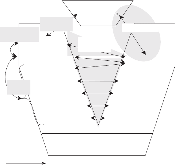
Validation is the process of determining that the systems engineering process
has produced the right system, based upon the needs expressed by the
stakeholder. Validation is carried out by the systems engineers, based upon
what they believe the stakeholders’ ne eds to be. The most reliable and early
statement of the stakeholders’ needs is the operational concept. Therefore
operational validity is the matching of the capabilities of the designed system to
the operational concept; this naturally occurs late in the integration phase after
the designed system has been verified. However, conceptual validity, require-
ments validity, and design validity are important aspects of validity and need to
be addressed early in the design phase. Conceptual, requirements, and design
validity are called early validation, the determination that the right problem is
being defin ed at the current level of abstraction, given the validity of the
problem definition at a higher level of abstraction.
Conceptual validity is the correspondence between the stakeholders’ needs
and the operational concept. Conceptual validity needs to be established at the
outset of the design process via interactions among the systems engineer s and
the stakeholders; however, the systems engineer cannot assume that once
342 INTEGRATION AND QUALIFICATION
established there is no more work to be done. Stakeholders’ needs change and
the operational concept must change with those needs. Note operational
validity only makes sense if conceptual validity has been established. If both
conceptual and operational validity are solid, then the stakeholders’ acceptance
should be nearly guaranteed.
Requirements validity is the correspondence between the operational concept
and the stakeholders’ requirements. In requirements validity the operational
concept is assumed to be an accurate reflection of the stakehol ders’ needs; the
validation occurs by establishing that the stakeholders’ requirements have
neither introduced new issues nor left issues out of the operation al concept,
thus causing the design of a different system than envisioned in the operational
concept. But recall that the operational concept and stakeholders’ requirements
should be stated in design independent terms, making this task of requirements
validity quite difficult. Elements of requirements validity are ensuring there are
input/output requirements for all of the inputs and outpu ts in the operational
concept; that every objective in the objectives hierarchy has a performance
requirement in the StkhldrsRD; that every external interface to the system
has been considered for an external interface requirement; and so forth.
Design
Engineering
Systems Engineering
SE Vee
Time
Operational Concept
Stakeholders’
Requirements
System Requirements
Element Specs
Segment Specs
Component Specs
CI Specs
System Delivered
Elements Delivered
Segments Delivered
Components Delivered
CIs Delivered
Operational
Validity
Stakeholders’
Needs
Acceptability
Developmental
Verification
Conceptual
Validity
Design
Validity
Requirements
Validity
FIGURE 11.1 Verification, validation, and acceptance.
11.2 DISTINCTIONS AMONG ACCEPTANCE, VALIDATION AND VERIFICATION TESTING 343
The external systems diagram and objectives hierarchy (discussed in Chapter 6)
are key tools for establishing this requirements validity. In addition, inter-
mediate products such as a data model that relates the inputs to and outputs
from the system in the operational concept to the aggregate inputs and outputs
of the system in the external systems diagram can and should be developed to
support requirements validation. At a higher level of abstraction, the systems
engineers should be asking ‘‘Can we get something we do not want even though
these requirements stating our needs are met?’’ In addition they should ask
‘‘Can we get what we want (the problem solved) without getting what we have
asked for in the requirements?’’ If either of these questions can be answered
positively, there is more work to do on the requirements.
Design validity assumes that the Stakeholders’ Requirements Document
(StkhldrsRD) is a valid statement of the stakeholders’ needs and addresses the
congruence between the StkhldrsRD and the derived requirements. The derived
requirements begin with the Systems Requirements Document (SysRD), evolve
to subsystem and component specifications, and culminate in CI specifications.
In Chapter 9 three techniques for flowdown or derivation of requirements were
discussed: apportionment, equivalence, and synthesis. Establishing design
validity for apportionment and equivalence is straightforward. Design valida-
tion when synthesis is involved, on the other hand , requires establishing the
validity of the models used to complete flowdown via synthesis. These models
are used to transform requirements on one or more variables to requirements
on parameters that have a functional relationship with these variables. A
common cause for failure in this synthesis process is that the models being used
were valid in previous engineering efforts but are not valid for the current
system; yet the validity of the models from previous developments of similar
systems is assumed to pertain to the current development. Petroski [1994]
provides extensive evidence of such failures in structural design engineering;
failures of bridges are highlighted in particular. The designers forgot the lessons
of past failure modes and built bridges that were extrapolations of previous
efforts: Extrapolations that were not justified based upon modeling assump-
tions that were not examined in sufficient detail.
Conceptual requirements and design validity are the province of the
systems engineering team and must be undertaken very seriously to ensure
that the requirements development process does not redefine the problem being
solved. There are two chains that must be strong ; see Figure 11.2. The first
chain consists of conceptual validity, operational validity, and acceptance
testing. Requirements validity, design validity, verification, and operational
validity comprise the second chain. Each of these chains is only as strong as the
weakest link.
Verification is the matching of CIs, components, subsystems, and the syst em
to their corresponding requirements to e nsure that each has been built right.
This process of design verification is also carried out by the systems engineering
team to ensure that the design problem defined in conjunction with the
stakeholders is being solved appropriately. In order for verification to be
344 INTEGRATION AND QUALIFICATION
successful, the originating and derived requirements must be testable; that is,
the requirements must be single statements that are unambiguous, under-
standable, and verifiable (see Chapter 6).
Verification begins in the design phase with the definition of the derived
requirements and becomes the focus of activity early in the integrati on phase
when the systems engineers ca n match the derived requirements to the
capabilities of the CIs and the components. However, the design of the test
system to achieve this verification must occur in the design phase of the system.
It is a misconception to picture verification as beginning and ending before
validation, which begins and ends before acceptance testing. In fact, as can be
seen in Figure 11.1, validation has to begin with the definition of requirements
to ensure that there is conceptual validity between the operational concept and
the stakeholders’ needs. Requirements vali dity also begins almost immediately
to address the congruence between the stakeholders’ requirement s and the
operational concept. Finally, design validity addresses the consistency and
Design
Engineering
Systems Engineering
SE Vee
Time
Operational
Concept
Stakeholders’
Requirements
System Requirements
Element Specs
Component Specs
CI Specs
System Delivered
Elements Delivered
Components Delivered
CIs Delivered
Operational
Stakeholders’
Needs
Developmental
Verification
High Level Chain
Low
Level
Chain
Requirements
Validity
Design
Validity
Validity
Segment Specs
Segments Delivered
Acceptability
Conceptual
Validity
FIGURE 11.2 Two qualification chains. The high level chain consists of conceptual
validity, operational validity, and acceptability. The low level chain consists of design
validity, requirements validity, developmental verification, and operational validity.
11.2 DISTINCTIONS AMONG ACCEPTANCE, VALIDATION AND VERIFICATION TESTING 345
congruence between stakeholders’ requirements and derived requirements. For
example, does every input and output to the system have at least one
requirement associated with it? Does the system have all of the system-wi de
requirements it should have? Before operational validation can begin, design of
a qualification system must occur. The IDEFO (Integrated Definition for
Function Modeling) representation in Figure 11.3 of early validation, verific a-
tion, operational validation, and acceptance testing suggests the most likely
sequential ordering. In practice, though, there is substantial concurrency
involving these processes, making the results even more difficult to get right.
Finally, in order for the acceptance test to be successful, there must be clear
agreement between the acceptance thresholds and the early design documents
of the operational concept and stakeholders’ requirements. Therefore, design of
the acceptance test must begin early enough to enable both conceptual and
design validity.
Successful integration relies critically on the complete and consistent
development of stakeholders’ requirements, the proper flowdown of stake-
holders’ requirements into derived requirements and tracing of requirements to
functions and components/CIs, and the analysis of system performance and
cost in light of the stakeholders’ fundamental objectives. These are design
activities associated with the system. The development of test requirements,
including the verification, validation, and acceptance test plans, initializes
integration and helps formalize the design process.
11.3 OVERVIEW OF INTEGRATION
Textbook integration is a bottom-up process (see the top half of Figure 11.4)
that combines multiple CIs into components, and multiple components into
subsystems, and multiple subsystems into the system. At each level of integra-
tion the appropriate interfaces and models of the external systems, compo-
nents, and CIs must e xist for this subset of the system. These interfaces and
models are stimulated by defined sets of inputs and tested to determine if
the appropriate outputs are obtained. In addition, the physical combination of
the CIs, components, or subsystems is examined to determine that the fit
of these system elements is acceptable. This is not to say that integration can
only be bottom up and must wait for the last available CI before proceeding
to the component level. In fact, design stubs (shells or model replicas) for
specific CIs, components, or even subsystems can be developed as part of the
integration process to reduce risk, speed up integration, and enhance the testing
effort. Alternate integration processes are discussed later.
Figures 11.4, 11.5 and 11.6 show three different representations of the major
integration functions. The bottom half of Figure 11.4 shows this information as
an IDEFO diagram with the functions and flow of data among the functions;
the major functions are (1) inspect and test the CI (component or subsystem),
(2) identify and fix any correctable deficiencies found in the first function, (3)
346 INTEGRATION AND QUALIFICATION
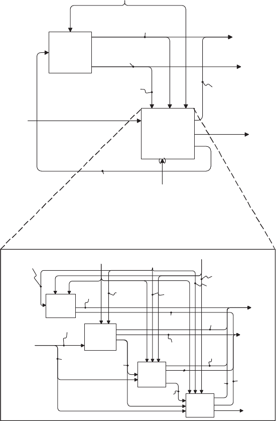
assess the impact of any uncorrectable deficiencies found in the first function,
(4) redesign the CI (component or subsystem) to address unacceptable impacts
of any uncorrectable deficiencies as identified in the third function, (5) mod ify
the baseline of the design to account for any fixes (function 2) or acceptable
impacts (requireme nts changes from function 3), and (6) integrate with the
next CI (component or subsystem) and repeat until all CIs (components or
Design
Changes
Conduct
Early
Validation
A21
Conduct
Integration &
Verification
A22
Conduct
Validation
A23
"Built-to"
Configuration
Items & Pre-
Production
Prototypes
System
Integration
Phase
Documentation
System Design
Phase
Documentation
Qualification Procedures,
Activities, & Models
Conduct
Acceptance
Testing
A24
"Built-to"
CIs
Pre-Production
Prototypes
Acceptance
Testing
Document
Validation
Document
Verification
Document
Early
Validation
Document
Early
Validation
Changes
Verification
Changes
Validation
Changes
Acceptance
Changes
Operational
Concept
Acceptance
Criteria &
Thresholds
Verification
Data
Validation
Data
Operational
System
Acceptance
or Rejection
Inputs of Stakeholders
Operational Concept,
Stakeholders’ Requirements,
Derived Requirements
Derived &
Stakeholders’
Requirements
Perform
Design
Activities
A1
Perform
Qualification
& Integration
Activities
A2
System Design
Phase
Documentation
Design
Changes
System
Integration
Phase
Documentation
"Built-to"
Configuration
Items & Pre-
Production
Prototypes
Inputs of Stakeholders
System Design &
Integration
Documentation
Qualification
System Design
Documentation
Qualification Procedures,
Activities, & Models
Qualification
System Design
Documentation
Operational
System
Qualification
System
FIGURE 11.3 Bottom-up integration process.
11.3 OVERVIEW OF INTEGRATION 347
subsystems) have been integrated. Figure 11.4 addresses component integration
but has the identical structure for the higher level integration at the subsystem
and system levels.
Figure 11.5 shows logic structure of integration at the subsystem level, that
is, integrating every subsystem of the system until all subsystems have been
Verification
Data
Perform
Component
Integration &
Verification
A221
Perform
Subsystem
Integration &
Verification
A222
Perform
System
Integration &
Verification
A223
Qualification Procedures,
Activities, & Models
"Built-to"
CIs
Verification
Changes
Verification
Document
Component Level
Design Documents
Subsystem Level
Design Documents
"Built-to"
Components
"Built-to"
Subsystems
System-Level
Reqression
Qualification
System-
Generated
Subsystem
Regression
Qualification
System-
Generated
Component
Regression
Qualification
Subsystem-
Generated
Component
Regression
Qualification
CI Test
Results
Subsystem
Test
Results
Component
Test
Results
System
Verification
Document
Subsystem
Verification
Documents
Component
Verification
Documents
Component
Verification
Changes
Subsystem
Verification
Changes
CI Verification
Changes
Derived &
Stakeholders’
Requirements
Stakeholders’
& System
Requirements
Documents
Inspect
&
Verify CI
A2211
Identify & Fix
Correctable
CI
Deficiencies
A2212
Assess
Impact of
Uncorrectable
CI
Deficiencies
A2213
Redesign
CI
A2214
Modify CI
Baseline
A2215
Integrate
with
Next CI
A2216
Discrepancy
Reports
CI
Engineering
Changes
Cleared
CI
Corrected CI
Uncorrected CI
Approval to
Continue
Integration
Unacceptable
Impact
Acceptable
Impact
Cleared CI
Deficient
CI
Redesigned CI
Qualification Procedures,
Activities, & Models
"Built-to"
Components
"Built-to"
CIs
CI Verification
Changes
CI Test
Results
Component
Verification
Documents
Component Level
Design Documents
Subsystem-
Generated
Component
Regression
Qualification
Baseline
Changes
Impact
Statement
System-
Generated
Component
Regression
Qualification
FIGURE 11.4 Major integration functions for component integration. (The same six
functions apply for subsystem and system integration.)
348
INTEGRATION AND QUALIFICATION
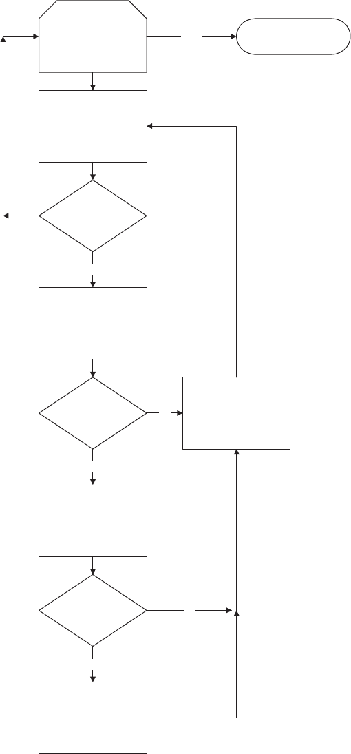
Continue until every
subsystem has been
integrated
Inspect and Test
Subystem
Deficient
Subsystem
No
Modify and Fix
Correctable
Deficiencies
Remaining
Deficiencies
No
Modify Baseline
Yes
Yes
Assess Impact of
Uncorrectable
Deficiences
No
Deficiencies
Unacceptable
Redesign Subsystem
Yes
Subsystem Integration
Complete
Yes
FIGURE 11.5 Logic diagram for subsystem integration.
349
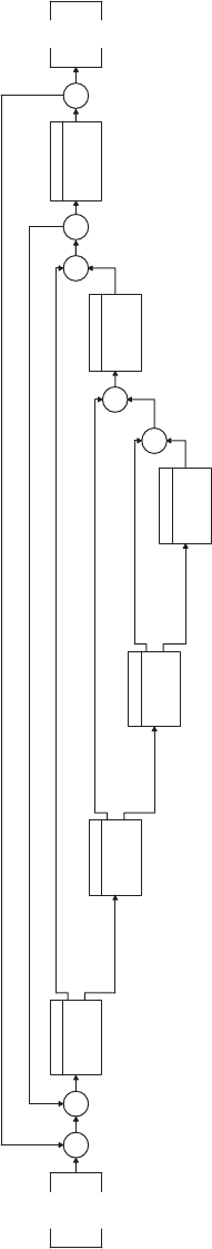
1
Perform Design
Activities
IT
IT
LP
LP
2.3.1
Inspect & Test
Subsystem
OR
2.3.2
Identify & Fix
Correctable
Deficiencies
OR
2.3.3
Assess Impact
of
Uncorrectable...
OR
2.3.4
Redesign
Subsystem
2.3.5
Modify Baseline
2.3.6
Integrate with
Next Subsystem
2.1
Perform
Component
Integration
cleared subsystem
deficient subsystem
correctable def.
uncorrectable def
acceptable impact
unacceptable impact
if deficiency is fixed or redesigned
for each subsystem
FIGURE 11.6 Integration control structure. (Subsystem integration into the System.)
350