Chiodi M. An innovative 3D-CFD-Approach towards Virtual Development of Internal Combustion Engines
Подождите немного. Документ загружается.


116 8 3D-CFD-Modeling of the Thermodynamic Properties of the Working Fluid
8.4.2.1 Heat Release at the Flame Front and Post-Oxidation of
Exhaust Gas with Fresh Gas
The local heat release
OxB
Q
,
'
at the flame front (“primary” oxidation of a discrete local amount
of fresh gas
Fresh
m'
during the combustion process) or the post-oxidation
PostOxB
Q
,,
'
of exhaust
gas
0,B
m'
with fresh gas
Fresh
m'
(“secondary” oxidation that produces a final exhaust gas with
properties “1” – see Eq. 8.55) are described in QuickSim as follows:
HRFreshfFreshfFreshOxB
hmhhmQ '' ' '
,,
(8.54)
1,0,0,0,,,, fBFreshfBFreshfFreshPostOxB
hmmhmhmQ '''' '
(8.55)
where the heat of formation of the burned gases
f
h
,
0,f
h
and
1,f
h
are calculated using Eq. 6.18
with a corresponding local fluid composition and the tabled values of the species heat of
formation (see Table 8.3 [57]). Similarly the heat of formation of the fresh gas
Freshf
h
,
becomes:
2222
,,,, NNfOOfFFfFreshf
whwhwhh
(8.56)
Table 8.3: Heat of formation
jf
h
,
of species
j
(MJ/kg).
CO H
2
O OH H O CO
2
O
2
H
2
N N
2
NO
-3.9475 -13.4339 2.31176 218 15.575 -8.94318 0 0 33.7628 0 3.00966
In QuickSim the calculation of the fuel’s heat of formation
Ff
h
,
is based on the lower heating
value
LHV
h
as input and is not strictly related to the heat of formations of the species building the
implemented fuel: C
n
H
m
O
r
N
q
. This means that the parameters n,m,r and q can be conveniently
chosen as an approximation of a more complex real composition of the fuel and the heat of
formation
Ff
h
,
can be easily calibrated to the effective
LHV
h
. From the definition of the lower
heating value
LHV
h
(heat release with complete fuel oxidation at O=1 and “frozen”
composition):
LHVFMaxOxB
hmQ ' '
,,
(8.57)
Using Eqs. 8.54 and 8.56 and the relation of a stoichiometric fuel oxidation (see Eq. 8.1) the fuel
heat of formation
Ff
h
,
becomes:
8.4 QuickSim’s Approach: Few Species for the Description of the Working Fluid 117
.
1
2
2222
,,
,
F
OHfOHCOfCOLHV
Ff
M
hM
m
hMnh
h
¸
¹
·
¨
©
§
(8.58)
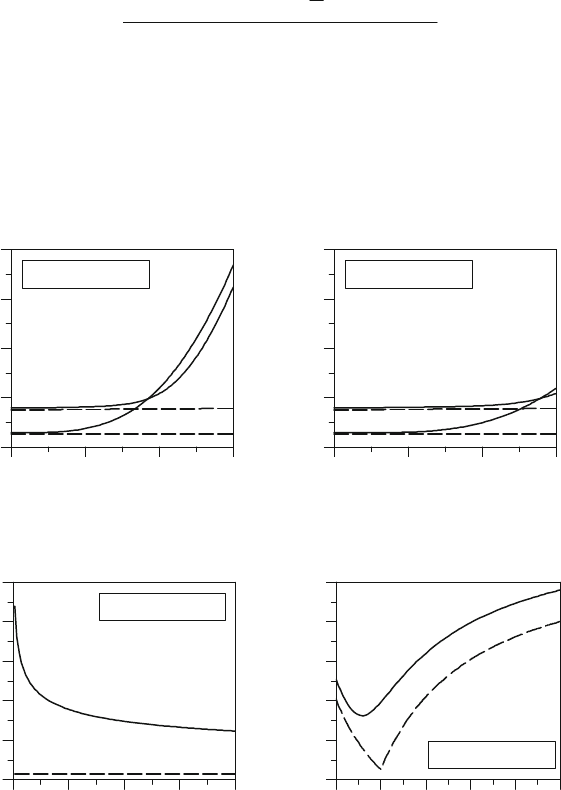
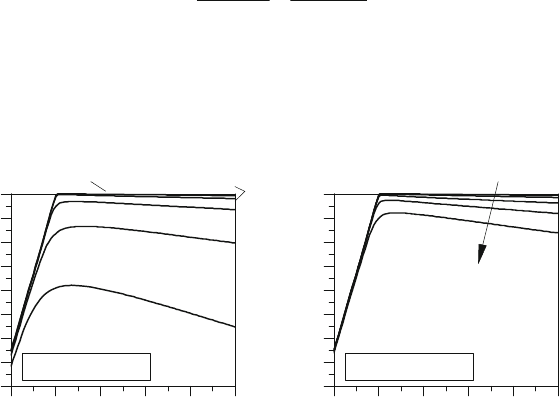
In Figures 8.14 – 8.17 the heat of formation
Ff
h
,
of the exhaust gas as a function of temperature,
pressure and lambda is reported. As expected,
Ff
h
,
rises with increasing the effect of
dissociation. This effect reduces the heat-release because a part of the energy is still stored in
species with high chemical potentials. The comparison between the assumed reaction scheme
and a simple one-step fuel-oxidation mechanism shows remarkably differences, which would
irremediably influence the heat-release evaluations.
Figure 8.14: Heat of formation
f
h
(HOF) as
function of temperature (
p
=1bar).
Figure 8.15: Heat of formation
f
h
(HOF) as
function of temperature (
p
=100bar).
Figure 8.16: Heat of formation
f
h
(HOF) as
function of pressure.
Figure 8.17: Heat of formation
f
h
(HOF) as
function of lambda.
Reaction
Scheme
1Step-Ox.
Heat of formation h
f
, MJ/kg
-3.0
-2.5
-2.0
-1.5
-1.0
Te
m
p
erature, K
1500 2000 2500 3000
C
7.9
H
14.2
O
0.12
N
0.01
p=1 bar
O=0.8
O=1.0
Reaction
Scheme
1Step-Ox.
Heat of formation h
f
, MJ/kg
-3.0
-2.5
-2.0
-1.5
-1.0
Te
m
p
erature, K
1500 2000 2500 3000
C
7.9
H
14.2
O
0.12
N
0.01
p=100 bar
O=0.8
O=1.0
Reaction
Scheme
1Step-Ox.
Heat of formation h
f
, MJ/kg
-2.9
-2.7
-2.5
-2.3
-2.1
-1.9
Pressure,
b
ar
0 25 50 75 100
C
7.9
H
14.2
O
0.12
N
0.01
T=2700 K
O=1.0
Heat of formation h
f
, MJ/kg
-3.0
-2.5
-2.0
-1.5
-1.0
-0.5
O, -
0.5 1.0 1.5 2.0 2.5 3.0
C
7.9
H
14.2
O
0.12
N
0.01
T=2700 K
p=1 bar
Reaction
Scheme
1Step-Ox.
118 8 3D-CFD-Modeling of the Thermodynamic Properties of the Working Fluid
8.4.2.2 Heat Exchange due to Dissociation Effects and Post-Oxidation
within Exhaust Gas
According to Eq. 8.53 the heat exchange in the burned zone occurs when, due to temperature,
pressure and lambda changes, chemical reactions take place. These changes of the chemical
composition of the exhaust gas are caused by the fluid’s compression and expansion during the
working cycle, mixing processes between zones with different air/fuel ratio, etc. Similarly to the
procedure in Chapter 8.4.2.1 the variations of the heat of formation
f
h
(in particular the
gradients:
dTdh
f
,
dpdh
f
and
Oddh
f
) within the burned zone are used for a local
description of the heat-exchange amount.
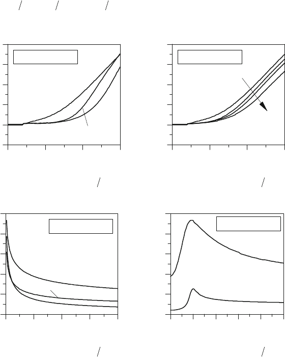
Figure 8.18: Gradient of HOF:
dTdh
f
as
function of temperature (
p
=1bar - O rich).
Figure 8.19: Gradient of HOF:
dTdh
f
as
function of temperature (
p
=1bar - O lean).
Figure 8.20: Gradient of HOF:
dTdh
f
as
function of pressure (
T
=2700K).
Figure 8.21: Gradient of HOF:
dTdh
f
as
function of lambda (
T
=2700K).
dh
f
/dT, J/kgK
-1000
0
1000
2000
3000
4000
Te
m
p
erature, K
1500 2000 2500 3000
C
7.9
H
14.2
O
0.12
N
0.01
p=1 bar
O=0.6
O=1.0
O=0.8
dh
f
/dT, J/kgK
-1000
0
1000
2000
3000
4000
Te
m
p
erature, K
1500 2000 2500 3000
C
7.9
H
14.2
O
0.12
N
0.01
p=1 bar
O=1.0
O
O=2.0
dh
f
/dT, J/kgK
0
500
1000
1500
2000
2500
Pressure,
b
ar
0 25 50 75 100
C
7.9
H
14.2
O
0.12
N
0.01
T=2700 K
O=2.0
O=1.0
O=0.8
dh
f
/dT, J/kgK
0
500
1000
1500
2000
2500
O, -
0.5 1.0 1.5 2.0 2.5 3.0
C
7.9
H
14.2
O
0.12
N
0.01
T=2700 K
p=100 bar
p=1 bar
8.4 QuickSim’s Approach: Few Species for the Description of the Working Fluid 119
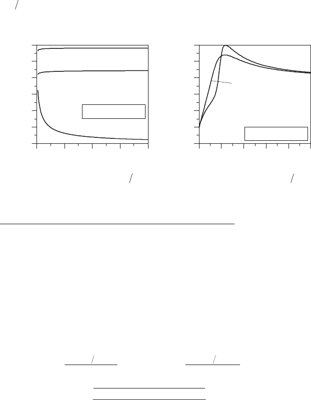
Figure 8.22: Gradient of HOF:
dpdh
f
as
function of temperature (
p
=1bar).
Figure 8.23: Gradient of HOF:
dpdh
f
as
function of pressure (
T =2700K).
Figure 8.24: Gradient of HOF:
dpdh
f
as
function of lambda (
T
=2700K).
Figure 8.25: Gradient of HOF:
Oddh
f
as
function of temperature (
p
=1bar).
In Figures 8.18 – 8.27 the gradients of the heat of formation of the burned gas are reported. A
positive gradient means the trend of the exhaust gas to convert thermal energy (
h ) into chemical
energy. At low temperatures where the composition is frozen, the gradients
dTdh
f
and
dpdh
f
are zero. These gradients rise exponentially with increasing the temperature and the
influence is more decisive when
#O
1 and the pressure is low. In particular the pressure hinders
dissociation effects at any lambda value, i.e. the contribution of the gradients
dTdh
f
and
dpdh
f
to the heat-exchange drastically decreases as soon as the pressure rises. The contribute
of
Oddh
f
(mixing processes) to the heat-exchange is of higher complexity. The oxidation of a
“rich” burned gas is accompanied by heat release as long as the temperature is not so high that
dh
f
/dp, J/kg/Pa
-5
-4
-3
-2
-1
0
Te
m
p
erature, K
1500 2000 2500 3000
C
7.9
H
14.2
O
0.12
N
0.01
p=1 bar
O=2.0
O=1.0
O=0.8
dh
f
/dp, J/kg/Pa
-2.5
-2
-1.5
-1
-0.5
0
Pressure,
b
ar
0 25 50 75 100
C
7.9
H
14.2
O
0.12
N
0.01
O=2.0
O=1.0
O=0.8
T=2700 K
dh
f
/dp, J/kg/Pa
-2.5
-2
-1.5
-1
-0.5
0
0.5
O, -
0.5 1.0 1.5 2.0 2.5 3.0
C
7.9
H
14.2
O
0.12
N
0.01
T=2700 K
p=100 bar
p=1 bar
dh
f
/dO, MJ/kg/-
-1.5
-1.0
-0.5
0.0
0.5
1.0
1.5
Te
m
p
erature, K
1500 2000 2500 3000
C
7.9
H
14.2
O
0.12
N
0.01
p=1 bar
O=2.0
O=1.0
O=0.8
120 8 3D-CFD-Modeling of the Thermodynamic Properties of the Working Fluid
dissociation “absorbs” energy (see Figure 8.25). An increasing pressure has low influence on
Oddh
f
for “lean” burned gases but helps the post-oxidation of a “rich” burned gas because
dissociation effects slow down.
Figure 8.26: Gradient of HOF:
Oddh
f
as
function of pressure (
T
=2700K).
Figure 8.27: Gradient of HOF:
Oddh
f
as
function of lambda (
T
=2700K).
Mixing Process of Exhaust Gases with and without Heat Exchange
The separation of the thermal and chemical enthalpy to different 3D-CFD-models (see
Figure 8.3) for the calculation of the thermodynamic properties of the working fluid and the heat
release (combustion at the flame front, post-oxidation and dissociation) allows a selective
activation of these models depending on the thermodynamic conditions at which the processes
take place. E.g., during the expansion or exhaust stroke a local mixing process at
low temperature (
T <1000 K) between two zones of burned gases (
1,B
m'
and
2,B
m'
)
with different temperatures and compositions (
1,_ BAir
w
,
1,_ BF
w
,
2,_ BAir
w
and
2,_ BF
w
)
leads numerically, due to the conservation equations, to a final exhaust gas
3,B
m'
, that, among
other things, has the resulting composition:
''
''
O
O O
Min
BBFBBF
BBAirBBAir
B
BFBAir
B
BFBAir
B
L
mwmw
mwmw
L
ww
L
ww
2,2,_1,1,_
2,2,_1,1,_
3,
min
2,_2,_
2,
min
1,_1,_
1,
&
(8.59)
The error caused by assuming this final composition as a new chemical equilibrium instead of
the sum of two frozen compositions affects moderately the thermal properties of the burned gas
dh
f
/dO, MJ/kg/-
-1.5
-1.0
-0.5
0.0
0.5
1.0
1.5
Pressure,
b
ar
0 25 50 75 100
C
7.9
H
14.2
O
0.12
N
0.01
O=2.0
O=1.0
O=0.8
T=2700 K
dh
f
/dO, MJ/kg/-
-4.0
-3.0
-2.0
-1.0
0.0
1.0
2.0
O, -
0.5 1.0 1.5 2.0 2.5 3.0
C
7.9
H
14.2
O
0.12
N
0.01
T=2700 K
p=100 bar
p=1 bar
8.4 QuickSim’s Approach: Few Species for the Description of the Working Fluid 121
but it would be inacceptable if this mixing process generates a heat source, what would be
definitely unrealistic. For this reason the code can decide whether a process, due to numerical
chemical reactions, is plausibly related to heat-exchange or not.
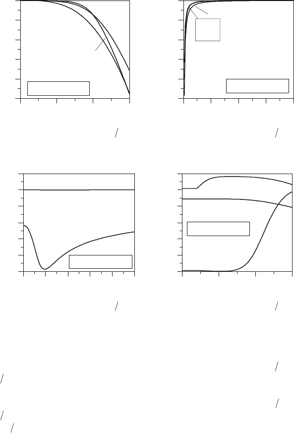
8.4.2.3 Combustion Conversion Efficiency
According to Eqs. 8.54 and 8.57 a local combustion conversion efficiency
HR
K can be
introduced [12,34]:
.
,
,,
,
LHVF
OxB
MaxOxB
OxB
HR
hm
Q
Q
Q
'
'
'
'
K
(8.60)
This efficiency describes the ratio of the oxidation heat release of a given local mixture at a final
combustion temperature
T
to the maximal heat release for a full fuel oxidation, i.e. starting from
a local fuel mass
F
m'
the efficiency due to incomplete combustion or incomplete oxidation can
be calculated (see Figures 8.28 and 8.29).
Figure 8.28: Combustion conversion
efficiency
HR
K
(
p
=1 bar).
Figure 8.29: Combustion conversion
efficiency
HR
K
(
p
=100 bar).
For rich mixtures these figures show a remarkable effective reduction of
HR
K
that can be clearly
explained with oxygen deficit. At low temperatures
T
(frozen state) for tO 1, a full oxidation is
possible so that theoretically
K
HR
1 (an imperfect combustion is not taken into account - see
4.4.3). At higher temperatures dissociation effects reduce the heat release, because a part of the
chemical energy remains stored in molecules with high chemical potential. This is a fictive
reduction of
HR
K
, because as soon as temperature drops the stored “dissociation-energy” can be
p=1 bar
Comb. co
n
v
. efficie
n
c
y
K
HR
, %
20
30
40
50
60
70
80
90
100
O, -
0.5 1.0 1.5 2.0 2.5 3.0
C
7.9
H
14.2
O
0.12
N
0.01
T=2800 K
T=2500 K
T=2200 K
T=1600 K
T=1900 K
Comb. co
n
v
. efficie
n
c
y
K
HR
, %
20
30
40
50
60
70
80
90
100
O, -
0.5 1.0 1.5 2.0 2.5 3.0
C
7.9
H
14.2
O
0.12
N
0.01
T=2800 K
T=1600 K
p=100 bar
T
122 8 3D-CFD-Modeling of the Thermodynamic Properties of the Working Fluid
released. That means that during the working cycle in IC-engines dissociation acts as an energy
“capacitor”, that is, depending of temperature and pressure, more or less charged during
combustion and discharged during the expansion stroke.
9
3D-CFD-Modeling of the
Combustion for SI-Engines
In the previous chapter it has been explained that 3D-CFD combustion models are usually heat-
release models. These models first calculate the local burn rate and consequently using the
thermo-chemical properties of the working fluid the related local heat-release.
Heat-release models in QuickSim have been developed for both spark-ignition (based on a burn
rate calculation as a function of the flame front propagation within a turbulent partially-premixed
mixture) and compression ignition engines (based on both self-ignition mechanisms and
diffusive flame propagations). In this chapter the approach in the modeling of the flame
propagation within the combustion chamber during the combustion of SI-engines is presented.
9.1 Introduction
Starting from an initial flame kernel generated during the ignition process at the spark plug, the
flame propagates up to a certain radius under laminar conditions, then the flame reaches a
characteristic dimension at which the interactions with the turbulent eddies support the local
oxidation process and the flame speed remarkably increases (more details in [5,55,58,59,61]).
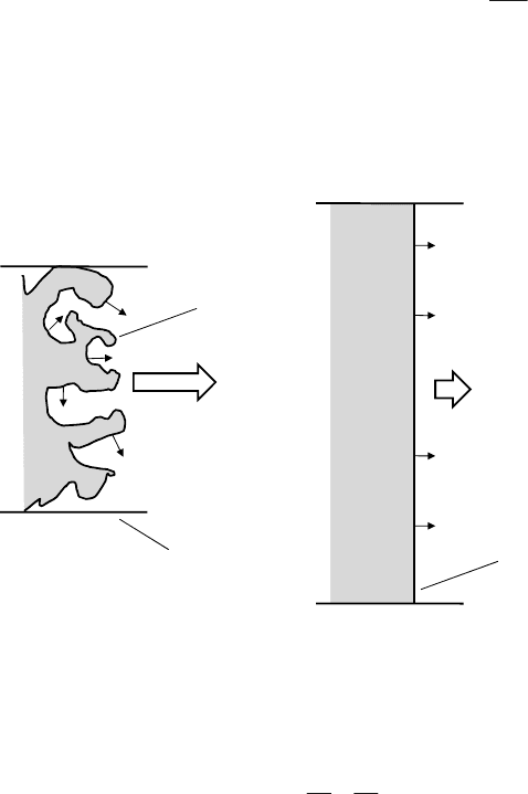
Following the schematic of a turbulent flame propagation in a duct with a section area
Tf
A
,
(see
Figure 9.1) the flame can be modeled as a thin oxidation-sheet wrinkled by turbulent eddies
where the behavior of a laminar flame structure remains locally unchanged (flamelet approach).
The increasing of the flame speed
T
S under turbulent conditions is then explained with the
increasing of the effective surface of the wrinkled flame
TfLf
AA
,,
!
(ensemble of local laminar
flames with different flow conditions like: stretch, wrinkling, velocities, etc.). Based on this
approach the burn rate rises due to the increasing of the oxidation region.
M. Chiodi, An Innovative 3D-CFD-Approach towards Virtual Development of
Internal Combustion Engines, DOI 10.1007/978-3-8348-8131-1_9,
© Vieweg+Teubner Verlag | Springer Fachmedien Wiesbaden GmbH 2011
124 9 3D-CFD-Modeling of the Combustion for SI-Engines
Following the mass balance the relation between the laminar
L
S
and the turbulent flame speed
T
S
can be defined as follows:
Tf
Lf
LTLfLUTfTU
A
A
SSASAS
,
,
,,
U U
(9.1)
where the laminar flame speed
),,,(
,_,, jUEGRjUjjFreshL
xTpS O
in a cell
j
of the 3D-CFD-
mesh is formulated, e.g. with the relations reported in Chapter 4.4.3.2. Figures 9.2, 9.3 and 9.4
show the profiles of
L
S
as function of lambda, pressure and temperature for a commercial
gasoline fuel. As well known the maximal laminar flame speed
L
S
is reached with a rich mixture
at
#O
Fresh
0.9.
Figure 9.1: Schematic of turbulent flame propagation
(flamelet approach of a wrinkled flame).
Several models for the description of the wrinkling factor
K
have been proposed. Despite a lot
controversy most of these models recognize the following trend:
LL
T
S
u
S
S
K
c
~
(9.2)
i.e. the turbulence intensity
u
c
is the most sensitive variable for the calculation of the wrinkling
factor
K
and consequentially the turbulent flame speed
T
S
. Based on this modeling the
turbulent flame speed
T
S
rises with increasing the turbulence intensity
u
c
(see Figure 9.5). In
Flame Front
Speed =
L
S
L
S
L
S
L
S
L
S
L
S
L
S
L
S
L
S
L
S
Flame Front
Speed =
T
S
Flame
Surface =
Lf
A
,
Duct cross
section=
Tf
A
,
Equivalent duct
cross section=
Lf
A
,
9.1 Introduction 125
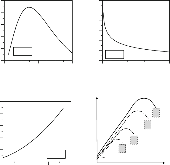
reality it has to be noticed that a continued increasing of
u
c
increases
T
S
up to a maximum
followed by a reduction and, at the end, a flame extinction. An explanation of this behavior can
be found considering the local flame strain caused by the turbulence. The Turbulence is
responsible for an increasing convection, i.e. among other things, the supply of reactants towards
the flame positively increases [55]. On the other hand high convection rates lead to steeper
gradients of the flame surface that increase local diffusive losses. When the finite rate of the
chemical kinetics is unable to generate products as fast as reactants are delivered and products,
including enthalpy are removed by diffusion, the local flame temperature and consequently the
reaction rate remarkably decrease. If the flame temperature is too low the whole combustion
process becomes unstable and locally the flame suddenly extinguishes.
Figure 9.2: Laminar flame speed
L
S as
function of lambda (fuel: gasoline).
Figure 9.3: Laminar flame speed
L
S as
function of pressure (fuel: gasoline).
Figure 9.4: Laminar flame speed
L
S
as
function of temperature (fuel: gasoline).
Figure 9.5: Dependence of turbulent flame
speed
T
S
on the turbulence intensity.
Laminar flame speed S
L
, m/s
1.0
1.5
2.0
2.5
3.0
3.5
O, -
0.6 0.8 1.0 1.2 1.4
gasoline
T=900 K
p=1 bar
Laminar flame speed S
L
, m/s
1.0
1.5
2.0
2.5
3.0
3.5
4.0
Pressure,
b
ar
0 10 20 30 40
gasoline
T=900 K
O=1
Laminar flame speed S
L
, m/s
0.0
1.0
2.0
3.0
4.0
5.0
Te
m
p
erature, K
300 600 900 1200
gasoline
p=1 bar
O=1
T
S
L
S
u
c
9.0 O
1.1 O
2.1 O
3.1 O