Fitzgerald A.E. Electric Machinery
Подождите немного. Документ загружается.

176 CHAPTER 4 Introduction to Rotating Machines
nonuniformity of air-gap reluctance associated with variations in rotor position in
conjunction with time-varying currents applied to their stator windings. In such ma-
chines, both the stator and rotor structures are subjected to time-varying magnetic
flux and, as a result, both may require lamination to reduce eddy-current losses.
Rotating electric machines take many forms and are known by many names: dc,
synchronous, permanent-magnet, induction, variable reluctance, hysteresis, brush-
less, and so on. Although these machines appear to be quite dissimilar, the physical
principles governing their behavior are quite similar, and it is often helpful to think
of them in terms of the same physical picture. For example, analysis of a dc machine
shows that associated with both the rotor and the stator are magnetic flux distributions
which are fixed in space and that the torque-producing characteristic of the dc machine
stems from the tendency of these flux distributions to align. An induction machine, in
spite of many fundamental differences, works on exactly the same principle; one can
identify flux distributions associated with the rotor and stator. Although they are not
stationary but rather rotate in synchronism, just as in a dc motor they are displaced by
a constant angular separation, and torque is produced by the tendency of these flux
distribution to align.
Certainly, analytically based models are essential to the analysis and design of
electric machines, and such models will be derived thoughout this book. However,
it is also important to recognize that physical insight into the performance of these
devices is equally useful. One objective of this and subsequent chapters is to guide
the reader in the development of such insight.
4,2
INTRODUCTION TO AC AND DC
MACHINES
4.2.1 AC Machines
Traditional ac machines fall into one of two categories:
synchronous
and
induction.
In synchronous machines, rotor-winding currents are supplied directly from the sta-
tionary frame through a rotating contact. In induction machines, rotor currents are
induced in the rotor windings by a combination of the time-variation of the stator
currents and the motion of the rotor relative to the stator.
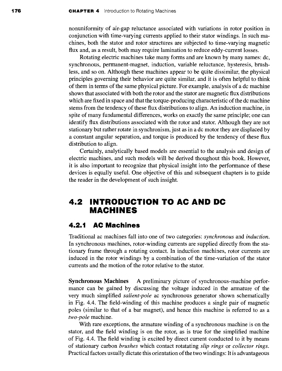
Synchronous Machines A preliminary picture of synchronous-machine perfor-
mance can be gained by discussing the voltage induced in the armature of the
very much simplified
salient-pole
ac synchronous generator shown schematically
in Fig. 4.4. The field-winding of this machine produces a single pair of magnetic
poles (similar to that of a bar magnet), and hence this machine is referred to as a
two-pole
machine.
With rare exceptions, the armature winding of a synchronous machine is on the
stator, and the field winding is on the rotor, as is true for the simplified machine
of Fig. 4.4. The field winding is excited by direct current conducted to it by means
of stationary carbon
brushes
which contact rotatating
slip rings
or
collector rings.
Practical factors usually dictate this orientation of the two windings: It is advantageous
4.2 Introduction to AC and DC Machines 177
~ld
nding
Flux
paths
Figure
4.4 Schematic view of a simple,
two-pole, single-phase synchronous
generator.
to have the single, low-power field winding on the rotor while having the high-power,
typically multiple-phase, armature winding on the stator.
The armature winding, consisting here of only a single coil of N turns, is indicated
in cross section by the two coil sides a and -a placed in diametrically opposite narrow
slots on the inner periphery of the stator of Fig. 4.4. The conductors forming these
coil sides are parallel to the shaft of the machine and are connected in series by
end connections (not shown in the figure). The rotor is turned at a constant speed
by a source of mechanical power connected to its shaft. The armature winding is
assumed to be open-circuited and hence the flux in this machine is produced by the
field winding alone. Flux paths are shown schematically by dashed lines in Fig. 4.4.
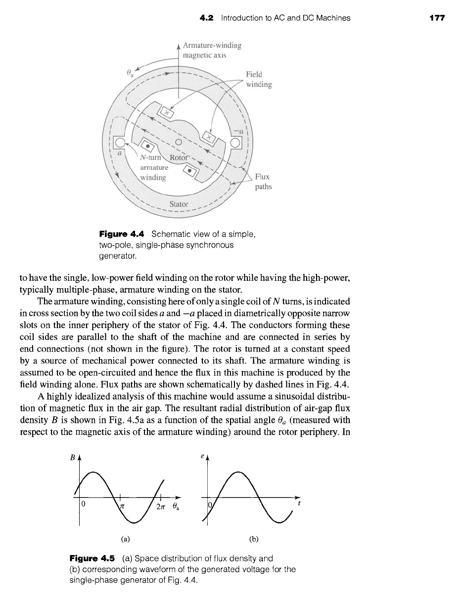
A highly idealized analysis of this machine would assume a sinusoidal distribu-
tion of magnetic flux in the air gap. The resultant radial distribution of air-gap flux
density B is shown in Fig. 4.5a as a function of the spatial angle
Oa
(measured with
respect to the magnetic axis of the armature winding) around the rotor periphery. In
I ° o:
e
~t
(a) (b)
Figure
4.5 (a) Space distribution of flux density and
(b) corresponding waveform of the generated voltage for the
single-phase generator of Fig. 4.4.
178 CHAPTER 4 Introduction to Rotating Machines
practice, the air-gap flux-density of practical salient-pole machines can be made to
approximate a sinusoidal distribution by properly shaping the pole faces.
As the rotor rotates, the flux-linkages of the armature winding change with time.
Under the assumption of a sinusoidal flux distribution and constant rotor speed, the
resulting coil voltage will be sinusoidal in time as shown in Fig. 4.5b. The coil
voltage passes through a complete cycle for each revolution of the two-pole machine
of Fig. 4.4. Its frequency in cycles per second (Hz) is the same as the speed of the
rotor in revolutions per second: the electric frequency of the generated voltage is
synchronized with the mechanical speed, and this is the reason for the designation
"synchronous" machine. Thus a two-pole synchronous machine must revolve at 3600
revolutions per minute to produce a 60-Hz voltage.
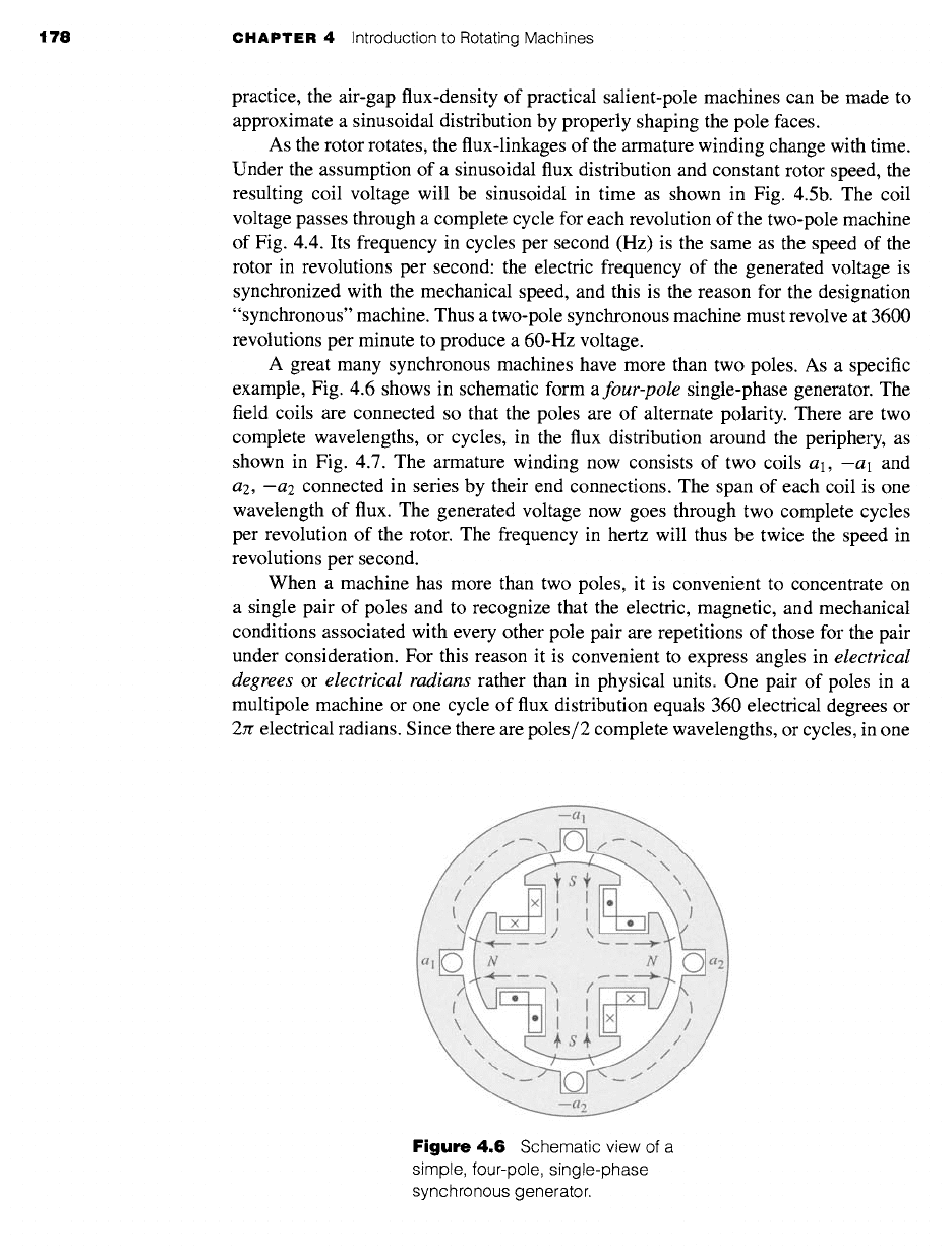
A great many synchronous machines have more than two poles. As a specific
example, Fig. 4.6 shows in schematic form a
four-pole single-phase generator. The
field coils are connected so that the poles are of alternate polarity. There are two
complete wavelengths, or cycles, in the flux distribution around the periphery, as
shown in Fig. 4.7. The armature winding now consists of two coils al, -al and
a2, --a2
connected in series by their end connections. The span of each coil is one
wavelength of flux. The generated voltage now goes through two complete cycles
per revolution of the rotor. The frequency in hertz will thus be twice the speed in
revolutions per second.
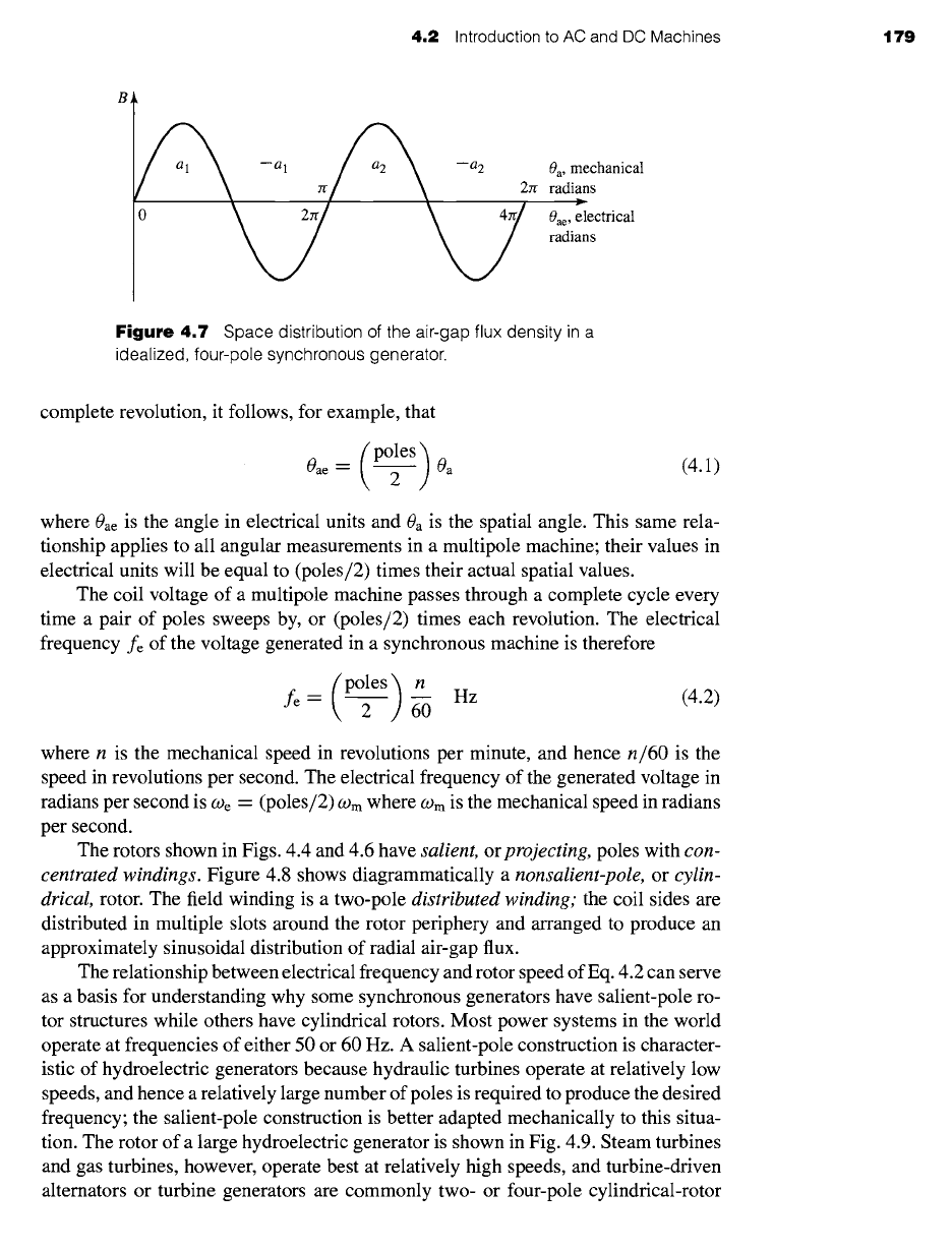
When a machine has more than two poles, it is convenient to concentrate on
a single pair of poles and to recognize that the electric, magnetic, and mechanical
conditions associated with every other pole pair are repetitions of those for the pair
under consideration. For this reason it is convenient to express angles in
electrical
degrees
or electrical radians rather than in physical units. One pair of poles in a
multipole machine or one cycle of flux distribution equals 360 electrical degrees or
2Jr electrical radians. Since there are poles/2 complete wavelengths, or cycles, in one
Figure 4.6
Schematic view of a
simple, four-pole, single-phase
synchronous generator.
4.2
Introduction to AC and DC Machines 179
--al ~ --a2 0a, mechanical
' \ zr// \ 2zr radians
0 Oae, electrical
radians
Figure
4.7 Space distribution of the air-gap flux density in a
idealized, four-pole synchronous generator.
complete revolution, it follows, for example, that
(p°les) Oa (4.1)
0ae =
2
where 0ae is the angle in electrical units and 0a is the spatial angle. This same rela-
tionship applies to all angular measurements in a multipole machine; their values in
electrical units will be equal to (poles/2) times their actual spatial values.
The coil voltage of a multipole machine passes through a complete cycle every
time a pair of poles sweeps by, or (poles/2) times each revolution. The electrical
frequency fe of the voltage generated in a synchronous machine is therefore
fe -- (ples) n
Hz (4.2)
where n is the mechanical speed in revolutions per minute, and hence
n/60
is the
speed in revolutions per second. The electrical frequency of the generated voltage in
radians per second is We = (poles/2) corn where corn is the mechanical speed in radians
per second.
The rotors shown in Figs. 4.4 and 4.6 have
salient,
or
projecting,
poles with
con-
centrated windings.
Figure 4.8 shows diagrammatically a
nonsalient-pole,
or
cylin-
drical
rotor. The field winding is a two-pole
distributed winding;
the coil sides are
distributed in multiple slots around the rotor periphery and arranged to produce an
approximately sinusoidal distribution of radial air-gap flux.
The relationship between electrical frequency and rotor speed of Eq. 4.2 can serve
as a basis for understanding why some synchronous generators have salient-pole ro-
tor structures while others have cylindrical rotors. Most power systems in the world
operate at frequencies of either 50 or 60 Hz. A salient-pole construction is character-
istic of hydroelectric generators because hydraulic turbines operate at relatively low
speeds, and hence a relatively large number of poles is required to produce the desired
frequency; the salient-pole construction is better adapted mechanically to this situa-
tion. The rotor of a large hydroelectric generator is shown in Fig. 4.9. Steam turbines
and gas turbines, however, operate best at relatively high speeds, and turbine-driven
alternators or turbine generators are commonly two- or four-pole cylindrical-rotor
180 CHAPTER 4 Introduction to Rotating Machines
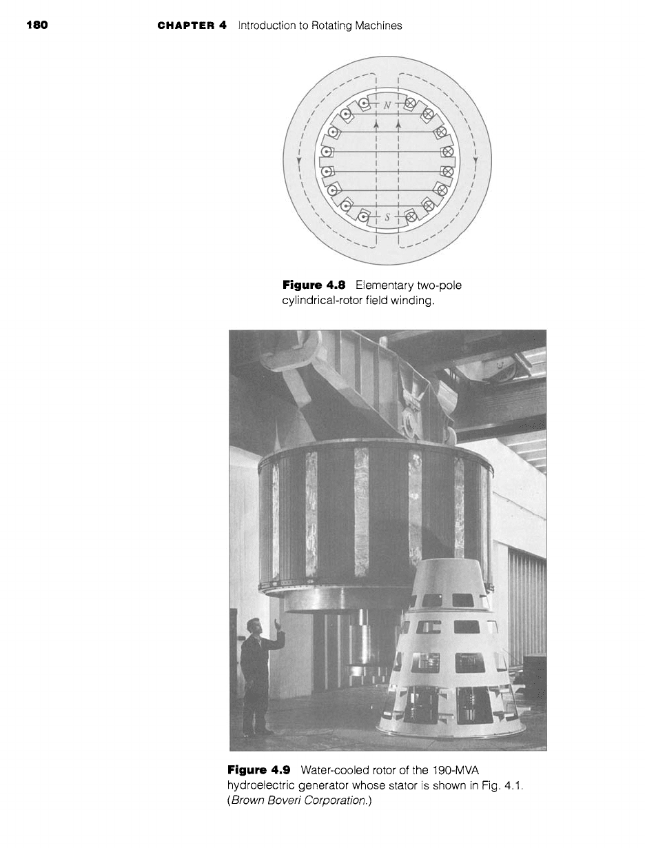
Figure
4.8 Elementary two-pole
cylindrical-rotor field winding.
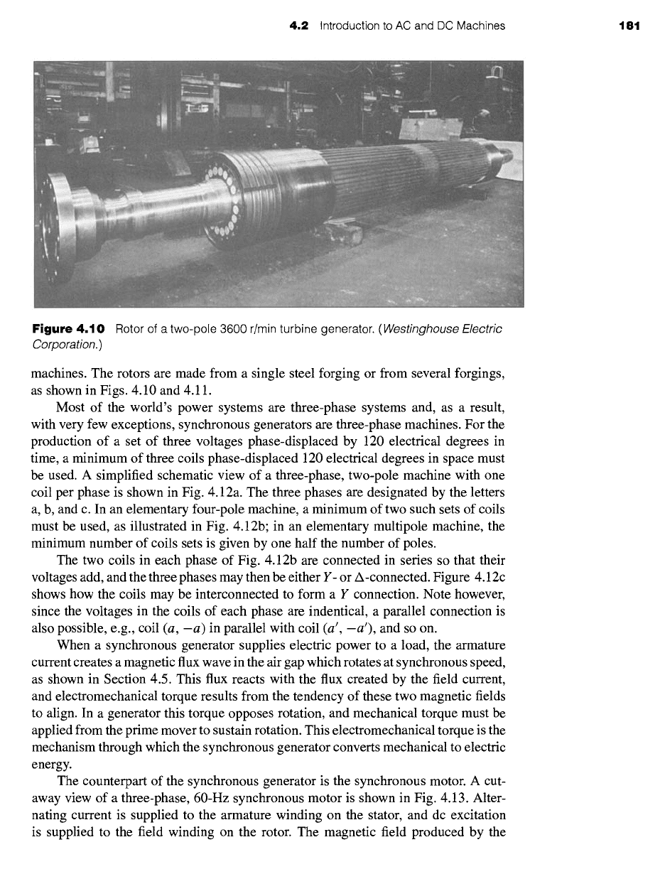
Figure 4.9
Water-cooled rotor of the 190-MVA
hydroelectric generator whose stator is shown in Fig. 4.1.
(Brown Boveri Corporation.)
4.2
Introduction to AC and DC Machines t81
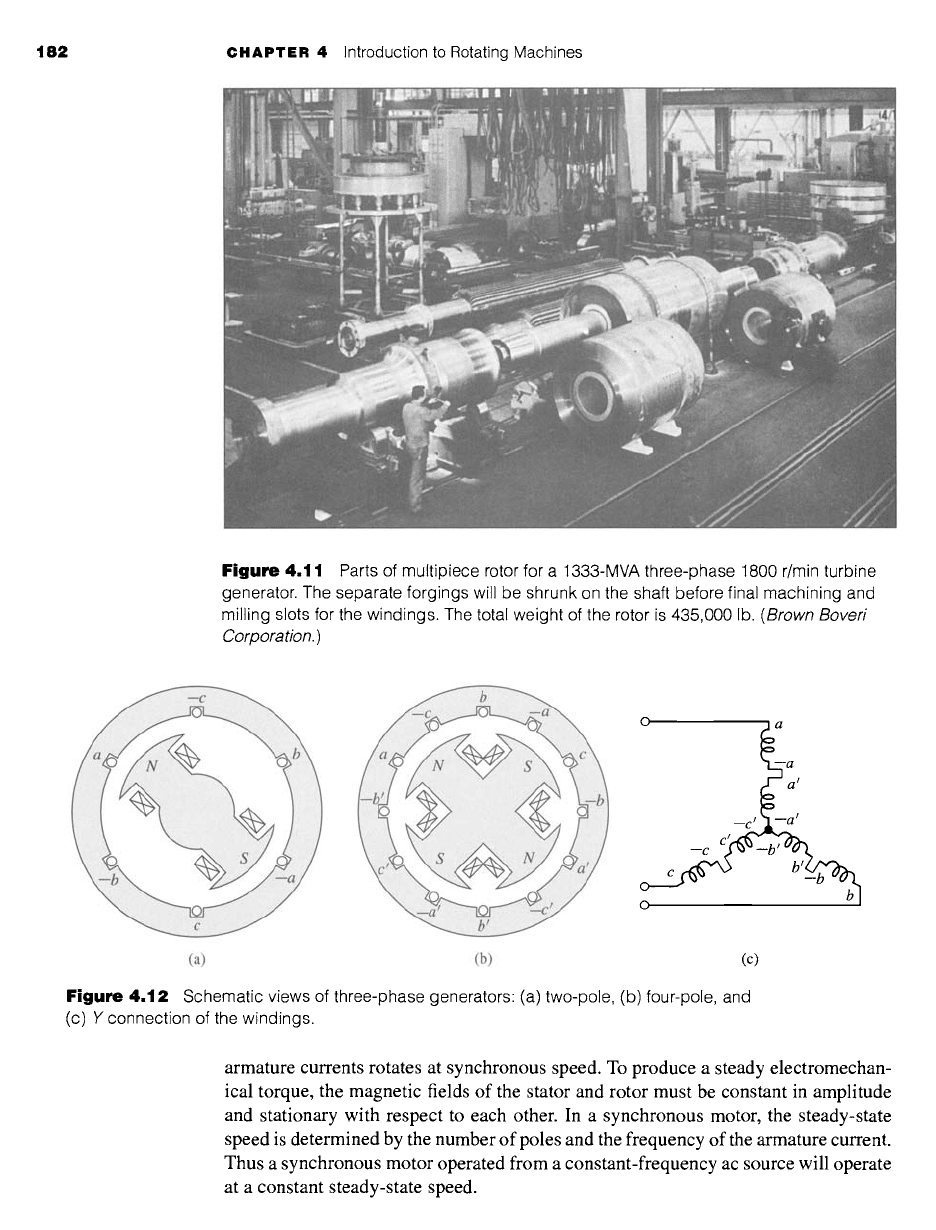
Figure
4.10 Rotor of a two-pole 3600 r/min turbine generator.
(Westinghouse Electric
Corporation.)
machines. The rotors are made from a single steel forging or from several forgings,
as shown in Figs. 4.10 and 4.11.
Most of the world's power systems are three-phase systems and, as a result,
with very few exceptions, synchronous generators are three-phase machines. For the
production of a set of three voltages phase-displaced by 120 electrical degrees in
time, a minimum of three coils phase-displaced 120 electrical degrees in space must
be used. A simplified schematic view of a three-phase, two-pole machine with one
coil per phase is shown in Fig. 4.12a. The three phases are designated by the letters
a, b, and c. In an elementary four-pole machine, a minimum of two such sets of coils
must be used, as illustrated in Fig. 4.12b; in an elementary multipole machine, the
minimum number of coils sets is given by one half the number of poles.
The two coils in each phase of Fig. 4.12b are connected in series so that their
voltages add, and the three phases may then be either Y- or A-connected. Figure 4.12c
shows how the coils may be interconnected to form a Y connection. Note however,
since the voltages in the coils of each phase are indentical, a parallel connection is
also possible, e.g., coil (a, -a) in parallel with coil (a', -a'), and so on.
When a synchronous generator supplies electric power to a load, the armature
current creates a magnetic flux wave in the air gap which rotates at synchronous speed,
as shown in Section 4.5. This flux reacts with the flux created by the field current,
and electromechanical torque results from the tendency of these two magnetic fields
to align. In a generator this torque opposes rotation, and mechanical torque must be
applied from the prime mover to sustain rotation. This electromechanical torque is the
mechanism through which the synchronous generator converts mechanical to electric
energy.
The counterpart of the synchronous generator is the synchronous motor. A cut-
away view of a three-phase, 60-Hz synchronous motor is shown in Fig. 4.13. Alter-
nating current is supplied to the armature winding on the stator, and dc excitation
is supplied to the field winding on the rotor. The magnetic field produced by the
182 CHAPTER 4 Introduction to Rotating Machines
Figure
4.11 Parts of multipiece rotor for a 1333-MVA three-phase 1800 r/min turbine
generator. The separate forgings will be shrunk on the shaft before final machining and
milling slots for the windings. The total weight of the rotor is 435,000 lb.
(Brown Boveri
Corporation.)
o a a
a l
0
(a) (b) (c)
Figure
4.12 Schematic views of three-phase generators: (a) two-pole, (b) four-pole, and
(c) Y connection of the windings.
armature currents rotates at synchronous speed. To produce a steady electromechan-
ical torque, the magnetic fields of the stator and rotor must be constant in amplitude
and stationary with respect to each other. In a synchronous motor, the steady-state
speed is determined by the number of poles and the frequency of the armature current.
Thus a synchronous motor operated from a constant-frequency ac source will operate
at a constant steady-state speed.
4.2 Introduction to AC and DC Machines 183
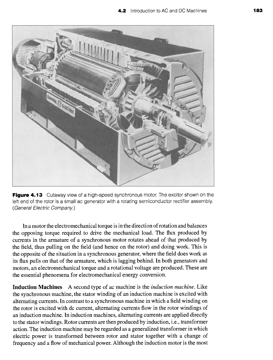
Figure
4.13 Cutaway view of a high-speed synchronous motor. The excitor shown on the
left end of the rotor is a small ac generator with a rotating semiconductor rectifier assembly.
(General Electric Company.)
In a motor the electromechanical torque is in the direction of rotation and balances
the opposing torque required to drive the mechanical load. The flux produced by
currents in the armature of a synchronous motor rotates ahead of that produced by
the field, thus pulling on the field (and hence on the rotor) and doing work. This is
the opposite of the situation in a synchronous generator, where the field does work as
its flux pulls on that of the armature, which is lagging behind. In both generators and
motors, an electromechanical torque and a rotational voltage are produced. These are
the essential phenomena for electromechanical energy conversion.
Induction Machines
A second type of ac machine is the
induction machine.
Like
the synchronous machine, the stator winding of an induction machine is excited with
alternating currents. In contrast to a synchronous machine in which a field winding on
the rotor is excited with dc current, alternating currents flow in the rotor windings of
an induction machine. In induction machines, alternating currents are applied directly
to the stator windings. Rotor currents are then produced by induction, i.e., transformer
action. The induction machine may be regarded as a generalized transformer in which
electric power is transformed between rotor and stator together with a change of
frequency and a flow of mechanical power. Although the induction motor is the most
184 CHAPTER 4 Introduction to Rotating Machines
common of all motors, it is seldom used as a generator; its performance characteristics
as a generator are unsatisfactory for most applications, although in recent years it has
been found to be well suited for wind-power applications. The induction machine
may also be used as a frequency changer.
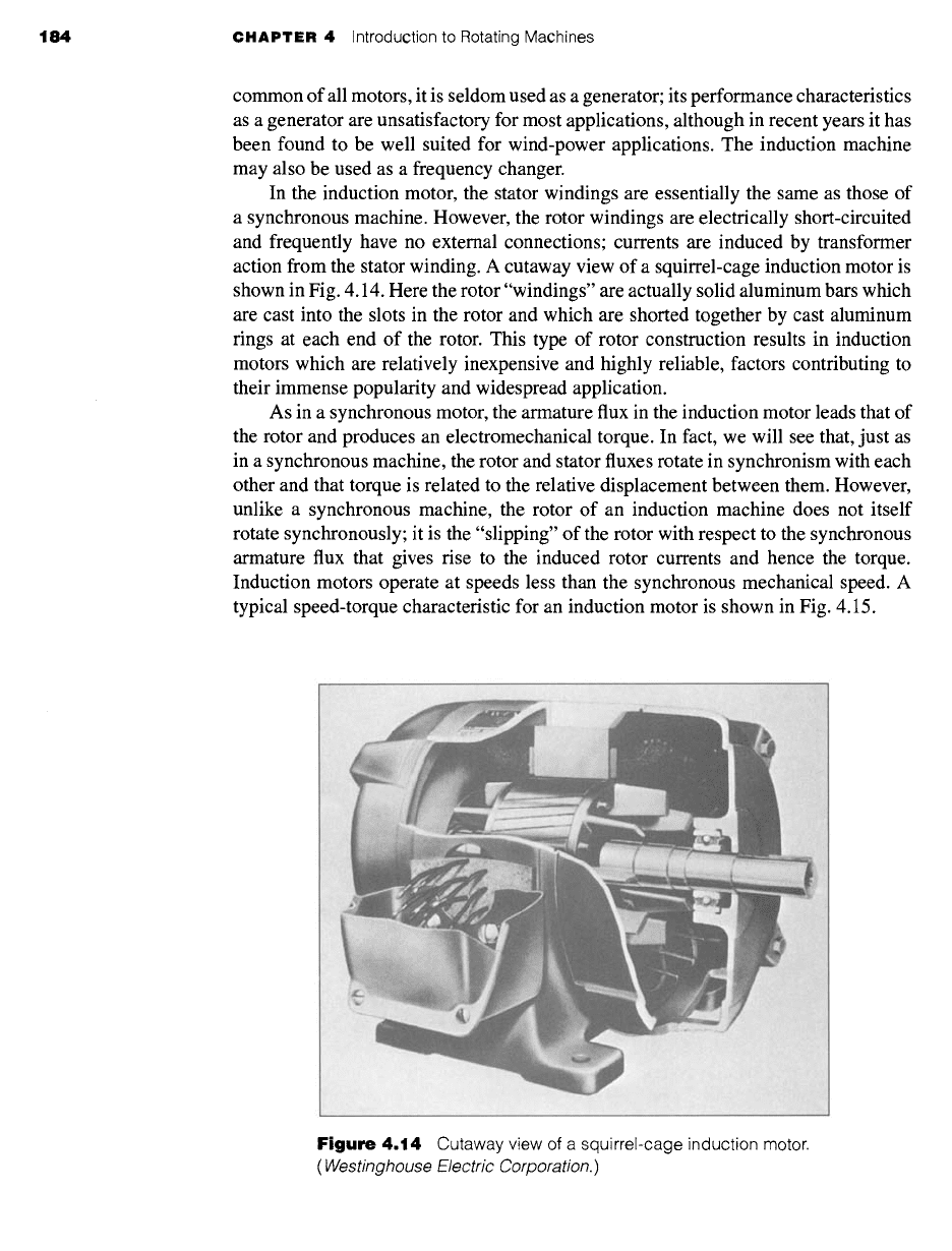
In the induction motor, the stator windings are essentially the same as those of
a synchronous machine. However, the rotor windings are electrically short-circuited
and frequently have no external connections; currents are induced by transformer
action from the stator winding. A cutaway view of a squirrel-cage induction motor is
shown in Fig. 4.14. Here the rotor "windings" are actually solid aluminum bars which
are cast into the slots in the rotor and which are shorted together by cast aluminum
rings at each end of the rotor. This type of rotor construction results in induction
motors which are relatively inexpensive and highly reliable, factors contributing to
their immense popularity and widespread application.
As in a synchronous motor, the armature flux in the induction motor leads that of
the rotor and produces an electromechanical torque. In fact, we will see that, just as
in a synchronous machine, the rotor and stator fluxes rotate in synchronism with each
other and that torque is related to the relative displacement between them. However,
unlike a synchronous machine, the rotor of an induction machine does not itself
rotate synchronously; it is the "slipping" of the rotor with respect to the synchronous
armature flux that gives rise to the induced rotor currents and hence the torque.
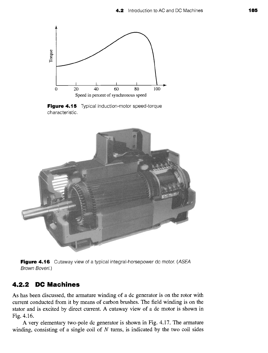
Induction motors operate at speeds less than the synchronous mechanical speed. A
typical speed-torque characteristic for an induction motor is shown in Fig. 4.15.
Figure
4.14 Cutaway view of a squirrel-cage induction motor.
(Westinghouse Electric Corporation.)
4.2 Introduction to AC and DC Machines 185
,,,._
r
2O 40 6O 80 100
Speed in percent of synchronous speed
Figure 4.15
Typical induction-motor speed-torque
characteristic.
Figure 4.16
Cutaway view
of a
typical integral-horsepower dc motor.
(ASEA
Brown Boveri.)
4.2.2 DC Machines
As has been discussed, the armature winding of a dc generator is on the rotor with
current conducted from it by means of carbon brushes. The field winding is on the
stator and is excited by direct current. A cutaway view of a dc motor is shown in
Fig. 4.16.
A very elementary two-pole dc generator is shown in Fig. 4.17. The armature
winding, consisting of a single coil of N turns, is indicated by the two coil sides