Fung R.-F. (ed.) Visual Servoing
Подождите немного. Документ загружается.


Vision-Based Control of the Mechatronic System
101
*
,,
eBB
seeexx
λ
=+ =−
1
2
0
,
0
γ
γ
⎡
⎤
Γ=
⎢
⎥
⎣
⎦
ˆ
ˆˆ
,,,
ˆ
B
B
E
E
m
m
F
F
ϕϕϕϕ ϕ
⎡
⎤
⎡⎤
=− = =
⎢
⎥
⎢⎥
⎢
⎥
⎣⎦
⎣
⎦
and
e
λ
,
1
γ
and
2
γ
are positive scalar constants. The auxiliary signal s may be considered as
a filtered tracking error.
Differentiating Eq. (14) with respect to time gives
111
11
ˆˆ
ˆˆ
(;) ,
22
TTTT
V s f Xts sQ Ms sQ Ms
ϕϕ
−−−
=+ + +Γ
(15)
and multiplying the variable s
with Eq. (13), we have
*
*
11
(;) (;)( )
(;)( ) (;)
() () 2 sin ,
eBB
eB B
fXts fXt e x x
f
Xt e x f Xtx
YZ r U
λ
λ
ϕθ
=−+
=−+
=•+•−
(16)
Substituting Eq. (16) into Eq. (15) gives
111
11
1
11
11
ˆˆ
ˆˆ
(() () 2 sin )
22
(() () 2sin ) ,
TTTT
TT
V s Y Z r U sQ Ms sQ Ms
sY Z r U
ϕ
θ
ϕϕ
ϕθϕϕ
−−−
−
=•+•− +++Γ
′′
≡•+•− +Γ
(17)
where
()Y • , ()Z • , ()Y
′
•
and ()Z
′
•
can be found in (Chuang et al., 2008). If the control input
is selected as
11
1
ˆ
(() () ),
2sin
V
UYZKs
r
ϕ
θ
′′
=•+•+ (18)
where
V
K is a positive constant. Eq. (17) becomes
1
(())
TT T
V
VsKs Z s
ϕϕ
−
′
=− + Γ + •
. (19)
By selecting the adaptive update rule as
ˆ
()
T
Zs
ϕϕ
′
=− =−Γ •
, (20)
and substituting into Eq. (19), it then becomes
0.
T
V
VsKs=− ≤
(21)
As
V
in Eq. (21) is negative semi-definite, then V in Eq. (14) is upper-bounded. As V is
upper-bounded and
(;)ftX is a positive-definite matrix, i, e,
s
and
ϕ
are bounded.
Let function
() ()=− =
T
V
Pt Vt s K s, and integrate function ()Pt with respect to time
0
() (0) ().=−
∫
t
Ptdt V Vt
(22)
Because
(0)V is bound, and ()Vtis non-increasing and bounded, then

Visual Servoing
102
0
lim ( )
ττ
→∞
<∞
∫
t
t
Pd . (23)
Differentiate
()Pt with respect to time, we have
()=+
TT
VV
Pt s K s s K s. (24)
Since
V
K , s , and s
are bounded, ()Pt is uniformly continuous. From the above description,
Barbalat’s Lemma (Narendra & Annaswamy, 1988) can be used to state that
lim ( ) 0.
t
Pt
→∞
= (25)
Therefore, it can be obtained as follows
lim 0.
t
s
→∞
=
(26)
As a result, the system is asymptotically stable. Moreover, the tracking error of the system
will converge to zero according to
ees
e
+=
λ
.
3.2 Design of a sliding mode controller
Rewriting Eq. (7) as a second-order nonlinear, single-input-single-output (SISO) motor-
mechanism coupled system as follows:
()()()()()
; ; vt
f
tG tUtdt=+ +XX
(27)
where
()
1
ˆˆ
;
f
tMN
−
=−X
()
1
ˆ
ˆ
;GtMQ
−
=X
()
1
ˆˆ
dt M D
−
=
and
()Ut
is the control input
*
q
v . It is assumed that the function
f
is not exactly known,
but the extent of the imprecision
fΔ
is bounded by a known continuous function
()
; FtX .
Similarly, the control gain
()
; GtX is not exactly known but having a constant sign and
known bounds, i.e.
()
min max
0; .GGtG<≤ ≤X (28)
Disturbance
()
dt is unknown, but is bounded by a known continuous function
()
; DtX .
According to the above descriptions, we have
()
ˆ
;
ff
Ft−≤X (29a)
()
()
ˆ
;
1
;
Gt
Gt
α
α
≤≤
X
X
(29b)
()
; dD t≤ X (29c)
where
ˆ
f
and
ˆ
G are nominal values of
f
and G , respectively, and

Vision-Based Control of the Mechatronic System
103
()
1/2
max min
.GG
α
=
The control problem is to find a control law so that the state
X can track the desired
trajectory
d
X in the presence of uncertainties.
Let the tracking error vector be
T
e e=− =
⎡
⎤
⎣
⎦
d
eXX
(30)
where
**
BB
xx
⎡⎤
=
⎣⎦
T
d
X
. Define a sliding surface
()
st in the state space
2
R by the scalar
function
()
;0st=X , where
()
, stCee=+X
0C > . (31)
The sliding mode controller is proposed as follows:
eq n
UU U=+ (32)
where
()
1
ˆ
ˆ
eq
UGU
−
=
(33a)
()
()
1
ˆ
sgn
n
UGKs
−
=− (33b)
and
*
ˆ
ˆ
()
d
UfvdtCe=− − + +
(34)
()()
ˆ
1KFD U
αηα
≥+++− ,
()
1 0
s
g
n0 0
1 0
if s
sifs
if s
>
⎧
⎪
==
⎨
⎪
−<
⎩
(35)
where
η
is a positive constant. The detailed derivations of the sliding mode controller are
similar to the work of (Slotine & Li, 1992). Some discussions about the sliding mode control
could refer to the References (Gao & Hung, 1993; Hung et al., 1993).
To alleviate the chattering phenomenon, we adopt the quasi-linear mode controller (Slotine
& Li, 1992), which replaces the discontinuous control laws of Eq. (33b) by a continuous one
and insides a boundary layer around the switching surface. That is,
n
U is replaced by
()
1
ˆ
n
s
UGKsat
ε
−
⎛⎞
=−
⎜⎟
⎝⎠
, (36)
where 0
ε
> is the width of boundary, and the function of
s
sat
ε
⎛⎞
⎜⎟
⎝⎠
is defined as
Visual Servoing
104
1
1
if s
ss
sat if s
if s
ε
εε
εε
ε
>
⎧
⎪
⎛⎞
⎪
=−≤≤
⎨
⎜⎟
⎝⎠
⎪
−<−
⎪
⎩
(37)
This leads to tracking within a guaranteed precision
ε
while allowing the alleviation of the
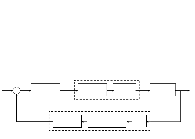
chattering phenomenon. The block diagram of the SMC by use of a machine vision system is
shown in Fig. 4, where the tracking error is
*
BB
ex x=− and the output displacements of
slider B are measured by a machine vision system, which includes the CCD, image
acquisition card and color pattern matching.
Toggle
Mechanism
PM Servo
Motor
Servo-amp
MR-J2S-40A
PM synchronous motor drive system
Sliding Mode
Controller
()
*
q
vU
r
θ
B
x
Image Acquisition
Card
CCD
Color Pattern
Matching
Machine Vision System
e
*
B
x
B
x
+
_
Fig. 4. Block diagram of the sliding mode control by the machine vision system.
3.3 Design of a fuzzy logic controller
In the real situations, the general problem encountered in designing a controller is that the
bounds of the uncertainties and exact mathematical models of the motor-toggle mechanism
system are difficult to obtain for practical applications. Moreover, the parameters can not be
obtained directly and the output responses of slider B must be able to measure. In this
chapter, the PD-type FLC (Rahbari & Silva, 2000) and PI-type FLC (Aracil & Gordillo, 2004),
which are without using complex mathematical model, are proposed to overcome the
difficulties of uncertainties and un-modeling.
3.3.1 The PD-type fuzzy logic controller
The control problem is to find the PD-type FLC law such that the output displacement x
B
can track the desired trajectories
*
B
x in the presence of uncertainties. Let the tracking error be
*
BB
ex x=− (38)
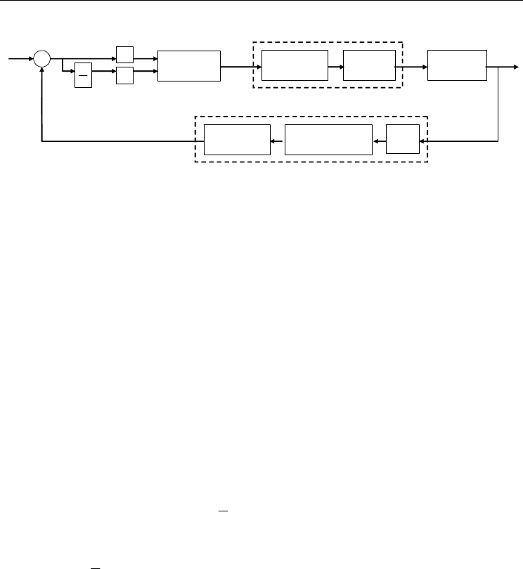
As shown in Fig. 5, the signals of e and e
are selected as the inputs for the proposed PD-
type FLC.
The control output of the PD-type FLC is u, which denotes the change of controller outputs.
The signals of e and e
could be respectively transferred to their corresponding universes of
discourse by multiplying scaling factors
1
k and
2
k , namely,
Vision-Based Control of the Mechatronic System
105
Toggle
Mechanism
PM Servo
Motor
Servo-amp
MR-J2S-40A
PM sync
h
ronous motor
d
r
i
ve syste
m
()
*
q
vU
r
θ
B
x
Image Acquisition
Card
CCD
Color Pattern
Matching
Machine Vision System
*
B
x
B
x
+
_
1
k
2
k
Fuzzy Logic
Controller
e
e
e
E
e
E
dt
d
Fig. 5. Block diagram of a PD-type FLC for the motor-toggle mechanism.
1e
Eek=∗ ,
2e
Eek=∗ (39)
Since the output u of the FLC is in its corresponding universe of discourse, the u could be
transferred, by multiplying a scaling factor
u
G , to an actual input of the plant, namely,
u
UuG=∗ (40)
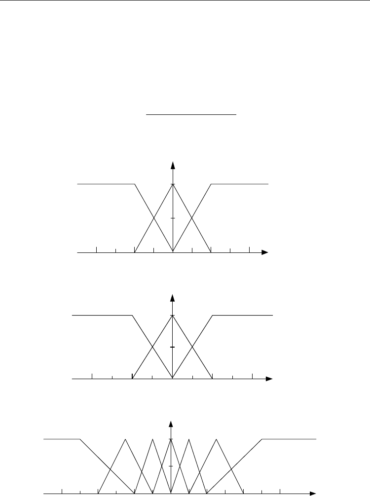
Because the data manipulation in the PD-type FLC is based on the fuzzy set theory, the
associated fuzzy sets involved in the linguistic control rules are defined as follows:
N: Negative Z: Zero P: Positive
NB: Negative Big NM: Negative Medium NS: Negative Small
ZE: Zero PS: Positive Small PM: Positive Medium PB: Positive Big
and their universe of discourse are all assigned to be [-10, 10] for a real experimental motor.
The membership functions for these fuzzy sets corresponding to
e
E ,
e
E
and u are defined
in Fig. 6.
In the following, the rule bases of the proposed PD-type FLC are systematically constructed
on the basis of a Lyapnuov function
f
L :
2
1
0
2
f
Le=≥
and
f
Lee=
(41)
According to Lyapnuov stable theory (Cheng & Tzou, 2004), if the system is stable, the
conditions
2
1
0
2
f
Le=≥
and ee
<0 are necessary. Therefore, according to Eq. (41), if e<0,
increasing u will result in decreasing ee
; if e>0, decreasing u will result in decreasing ee
.
Hence, the control input u can be designed in an attempt to satisfy the condition ee
<0. The
resulting fuzzy control rules are shown in the following:
Rule 1: If E
e
is P and
e
E
is P Then u is NB
Rule 2: If E
e
is P and
e
E
is Z Then u is NM
Rule 3: If E
e
is P and
e
E
is N Then u is NM
Rule 4: If E
e
is Z and
e
E
is P Then u is NS
Rule 5: If E
e
is Z and
e
E
is Z Then u is ZE
Visual Servoing
106
Rule 6: If E
e
is Z and
e
E
is N Then u is PS
Rule 7: If E
e
is N and
e
E
is P Then u is PM
Rule 8: If E
e
is N and
e
E
is Z Then u is PM
Rule 9: If E
e
is N and
e
E
is N Then u is PB.
By using the centre-of-area (COA) method, the output can be obtained as
(())(())
(( ( ))( ( )))
ij
ij
kA B
AB
uueue
u
ueue
⎡
⎤
⎢
⎥
⎣
⎦
=
∑
∑
. (42)
024
-2
-4
N
Z
P
1
0.5
SE
e
,
μ
024
-2
-4
N
Z
P
1
0.5
SE
e
,
μ
024
-2
-4
NB ZE
PB
1
u
u
μ
NM NS PMPS
-6
6
Fig. 6. Membership functions of , , , and .
ee
ESES u
Vision-Based Control of the Mechatronic System
107
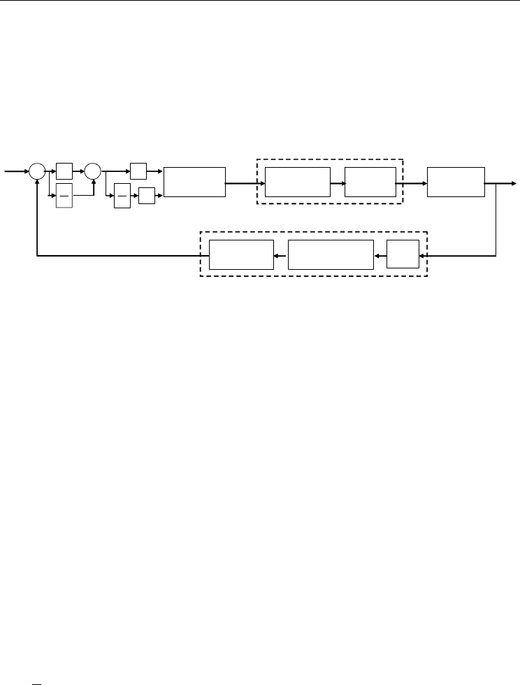
3.3.2 The PI-type fuzzy logic controller
In this section, the proposed PI-type FLC is designed based on the concept of hitting switch
conditions. As shown in Fig. 7, the switching functions are selected as the inputs. In practical
implementation, it can be approximated by
()(( 1))/skT sk T T=−
, (43)
where k is the number of iteration and T is the sampling period.
Toggle
Mechanism
PM Servo
Motor
Servo-amp
MR-J2S-40A
PM synchronous motor drive syste
m
()
*
q
vU
r
θ
B
x
Image Acquisition
Card
CCD
Color Pattern
Matching
Machine Vision S
y
ste
m
*
B
x
B
x
+
_
Fuzzy Logic
Controller
e
e
dt
d
S
S
s
s
dt
d
s
G
s
G
Δ
C
+
+
Fig. 7. Block diagram of a PI-type FLC for the motor-toggle mechanism.
The control input of the PI-type FLC is u which denotes the change of the controller outputs.
The s and s
signals could be transferred to their corresponding universes of discourse by
multiplying scaling factors G
s
and G
Δ
s
respectively, namely,
,.
ss
SsG SsG
Δ
=⋅ =⋅
(44)
Since the output u of the PI-type FLC is in its corresponding universe of discourse, the u
could be transferred, by multiplying a scaling factor G
Δ
u
, to an actual input of the plant,
namely,
.
u
UuG
Δ
Δ=⋅ (45)
Because the data manipulation in a PI-type FLC is based on fuzzy set theory, the associated
fuzzy sets involved in the linguistic control rules are defined as the same as the previous
section and their universe of discourse are all assigned the same as the previous section. The
membership functions for these fuzzy sets corresponding to , and .SS u
are also defined
in Fig. 6.
In the following, the rule base of the proposed PI-type FLC are systematically constructed
on the basis of hitting switching conditions of the SMC. Multiplying of Eq. (43) by s then we
have
.ss fs GUs ds vs Ces=+ +−+
(46)
It is similar to the PD-type FLC, Lyapunov function for the PI-type FLC is assigned as
2
1
0
2
f
Ls=≥
. The controller is designed to satisfy the condition ss
<0, and the whole
control system is stable. According to Eq. (44), if s < 0, increasing u will result in decreasing;
if s > 0, decreasing u will result in decreasing ss
. Hence, the control input u can be designed
in an attempt to satisfy the hitting condition ss
<0.

Visual Servoing
108
The resulting PI-type FLC rules are shown as follows:
Rule 1: If S is P and
S
is P Then u is NB
Rule 2: If S is P and
S
is Z Then u is NM
Rule 3: If S is P and
S
is N Then u is NM
Rule 4: If S is Z and
S
is P Then u is NS
Rule 5: If S is Z and
S
is Z Then u is ZE
Rule 6: If S is Z and
S
is N Then u is PS
Rule 7: If S is N and
S
is P Then u is PM
Rule 8: If S is N and
S
is Z Then u is PM
Rule 9: If S is N and
S
is N Then u is PB.
By using the centre-of-area (COA) method, the output can be obtained as
( ( ))( ( ))
(( ( ))( ( )))
ij
ij
kF G
FG
uueue
u
ueu e
⎡
⎤
⎢
⎥
⎣
⎦
=
∑
∑
. (47)
In this chapter, the mean of maximum (MOM) of defuzzifier is adopted in both the PD-type
and PI-type FLCs.
4. Numerical simulations
For numerical simulations, the parameters of the mechatronic system of the motor-toggle
mechanism are chosen as follows:
4.12 K ,
B
mg= 5.58 K ,
C
mg=
2
1.82 K ,mg=
3
1.61 K ,mg=
5
0.95 K ,mg= 0.17,
μ
=
1
0.06 ,rm=
2
0.032 ,rm=
3
0.06 ,rm=
4
0.068 ,rm=
5
0.03 ,rm= 0.068 ,hm=
0.4899 ,rad
φ
= 0.5652 / ,
t
KNmA=
52
6.7 10 ,
m
JNms
−
=× and
2
1.12 10 / .
m
BNmsrad
−
=×
The above known parameters are to substitute into Eq. (7), and the system becomes an
initial value problem and can be integrated by using the fourth-order Runge-Kutta method
with time step
0.001 sectΔ= and tolerance error 10
-9
. The control objective is to control the
position of slider
B to move from the left side to the right side. The initial position is 0.06 m,
the desired position is 0.1 m, and the controlled stroke of the slider
B is equal to
0.04
B
xmΔ= .
4.1 Numerical simulations of adaptive controller
For numerical simulations, the external disturbance force
E
F
will be added to test the
robustness of the adaptive controller. The gains of the adaptive control law (18) are given as
follows:
12
10, 194, 248 173.
eV
Kand
λγγ
=== = They are chosen to achieve the best
transient performance in the limitation of control effort and the requirement of stability. In
the real system, the angles of
1
θ
,
2
θ
, and
5
θ
are limited in the following ranges:
1
23 63
θ
°°
<< ,
2
325 350
θ
°°
<< , and
5
145 170
θ
°°
<< . Therefore, the invertible property of
1
ˆ
−
Q can be guaranteed and the system function
1
ˆ
ˆ
(;) 0ft
−
=>XQMcan be proved.
Vision-Based Control of the Mechatronic System
109
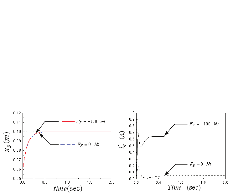
The dynamic responses of slider B and the control efforts
*
q
i
with and without external
disturbance force are compared in Figs. 8(a) and 8(b), respectively. The dotted lines are the
desired positions, the dash lines are the transient responses of numerical simulations with
external disturbance force
F
E
= 0 Nt and the solid lines are for F
E
= -100 Nt. The negative sign
in the external disturbance force indicates the action direction is opposite to the X-direction
in Fig. 1(a). In Fig. 8(a), the transient responses are almost the same and are stable after 0.5
sec and the steady-state error is about 1×10
-5
m
. Since the transient responses are almost the
same in the presence of uncertainties, it shows the proposed adaptive control is robust. In
Fig. 8(b), the maximum control effort
*
0.218
q
iA= for 0
E
FNt= is smaller than that
*
0.710
q
iA= for F
E
= -100 Nt.
(a) (b)
Fig. 8. The numerical simulations of a motor-toggle mechanism by an adaptive controller
with and without external disturbance forces. (a) The dynamic responses of the slider B.
(b) The control efforts
*
q
i .
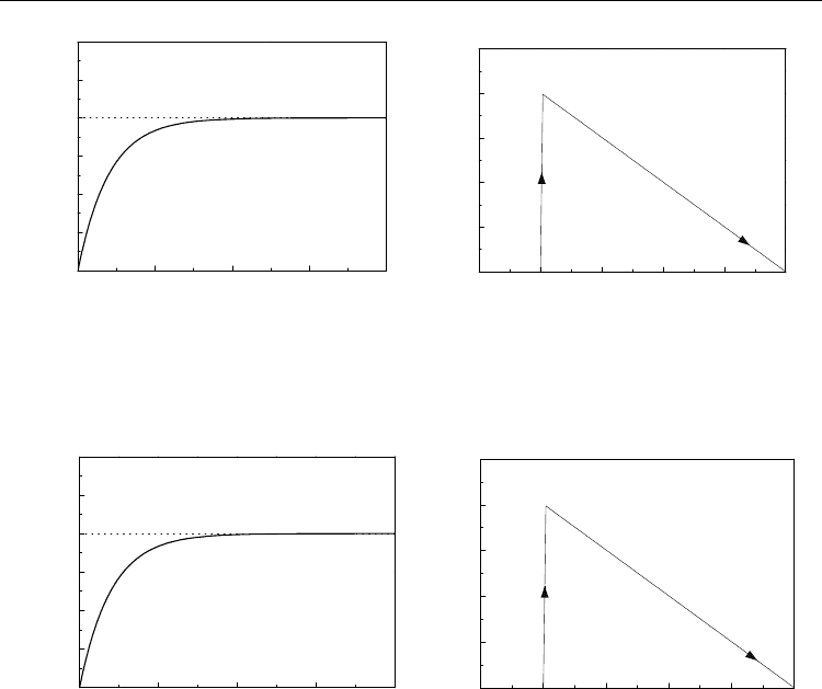
4.2 Numerical simulations of sliding mode controller
The nominal case is the system without external disturbance force, i.e.,
0
E
FNt=
and the
gains of the SMC are given as C=5 and 0.3
ε
= . The dynamic responses of slider B for the
nominal case are shown in Fig. 9 (a), and it is seen that the response is stable after 1 sec, and
the numerical error is about 0.01mm. The trajectories in the phase plane
(e, e)
are shown in
Fig. 9 (b), where the representative point lies on the designed sliding surface after it hits the
switching hyperplane.
Another case with external disturbance force
F
E
= 100 Nt is also considered and the
simulation results are shown in Figs. 10(a) and 10(b) for its dynamic responses and
trajectories, respectively. It is found that the smooth step-command tracking responses are
also obtained well and the SMC is robust to the presence of uncertainties.
Visual Servoing
110
0.0 0.5 1.0 1.5 2.0
0.06
0.07
0.08
0.09
0.10
0.11
0.12
(sec)time
)(mx
B
)(me
)/( sme
-0.05 -0.04 -0.03 -0.02 -0.01 0.00
0.00
0.05
0.10
0.15
0.20
0.25
(a) (b)
Fig. 9. (a) The dynamic responses of slider B by the SMC with
0
E
FNt= ;
(b) The trajectories in the phase plane by the SMC with
0
E
FNt= .
0.0 0.5 1.0 1.5 2.0
0.06
0.07
0.08
0.09
0.10
0.11
0.12
(sec)time
)(mx
B
)(me
)/( sme
-0.05 -0.04 -0.03 -0.02 -0.01 0.00
0.00
0.05
0.10
0.15
0.20
0.25
(a) (b)
Fig. 10. (a) The dynamic responses of slider B by the SMC with
100
E
FNt= ;
(b)The trajectories in the phase plane by the SMC with
100
E
FNt= .
4.3 Numerical simulations of the PD-type fuzzy logic controller
Here, the PD-type FLC is applied to control the motor-toggle mechanism system
numerically. In order to minimize the hitting time and track stable, the scaling factors are
determined by observing numerical simulations and are selected as
1
1082k = ,
2
849k = and
0.5
u
G = . Simulation results of the nominal case without external disturbance force are
shown in Fig. 11(a), where the dynamic responses are stable after 1.25 sec, and the error
between the desired position and numerical response of slider B is about 0.3 mm. Figure
11(b) illustrates the dynamic responses of the case with external disturbance force
F
E
= 100
Nt. It is seen that the responses are stable after 1.25 sec and the error is about 0.5 mm.
In conclusion, the responses of the PD-type FLC for a motor-toggle mechanism exhibit
overshoot phenomenon, and the affection of external disturbance forces to the system is
influenced. Therefore, the performance of the proposed PD-type FLC is not robust.