Grace Robert. Advanced Blowout and Well Control
Подождите немного. Документ загружается.

306
Advanced
Blowout
and
Well
Control
’1
Pbkl
=<(D;-q.’)[
O.7S54Sm2
-
O.3927Sre
s,‘
PMl
=
(105000)(2.375’
-
1.867’)
1
0.7854(73.79’) -0.3927(31.12’)
73. 7g2
Pfil
=
161,907
lbf
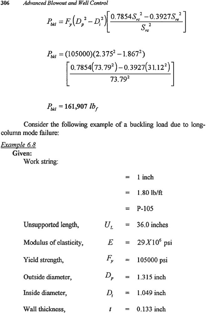
Consider the
following
example
of
a buckling
load
due
to
long-
column mode failure:
Example
6.8
Given:
Work
string:
Unsupported length,
ur.
Modulus
of
elasticity,
E
Yield strcngth,
Fy
Outside
diameter,
DP
Inside diameter,
Di
Wall thickness,
t
=
linch
=
1.80lbKt
=
P-105
=
36.0
inches
=
29X106
psi
=
105000psi
=
1.315inch
=
1.049 inch
=
0.133 inch
Special
Services
in
Well
Control
307
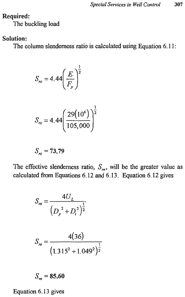
Required:
The buckling
load
Solution:
The column slenderness ratio
is
calculated using Equation 6.11
:
1
-
s,=
=
4.44(3
1
105,000
sm
=
73.79
The effective slenderness ratio,
S,,
will
be
the
greater value
as
calculated
from
Equations 6.12 and 6.13. Quation 6.12 gives
1
s,
=
4UL
(Di
+
Dj2):
1
4(34
s,
=
(1.3
15’
+
1.049*)2
S,
=
85.60
Eguation 6.13 gives
308
Advanced
Blowout
and
Well
Control
1
1
-
1.049
+
0.133 1.049
+
0.133
450(0.133)
)[
Z(0.133)
)
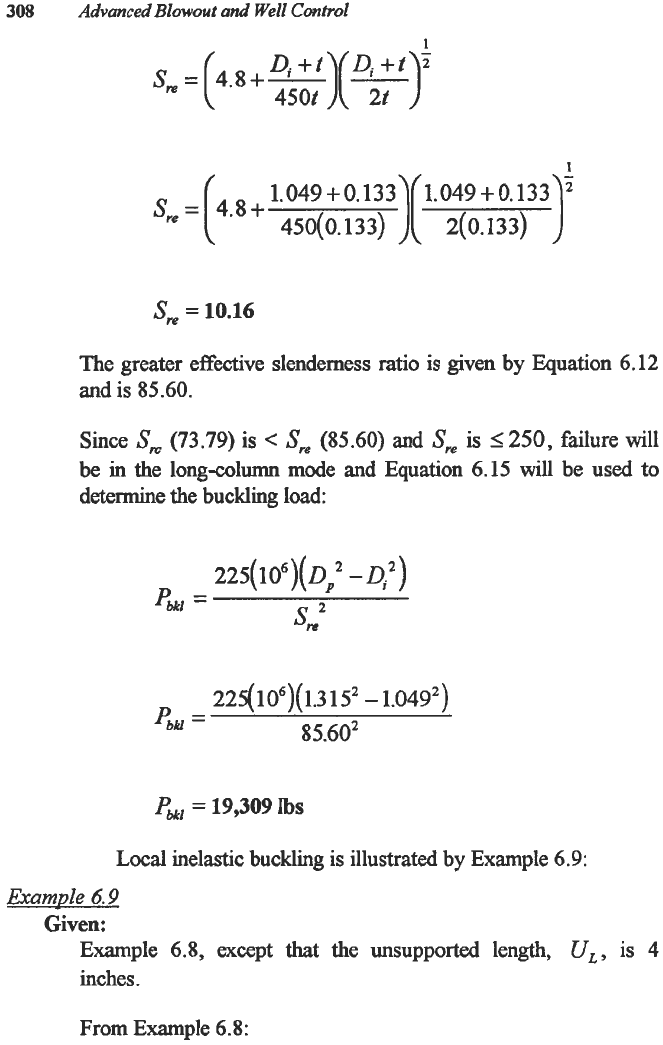
S,
=
10.16
The greater effective slenderness ratio is given by Equation
6.12
and
is
85.60.
Since
S,
(73.79)
is
<
SW
(85.60)
and
Sre
is
1250,
failure will
be
in
the long-column mode and Equation
6.15
will be used to
determine the buckling load:
225(
1
06)(
0,”
-
D:)
PMI
=
ZZ5(106)(
1.3
1S2
-
1.04g2)
85.602
4kJ
=
PMl
=
19,309
Ibs
Local
inelastic buckling is illustrated by Example
6.9:
Example
6.9
Given:
Example
6.8,
except that the unsupported length,
U,,
is
4
inches.
From Example
6.8:
Special
Services
in
Well
Control
309
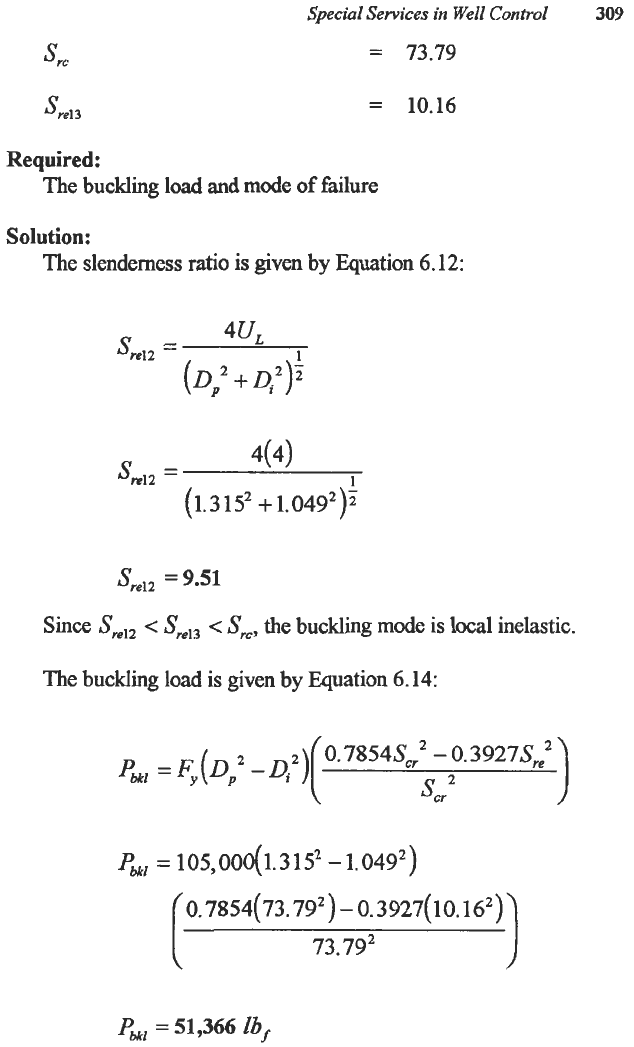
=
73.79
're1
3
=
10.16
Required:
The buckling load and mode
of
failure
Solution:
The slenderness ratio is
given
by Equation
6.12:
1
44
Sre12
=
(Di
+
4'):
1
4(4)
SmlZ
=
(1.3
1
5,
+
1,
04g2)?
S,,,,
=
9.51
Since
S,,,
<
Sm13
.e
S,,
the buckling mode
is
local
inelastic.
The buckling
load
is given by Equation
6.14:
Pbkl
=
F,(Di
-Q2)
(0.7854Scr~-$. 3927Sre
PMl
=
105,000(1.3
15'
-
1.
049,)
0.7854(
73.
79,)
-
0.3927(
10.
16,)
73.
79,
PMl
=
51,366
lbf
310
Advanced Blowout and Well
Control
FIRE FIGHTING AND CAPPING
Wild well fighting is more art
than
science. Each individual wild
well fighter may have
a
unique approach to any problem well. However,
in
the past
50
years, general approaches and equipment applications have
evolved. Although some unique specialty may apply
to
a particular
situation, the general approach is
to
remove the remnants of the rig and
well until the fire is burning through one orifice straight into the air.
Fipe
6
I7
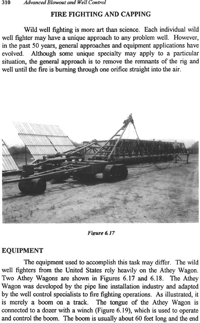
EQUIPMENT
The equipment used to accomplish
this
task
may differ. The wild
well fighters from the United States rely heavily on the Athey Wagon.
Two Athey Wagons are shown in Figures
6.17
and
6.18.
The Athey
Wagon was developed by the pipe line installation industry and adapted
by the well control specialists
to
fire fighting operations.
As
illustrated, it
is
merely a boom on
a
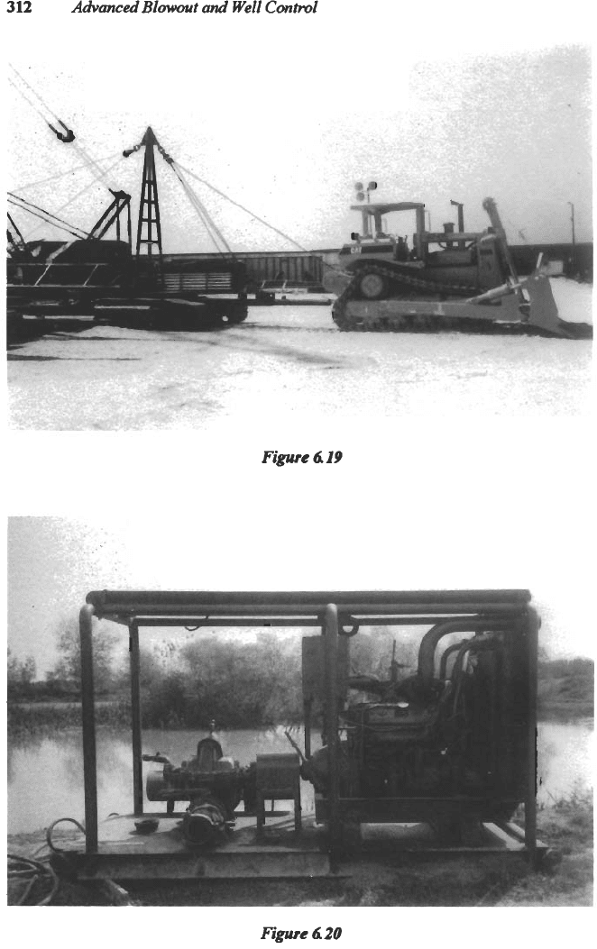
track. The tongue
of
the Athey Wagon
is
connected
to
a
dozer with a winch (Figure
6.19),
which
is
used to operate
and control the boom. The boom
is
usually about
60
feet
long and the end
Special Services in
Well
Control
3
1
1
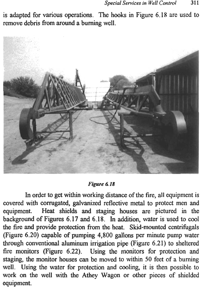
is adapted for various operations. The hooks in Figure
6.18
are used to
remove debris from around
a
burning well.
Figure
6
18
In
order
to
get within working
distance
of
the fire,
all
equipment is
covered with corrugated, galvanized reflective metal to protect men and
equipment. Heat shields and staging houses are pictured in the
background of Figures
6.17
and
6.18.
In
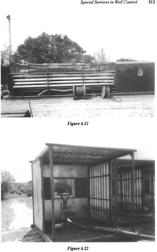
addition, water is used to
cool
the fire and provide protection from the heat. Skid-mounted centrifbgals
(Figure
6.20)
capable of pumping
4,800
gallons per minute pump water
through conventional aluminum irrigation pipe (Figure
6.21)
to sheltered
fire monitors (Figure
6.22).
Using the monitors for protection and
staging, the monitor houses
can
be
moved
to
within
50
feet of a burning
well. Using the water for protection and cooling, it is then possible to
work on the well with the Athey Wagon or other pieces
of
shielded
equipment.
312
Advanced
Blowout
and
Well
Contml
figure
419
Figure
420
Special Services in Well
Control
313
Figure
6
21
Figure
6
22
314
Advanced Blowout and Well Control
EXTINGUISHING THE FIRE
Some wells, such as those with toxic concentrations of hydrogen
sulfide, are capped with the fire burning.
In most
instances,
the fire is
extinguished prior to the capping operation. The fire is usually
extinguished with water, water in combination with fire extinguishing
additives or explosives.
In many instances, several monitors are concentrated on the base
of the fire and
cool
the fire to the extent that the fire will no longer bum.
The fire-suppressing chemicals such
as
those found in ordinary fire
extinguishers significantly increase the effectiveness
of
the water.
Wild well fighters are noted for the use of explosives to extinguish
a fire. Generally, between
100
and
1,000
pounds, with the lower end
being the most common, of dynamite are used although plastic explosives
such as
C4
are also used. The dynamite is placed into a 55-gallon drum.
Fire-retarding chemicals are often included. The drum is wrapped with
insulating material and placed on the end of the Athey Wagon boom. The
drum is positioned
at
the base of the plume and the dynamite is detonated.
The explosion robs the fire of oxygen. The fire monitors are used to cool
the area around the fire to prevent re-ignition.
CAPPING
THE
WELL
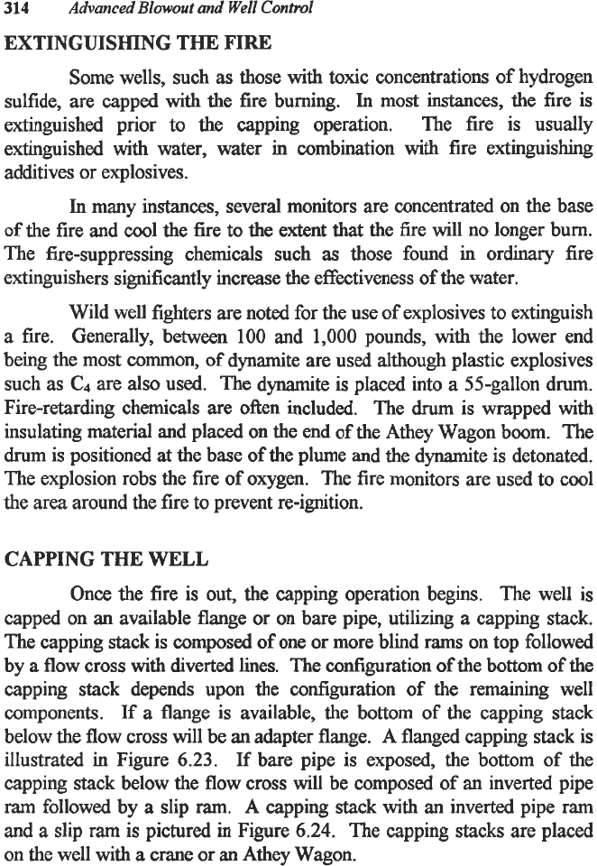
Once
the
fire is out, the capping operation begins. The well is
capped on
an
available flange or on bare pipe, utilizing a capping stack.
The capping stack is composed
of
one or more blind rams on top followed
by
a
flow cross with diverted lines. The configuration
of
the bottom
of
the
capping
stack
depends upon the configuration of the remaining well
components.
If
a flange is available, the bottom
of
the capping stack
below the flow cross will be an adapter flange. A flanged capping stack is
illustrated in Figure
6.23.
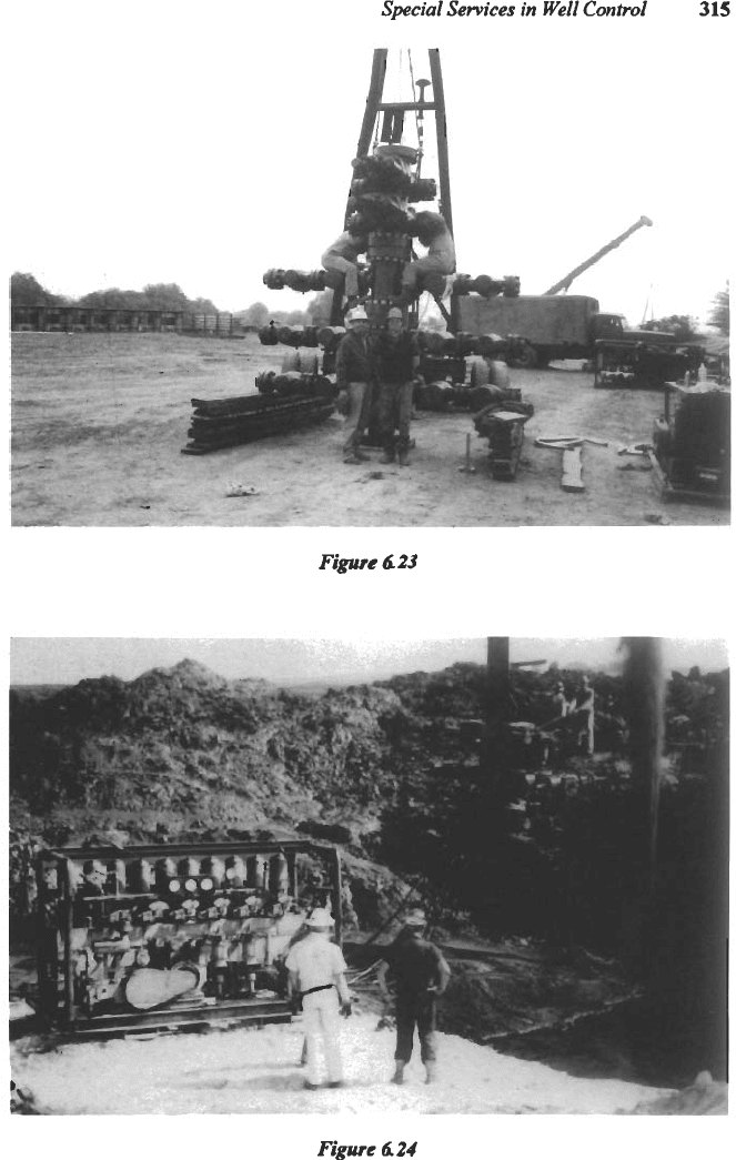
If
bare pipe is exposed, the bottom of the
capping stack below the flow cross will be composed of an inverted pipe
ram
followed by a slip
ram.
A
capping stack with an inverted pipe ram
and a slip
ram
is pictured in Figure 6.24. The capping stacks are placed
on the well with
a
crane or an Athey Wagon.
Special Services
in
Well Conh.01
315
Figure 423
-"*
Figure
4
24