Halliday D., Resnick R., Walker J. Fundamentals of physics. Test Bank
Подождите немного. Документ загружается.

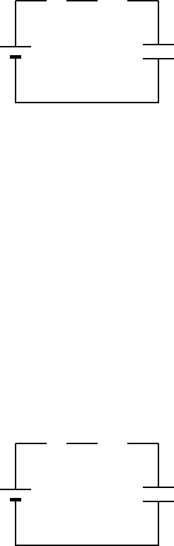
59. Four circuits have the form shown in the diagram. The capacitor is initially uncharged and the
switch S is open.
.
.
.
.
.
.
.
.
.
.
..
.
.
.
.
.
.
.
.
.
.
.
.
.
.
.
.
.
.
.
..
.
.
.
.
.
.
.
.
.
.
.
.
.
.
.
.
.
.
.
..
.
.
.
.
.
.
.
.
.
.
.
.
.
.
.
.
.
.
.
..
.
.
.
.
.
.
.
.
.
.
.
.
.
.
.
.
.
.
.
..
.
.
.
.
.
.
.
.
.
.
.
.
.
.
.
.
.
.
.
..
.
.
.
.
.
.
.
.
.
.
R
CE
.
.
.
.
.
.
.
.
.
.
.
.
.
.
.
.
.
.
.
.
.
.
.
.
.
.
.
.
.
.
.
.
.
.
.
.
.
.
.
.
.
.
.
.
.
.
••
S
The values of the emf E , resistance R, and capacitance C for each of the circuits are
circuit 1: E =18V,R =3Ω, C =1µF
circuit 2: E =18V,R =6Ω, C =9µF
circuit 3: E =12V,R =1Ω, C =7µF
circuit 4: E =10V,R =5Ω, C =7µF
Rank the circuits according to the current just after switch S is closed least to greatest.
A. 1, 2, 3, 4
B. 4, 3, 2, 1
C. 4, 2, 3, 1
D. 4, 2, 1, 3
E. 3, 1, 2, 4
ans: D
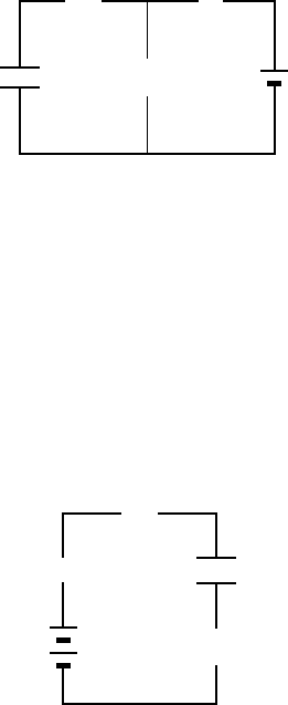
60. Four circuits have the form shown in the diagram. The capacitor is initially uncharged and the
switch S is open.
.
.
.
.
.
.
.
.
.
.
..
.
.
.
.
.
.
.
.
.
.
.
.
.
.
.
.
.
.
.
..
.
.
.
.
.
.
.
.
.
.
.
.
.
.
.
.
.
.
.
..
.
.
.
.
.
.
.
.
.
.
.
.
.
.
.
.
.
.
.
..
.
.
.
.
.
.
.
.
.
.
.
.
.
.
.
.
.
.
.
..
.
.
.
.
.
.
.
.
.
.
.
.
.
.
.
.
.
.
.
..
.
.
.
.
.
.
.
.
.
.
R
CE
.
.
.
.
.
.
.
.
.
.
.
.
.
.
.
.
.
.
.
.
.
.
.
.
.
.
.
.
.
.
.
.
.
.
.
.
.
.
.
.
.
.
.
.
.
.
••
S
The values of the emf E , resistance R, and capacitance C for each of the circuits are
circuit 1: E =18V,R =3Ω, C =1µF
circuit 2: E =18V,R =6Ω, C =9µF
circuit 3: E =12V,R =1Ω, C =7µF
circuit 4: E =10V,R =5Ω, C =7µF
Rank the circuits according to the time after switch S is closed for the capacitors to reach half
their final charges, least to greatest.
A. 1, 2, 3, 4
B. 4, 3, 2, 1
C. 1, 3, 4, 2
D. 1 and 2 tied, then 4, 3
E. 4, 3, then 1 and 2 tied
ans: C
Chapter 27: CIRCUITS 401
61. The time constant RC has units of:
A. second/farad
B. second/ohm
C. 1/second
D. second/watt
E. none of these
ans: E
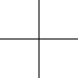
62. In the circuit shown, both resistors have the same value R. Suppose switch S is initially closed.
When it is then opened, the circuit has a time constant τ
a
. Conversely, suppose S is initially
open. When it is then closed, the circuit has a time constant τ
b
. The ratio τ
a
/τ
b
is:
.
.
.
.
.
.
.
.
..
.
.
.
.
.
.
.
.
.
.
.
.
.
.
.
..
.
.
.
.
.
.
.
.
.
.
.
.
.
.
.
..
.
.
.
.
.
.
.
.
.
.
.
.
.
.
.
..
.
.
.
.
.
.
.
.
.
.
.
.
.
.
.
..
.
.
.
.
.
.
.
.
.
.
.
.
.
.
.
..
.
.
.
.
.
.
.
.
R
.
.
.
.
.
.
.
.
..
.
.
.
.
.
.
.
.
.
.
.
.
.
.
.
..
.
.
.
.
.
.
.
.
.
.
.
.
.
.
.
..
.
.
.
.
.
.
.
.
.
.
.
.
.
.
.
..
.
.
.
.
.
.
.
.
.
.
.
.
.
.
.
..
.
.
.
.
.
.
.
.
.
.
.
.
.
.
.
..
.
.
.
.
.
.
.
.
RC
.
.
.
.
.
.
.
.
.
.
.
.
.
.
.
.
.
.
.
.
.
.
.
.
.
.
.
.
.
.
.
.
.
.
.
.
.
S
E
•
•
A. 1
B. 2
C. 0.5
D. 0.667
E. 1.5
ans: B
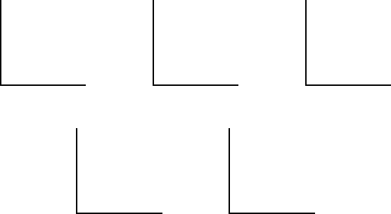
63. In the circuit shown, the capacitor is initially uncharged. At time t = 0, switch S is closed. If
τ denotes the time constant, the approximate current through the 3 Ω resistor when t = τ/10
is:
.
.
.
.
.
.
.
.
..
.
.
.
.
.
.
.
.
.
.
.
.
.
.
.
..
.
.
.
.
.
.
.
.
.
.
.
.
.
.
.
..
.
.
.
.
.
.
.
.
.
.
.
.
.
.
.
..
.
.
.
.
.
.
.
.
.
.
.
.
.
.
.
..
.
.
.
.
.
.
.
.
.
.
.
.
.
.
.
..
.
.
.
.
.
.
.
.
6 Ω
.
.
.
.
.
.
.
.
..
.
.
.
.
.
.
.
.
.
.
.
.
.
.
.
..
.
.
.
.
.
.
.
.
.
.
.
.
.
.
.
..
.
.
.
.
.
.
.
.
.
.
.
.
.
.
.
..
.
.
.
.
.
.
.
.
.
.
.
.
.
.
.
..
.
.
.
.
.
.
.
.
.
.
.
.
.
.
.
..
.
.
.
.
.
.
.
.
3 Ω10 V
.
.
.
.
.
.
.
.
.
.
.
.
.
.
.
.
.
.
.
.
.
.
.
.
.
.
.
.
.
.
.
.
.
.
.
.
.
.
.
.
.
•
•
S
6 µF
A. 0.38 A
B. 0.50 A
C. 0.75 A
D. 1.0A
E. 1.5A
ans: D
402 Chapter 27: CIRCUITS
64. Suppose the current charging a capacitor is kept constant. Which graph below correctly gives
the potential difference V across the capacitor as a function of time?
.
.
.
.
.
.
.
.
.
.
.
.
.
.
.
.
.
.
.
.
.
.
.
.
.
.
.
.
.
.
.
.
.
.
.
.
.
.
.
.
.
.
.
.
.
.
.
.
.
.
.
.
.
.
.
.
.
.
.
.
.
.
.
.
.
.
.
.
.
.
.
.
.
.
.
.
.
.
.
.
.
.
.
.
.
.
.
.
.
.
.
.
.
.
.
.
.
.
.
.
.
.
.
.
.
.
.
.
.
.
.
.
.
.
.
.
.
.
.
.
.
.
.
.
.
.
.
.
.
.
.
.
.
.
.
.
.
.
.
.
.
.
.
.
.
.
.
.
.
.
.
.
.
.
.
.
.
.
.
.
.
.
.
.
.
.
.
.
..
.
.
..
.
..
..
...
......
t
V
A
...............................................................................................................................
t
V
B
.
.
.
.
.
.
.
.
.
.
.
.
.
.
.
.
.
.
.
.
.
.
.
.
.
.
.
.
.
.
.
.
.
.
.
.
.
.
.
.
.
.
.
.
.
.
.
.
.
.
.
.
.
.
.
.
.
.
.
.
.
.
.
.
.
.
.
.
.
.
.
.
.
.
.
.
.
.
.
.
.
.
.
.
.
.
.
.
.
.
.
.
.
.
.
.
.
.
.
.
.
.
.
.
.
.
.
.
.
.
.
.
.
.
.
.
.
.
.
.
.
.
.
.
.
.
.
.
.
.
.
.
.
.
.
.
.
.
.
.
.
.
.
.
.
.
.
.
.
.
.
.
.
.
.
.
.
.
.
.
.
.
.
.
.
.
.
.
.
.
.
.
.
.
.
.
.
.
.
t
V
C
.....
...
...
.
..
..
.
.
.
.
.
.
.
.
.
.
.
.
.
.
.
.
.
.
.
.
.
.
.
.
.
.
.
.
.
.
.
.
.
.
.
.
.
.
.
.
.
.
.
.
.
.
.
.
.
.
.
.
.
.
.
.
.
.
.
.
.
.
.
.
.
.
.
.
.
.
.
.
.
.
.
.
.
.
.
.
.
.
.
.
.
.
.
.
.
.
.
.
.
.
.
.
.
.
.
.
.
.
.
.
.
.
.
.
.
.
.
.
.
.
.
.
.
.
.
.
.
.
.
.
.
.
.
.
.
.
.
.
.
.
.
.
.
.
.
.
.
.
.
.
.
.
.
.
.
.
.
.
.
.
.
.
.
.
.
.
.
.
.
.
.
.
.
.
.
.
.
.
t
V
D
.
.
.
.
.
.
.
.
.
.
.
.
.
.
.
.
.
.
.
.
.
.
.
.
.
.
.
.
.
.
.
.
.
.
.
.
.
.
.
.
.
.
.
.
.
.
.
.
.
.
.
.
.
.
.
.
.
.
.
.
.
.
.
.
.
.
.
.
.
.
.
.
.
.
.
.
.
.
.
.
.
.
.
.
.
.
.
.
.
.
.
.
.
.
.
.
.
.
.
.
.
.
.
.
.
.
.
.
.
.
.
.
.
.
.
.
.
.
.
.
.
.
.
.
.
.
.
t
V
E
ans: C
65. A charged capacitor is being discharged through a resistor. At the end of one time constant
the charge has been reduced by (1 − 1/e) = 63% of its initial value. At the end of two time
constants the charge has been reduced by what percent of its initial value?
A. 82%
B. 86%
C. 100%
D. Between 90% and 100%
E. Need to know more data to answer the question
ans: B
66. An initially uncharged capacitor C is connected in series with resistor R. This combination is
then connected to a battery of emf V
0
.Sufficient time elapses so that a steady state is reached.
Which of the following statements is NOT true?
A. The time constant is independent of V
0
B. The final charge on C is independent of R
C. The total thermal energy generated by R is independent of R
D. The total thermal energy generated by R is independent of V
0
E. The initial current (just after the battery was connected) is independent of C
ans: C
67. A certain capacitor, in series with a resistor, is being charged. At the end of 10 ms its charge
is half the final value. The time constant for the process is about:
A. 0.43 ms
B. 2.3ms
C. 6.9ms
D. 10 ms
E. 14 ms
ans: E
Chapter 27: CIRCUITS 403
68. A certain capacitor, in series with a 720-Ω resistor, is being charged. At the end of 10 ms its
charge is half the final value. The capacitance is about:
A. 9.6 µF
B. 14 µF
C. 20 µF
D. 7.2F
E. 10 F
ans: C
69. In the capacitor discharge formula q = q
0
e
−t/RC
the symbol t represents:
A. the time constant
B. the time it takes for C to lose the fraction 1/e of its initial charge
C. the time it takes for C to lose the fraction (1 − 1/e) of its initial charge
D. the time it takes for C to lose essentially all of its initial charge
E. none of the above
ans: E
404 Chapter 27: CIRCUITS
Chapter 28: MAGNETIC FIELDS
1. Units of a magnetic field might be:
A. C·m/s
B. C·s/m
C. C/kg
D. kg/C·s
E. N/C·m
ans: D
2. In the formula
F = qv ×
B:
A.
F must be perpendicular to v but not necessarily to
B
B.
F must be perpendicular to
B but not necessarily to v
C. v must be perpendicular to
B but not necessarily to
F
D. all three vectors must be mutually perpendicular
E.
F must be perpendicular to both v and
B
ans: E
3. An electron moves in the negative x direction, through a uniform magnetic field in the negative
y direction. The magnetic force on the electron is:
.............................................................................................................................................................................................................................................................
x
.
.
.
.
.
.
.
.
.
.
.
.
.
.
.
.
.
.
.
.
.
.
.
.
.
.
.
.
.
.
.
.
.
.
.
.
.
.
.
.
.
.
.
.
.
.
.
.
.
.
.
.
.
.
.
.
.
.
.
.
.
.
.
.
.
.
.
.
.
.
.
.
.
.
.
.
.
.
.
.
.
.
.
.
.
.
.
.
.
.
.
.
.
.
.
.
.
.
.
.
.
.
.
.
.
.
.
.
.
.
.
.
.
.
.
.
.
.
.
.
.
.
.
.
.
.
.
.
.
.
.
.
.
.
.
.
.
.
.
.
.
.
.
.
.
.
.
.
.
.
.
.
.
.
.
.
.
.
.
.
.
.
.
.
.
.
.
.
.
.
.
.
.
.
.
.
.
.
.
.
.
.
.
.
.
.
.
.
.
.
.
.
.
.
.
.
.
.
.
.
.
.
.
.
.
.
.
.
.
.
.
.
.
.
.
.
.
.
.
.
.
.
.
.
.
.
.
.
.
.
.
.
.
.
.
.
.
.
.
.
.
.
.
.
.
.
.
.
.
.
.
.
.
y
.
.
.
.
.
.
.
.
.
.
.
.
.
.
.
.
.
.
.
.
.
.
.
.
.
.
.
.
.
.
.
.
.
.
.
.
.
.
.
.
.
.
.
.
.
.
.
.
.
.
.
.
.
.
.
.
.
.
.
.
.
.
.
.
.
.
.
.
.
.
.
.
.
.
.
.
.
.
.
.
.
.
.
.
.
.
.
.
.
.
.
.
.
.
.
.
.
.
.
.
.
.
.
.
.
.
.
.
.
.
.
.
.
.
.
.
.
.
.
.
.
.
.
.
.
.
.
.
.
.
.
.
.
.
.
.
.
.
.
.
.
.
.
.
.
.
.
.
.
.
.
.
.
.
.
.
.
.
.
.
.
.
.
.
.
.
.
.
.
.
.
.
.
.
.
.
.
.
.
.
.
.
.
.
.
.
.
.
.
.
.
.
.
.
.
.
.
.
.
.
.
.
.
.
.
.
.
.
.
.
.
.
.
.
.
.
.
.
.
.
.
.
.
.
.
.
.
.
.
.
.
.
.
.
.
z
..........................................................................
..
.
.
.
.
.
.
.
.
.
.
.
.
.
.
.
.
.
.
.
.
.
..
.
.
.
.
.
.
.
.
.
.
.
.
.
.
.
.
.
.
v
.
.
.
.
.
.
.
.
.
.
.
.
.
.
.
.
.
.
.
.
.
.
.
.
.
.
.
.
.
.
.
.
.
.
.
.
.
.
.
.
.
.
.
.
.
.
.
.
.
.
.
.
.
.
.
.
.
.
.
.
.
.
.
.
.
.
.
.
.
.
.
.
..
.
.
.
.
.
.
.
.
.
.
.
.
.
.
.
.
.
.
.
.
.
.
.
.
.
.
.
.
.
.
.
.
.
.
.
.
.
.
.
.
.
.
.
B
•
A. in the negative x direction
B. in the positive y direction
C. in the negative y direction
D. in the positive z direction
E. in the negative z direction
ans: E
4. At any point the magnetic field lines are in the direction of:
A. the magnetic force on a moving positive charge
B. the magnetic force on a moving negative charge
C. the velocity of a moving positive charge
D. the velocity of a moving negative charge
E. none of the above
ans: E
Chapter 28: MAGNETIC FIELDS 405
5. The magnetic force on a charged particle is in the direction of its velocity if:
A. it is moving in the direction of the field
B. it is moving opposite to the direction of the field
C. it is moving perpendicular to the field
D. it is moving in some other direction
E. never
ans: E
6. A magnetic field exerts a force on a charged particle:
A. always
B. never
C. if the particle is moving across the field lines
D. if the particle is moving along the field lines
E. if the particle is at rest
ans: C
7. The direction of the magnetic field in a certain region of space is determined by firing a test
charge into the region with its velocity in various directions in different trials. The field direction
is:
A. one of the directions of the velocity when the magnetic force is zero
B. the direction of the velocity when the magnetic force is a maximum
C. the direction of the magnetic force
D. perpendicular to the velocity when the magnetic force is zero
E. none of the above
ans: A
8. An electron is moving north in a region where the magnetic field is south. The magnetic force
exerted on the electron is:
A. zero
B. up
C. down
D. east
E. west
ans: A
9. A magnetic field CANNOT:
A. exert a force on a charged particle
B. change the velocity of a charged particle
C. change the momentum of a charged particle
D. change the kinetic energy of a charged particle
E. change the trajectory of a charged particle
ans: D
406 Chapter 28: MAGNETIC FIELDS
10. A proton (charge e), traveling perpendicular to a magnetic fi eld, experiences the same force as
an alpha particle (charge 2e) which is also traveling perpendicular to the same fi eld. The ratio
of their speeds, v
proton
/v
alpha
, is:
A. 0.5
B. 1
C. 2
D. 4
E. 8
ans: C
11. A hydrogen atom that has lost its electron is moving east in a region where the magnetic field
is directed from south to north. It will be deflected:
A. up
B. down
C. north
D. south
E. not at all
ans: A
12. A beam of electrons is sent horizontally down the axis of a tube to strike a fluorescent screen
at the end of the tube. On the way, the electrons encounter a magnetic field directed vertically
downward. The spot on the screen will therefore be de fl ected:
A. upward
B. downward
C. to the right as seen from the electron source
D. to the left as seen from the electron source
E. not at all
ans: C
13. An electron (charge = −1.6 × 10
−19
C) is moving at 3 × 10
5
m/s in the positive x direction. A
magnetic field of 0.8 T is in the positive z direction. The magnetic force on the electron is:
A. 0
B. 4 × 10
−14
N, in the positive z direction
C. 4 × 10
−14
N, in the negative z direction
D. 4 × 10
−14
N, in the positive y direction
E. 4 × 10
−14
N, in the negative y direction
ans: D
14. At one instant an electron (charge = −1.6× 10
−19
C) is moving in the xy plane, the components
of its velocity being v
x
=5× 10
5
m/s and v
y
=3× 10
5
m/s. A magnetic field of 0.8 T is in the
positive x direction. At that instant the magnitude of the magnetic force on the electron is:
A. 0
B. 2.6 × 10
−14
N
C. 3.8 × 10
−14
N
D. 6.4 × 10
−14
N
E. 1.0 × 10
−13
N
ans: C
Chapter 28: MAGNETIC FIELDS 407
15. At one instant an electron (charge = −1.6× 10
−19
C) is moving in the xy plane, the components
of its velocity being v
x
=5× 10
5
m/s and v
y
=3× 10
5
m/s. A magnetic field of 0.8 T is in the
positive x direction. At that instant the magnitude of the magnetic force on the electron is:
A. 0
B. 3.8 × 10
−14
N
C. 5.1 × 10
−14
N
D. 6.4 × 10
−14
N
E. 7.5 × 10
−14
N
ans: B
16. An electron travels due north through a vacuum in a region of uniform magnetic field
B that
is also directed due north. It will:
A. be unaffected by the field
B. speed up
C. slow down
D. follow a right-handed corkscrew path
E. follow a left-handed corkscrew path
ans: A
17. At one instant an electron is moving in the positive x direction along the x axis in a region
where there is a uniform magnetic field in the positive z direction. When viewed from a point
on the positive z axis, it subsequent motion is:
A. straight ahead
B. counterclockwise around a circle in the xy plane
C. clockwise around a circle in the xy plane
D. in the positive z direction
E. in the negative z direction
ans: B
18. A uniform magnetic field is directed into the page. A charged particle, moving in the plane of
the page, follows a clockwise spiral of decreasing radius as shown. A reasonable explanation is:
.
.
.
.
.
.
.
.
.
.
.
.
.
.
.
.
.
.
.
.
.
.
.
.
.
.
.
.
.
.
.
.
.
.
.
.
.
.
.
.
.
.
.
.
.
.
.
.
.
.
.
.
.
.
.
.
.
.
.
.
.
.
.
.
.
.
.
.
.
.
.
.
.
.
.
.
.
.
.
.
.
.
.
.
.
.
.
.
.
.
.
.
.
.
.
.
.
.
.
.
.
.
.
.
.
.
.
.
.
.
.
.
.
.
.
.
.
.
.
.
..
.
.
..
..
..
..
...
....
...........
....
...
..
..
..
.
..
.
..
.
.
.
.
.
.
.
.
.
.
.
.
.
.
.
.
.
.
.
.
.
.
.
.
.
.
.
.
.
.
.
.
.
.
.
.
.
.
.
.
.
.
.
.
.
.
.
.
.
.
.
.
.
.
.
.
.
.
.
.
.
.
.
.
.
.
.
.
.
.
.
.
.
.
.
.
.
.
.
.
.
.
.
.
.
.
.
.
.
.
.
.
.
.
.
.
.
.
.
.
.
.
.
.
.
.
.
.
.
.
.
.
.
.
.
.
.
.
.
.
.
.
.
.
.
.
.
.
.
.
.
.
.
.
.
.
.
.
.
.
.
.
.
.
.
.
.
.
.
.
.
.
.
.
.
.
.
.
.
.
.
.
.
.
.
.
.
.
.
.
.
.
.
.
.
.
.
.
.
.
.
.
.
.
.
.
.
.
.
.
.
.
.
.
.
.
.
.
.
.
.
.
.
.
.
.
.
.
.
.
.
.
.
.
.
.
.
.
.
.
.
.
.
..
.
..
.
..
..
...
.....
.....
.....
...
..
..
..
.
.
..
.
.
.
.
.
.
.
.
.
.
.
.
.
.
.
.
.
.
.
.
.
.
.
.
.
.
.
.
.
.
.
.
.
.
.
.
.
.
.
.
.
.
.
.
.
.
.
.
.
.
.
.
.
.
.
.
.
.
.
.
.
.
.
.
.
.
.
.
.
.
.
.
.
.
.
.
.
.
.
.
.
.
.
.
.
.
.
.
.
.
.
.
.
.
.
.
.
.
.
.
.
.
.
.
.
.
.
.
.
.
.
.
.
.
.
.
.
.
.
.
.
.
.
.
.
.
.
.
.
.
.
.
.
.
.
.
.
.
.
.
.
.
.
.
.
.
.
.
.
.
.
.
.
.
.
.
.
.
.
.
.
.
.
.
.
.
.
.
.
.
.
.
.
.
.
.
.
.
.
.
.
.
.
.
.
.
.
.
.
.
.
.
..
..
.
...
...
............
...
..
..
..
.
..
.
.
.
.
.
.
.
.
.
.
.
.
.
.
.
.
.
.
.
.
.
.
.
.
.
.
.
.
.
.
.
.
.
.
.
.
.
.
.
.
.
.
.
.
.
.
.
.
.
.
.
.
.
.
.
.
.
.
.
.
.
.
.
.
.
.
.
.
.
.
.
.
.
.
.
.
.
.
.
.
.
.
.
.
.
.
.
.
.
.
.
.
.
.
.
.
.
.
.
.
.
.
.
.
.
.
.
.
.
.
.
.
.
.
.
.
.
.
.
.
.
.
.
.
.
.
.
.
.
.
.
.
.
.
.
.
.
.
.
.
.
.
.
.
.
.
.
.
.
.
.
.
.
.
.
.
.
.
.
.
.
..
..
..
...
........
...
..
..
.
..
.
.
.
.
.
.
.
.
.
.
.
.
.
.
.
.
.
.
.
.
.
.
.
.
.
.
.
.
.
.
.
.
.
.
.
.
.
.
.
.
.
.
.
.
.
.
.
.
.
.
.
.
.
.
.
.
.
.
.
.
.
.
.
.
.
.
.
.
.
.
.
.
.
.
.
.
.
.
.
.
.
.
.
.
.
.
.
.
.
.
.
.
.
.
.
.
.
.
.
.
.
.
.
.
.
.
.
.
.
.
.
.
.
.
.
.
.
.
.
.
.
.
.
.
.
.
.
.
.
.
..
...
.......
...
..
..
.
.
..
.
.
.
.
.
.
.
.
.
.
.
.
.
.
.
.
.
.
.
.
.
.
.
.
.
.
.
.
.
.
.
.
.
.
.
.
.
.
.
.
.
.
.
.
.
.
.
.
.
.
.
.
.
.
.
.
.
.
.
.
.
.
.
.
.
.
.
.
.
.
.
.
.
.
.
.
.
.
.
.
.
.
.
.
.
.
.
.
.
.
.
.
.
.
.
..
...
...
...
..
.
.
.
.
.
.
.
.
.
.
.
.
.
.
.
.
.
.
.
.
.
.
.
.
.
.
.
.
.
.
.
.
.
.
.
.
.
.
.
.
.
.
.
.
.
.
.
.
.
.
.
.
.
.
.
.
.
.
.
.
.
.
.
.
.
.
..
.....
..
.
.
.
.
.
.
.
.
.
.
.
.
.
.
.
.
.
.
.
.
.
.
.
.
.
.
.
.
.
.
.
.
•
.
.
.
.
.
.
..
.
.
.
.
.
.
.
.
.
.
.
.
.
.
.
.
.
.
.
.
.
.
.
.
.
.
.
.
.
.
.
.
.
.
.
.
.
.
.
.
.
.
.
.
.
.
.
.
.
.
.
.
.
.
.
particle
⊗⊗⊗⊗
⊗⊗⊗⊗
⊗⊗⊗⊗
⊗⊗⊗⊗
B
A. the charge is positive and slowing down
B. the charge is negative and slowing down
C. the charge is positive and speeding up
D. the charge is negative and speeding up
E. none of the above
ans: B
408 Chapter 28: MAGNETIC FIELDS
19. An electron and a proton each travel with equal speeds around circular orbits in the same
uniform magnetic field, as shown in the diagram (not to scale). The field is into the page on
the diagram. Because the electron is less massive than the proton and because the electron is
negatively charged and the proton is positively charged:
....
...
..
..
.
..
.
.
.
.
.
.
.
.
.
.
.
.
.
.
.
.
.
.
.
.
.
.
.
.
.
.
.
.
.
.
.
.
.
.
.
.
.
.
.
.
.
.
.
.
.
.
.
.
.
.
.
.
.
.
.
.
.
.
.
.
.
.
.
.
.
.
.
.
.
.
.
.
.
.
.
.
.
.
.
.
.
.
.
.
.
.
.
.
.
.
.
.
.
.
.
.
.
.
.
.
.
.
.
.
.
.
.
.
.
.
.
.
.
.
.
.
.
.
.
.
.
.
.
.
.
.
.
.
.
.
.
.
.
.
.
.
.
.
.
.
.
.
.
.
..
.
..
...
.........
...
..
..
.
.
..
.
.
.
.
.
.
.
.
.
.
.
.
.
.
.
.
.
.
.
.
.
.
.
.
.
.
.
.
.
.
.
.
.
.
.
.
.
.
.
.
.
.
.
.
.
.
.
.
.
.
.
.
.
.
.
.
.
.
.
.
.
.
.
.
.
.
.
.
.
.
.
.
.
.
.
.
.
.
.
.
.
.
.
.
.
.
.
.
.
.
.
.
.
.
.
.
.
.
.
.
.
.
.
.
.
.
.
.
.
.
.
.
.
.
.
.
.
.
.
.
.
.
.
.
.
.
.
.
.
.
.
.
.
.
.
.
.
.
.
.
.
.
.
..
.
..
....
...
•
......
.....
...
..
...
..
..
.
..
.
..
.
.
.
..
.
.
.
.
.
.
.
.
.
.
.
.
.
.
.
.
.
.
.
.
.
.
.
.
.
.
.
.
.
.
.
.
.
.
.
.
.
.
.
.
.
.
.
.
.
.
.
.
.
.
.
.
.
.
.
.
.
.
.
.
.
.
.
.
.
.
.
.
.
.
.
.
.
.
.
.
.
.
.
.
.
.
.
.
.
.
.
.
.
.
.
.
.
.
.
.
.
.
.
.
.
.
.
.
.
.
.
.
.
.
.
.
.
.
.
.
.
.
.
.
.
.
.
.
.
.
.
.
.
.
.
.
.
.
.
.
.
.
.
.
.
.
.
.
.
.
.
.
.
.
.
.
.
.
.
.
.
.
.
.
.
.
.
.
.
.
.
.
.
.
.
.
.
.
.
.
.
.
.
.
.
.
.
.
.
.
.
.
.
.
.
.
.
.
.
.
.
.
.
.
.
.
.
.
.
.
.
.
.
.
.
.
.
.
.
.
.
.
.
.
.
.
.
.
.
.
.
.
.
.
.
.
.
.
.
.
.
.
.
.
.
.
.
.
.
.
.
.
.
.
.
.
.
.
.
.
.
.
.
.
.
.
.
.
.
.
.
.
.
.
.
.
.
.
.
.
.
.
.
.
.
.
.
.
.
.
.
.
.
.
.
.
.
.
.
.
.
.
.
.
.
.
.
.
.
.
.
.
.
.
.
.
.
.
.
.
.
.
.
.
.
.
.
.
.
.
.
.
.
.
.
..
.
.
..
.
..
.
..
..
..
...
...
....
..............
....
...
...
..
..
.
..
..
.
.
..
.
.
.
.
..
.
.
.
.
.
.
.
.
.
.
.
.
.
.
.
.
.
.
.
.
.
.
.
.
.
.
.
.
.
.
.
.
.
.
.
.
.
.
.
.
.
.
.
.
.
.
.
.
.
.
.
.
.
.
.
.
.
.
.
.
.
.
.
.
.
.
.
.
.
.
.
.
.
.
.
.
.
.
.
.
.
.
.
.
.
.
.
.
.
.
.
.
.
.
.
.
.
.
.
.
.
.
.
.
.
.
.
.
.
.
.
.
.
.
.
.
.
.
.
.
.
.
.
.
.
.
.
.
.
.
.
.
.
.
.
.
.
.
.
.
.
.
.
.
.
.
.
.
.
.
.
.
.
.
.
.
.
.
.
.
.
.
.
.
.
.
.
.
.
.
.
.
.
.
.
.
.
.
.
.
.
.
.
.
.
.
.
.
.
.
.
.
.
.
.
.
.
.
.
.
.
.
.
.
.
.
.
.
.
.
.
.
.
.
.
.
.
.
.
.
.
.
.
.
.
.
.
.
.
.
.
.
.
.
.
.
.
.
.
.
.
.
.
.
.
.
.
.
.
.
.
.
.
.
.
.
.
.
.
.
.
.
.
.
.
.
.
.
.
.
.
.
.
.
.
.
.
.
.
.
.
.
.
.
.
.
.
.
.
.
.
.
.
.
.
.
.
.
.
.
.
.
.
.
.
.
.
.
.
.
.
.
.
.
.
.
.
.
.
.
.
.
.
.
.
.
.
.
.
.
..
.
.
..
.
..
..
..
..
...
...
.....
.....
•
⊗
B
A. the electron travels clockwise around the smaller circle and the proton travels counter-
clockwise around the larger circle
B. the electron travels counterclockwise around the smaller circle and the proton travels clock-
wise around the larger circle
C. the electron travels clockwise around the larger circle and the proton travels counterclock-
wise around the smaller circle
D. the electron travels counterclockwise around the larger circle and the proton travels clock-
wise around the smaller circle
E. the electron travels counterclockwise around the smaller circle and the proton travels coun-
terclockwise around the larger circle
ans: A
20. An electron is launched with velocity v in a uniform magnetic field
B. The angle θ between
v and
B is between 0 and 90
◦
. As a result, the electron follows a helix, its velocity vector v
returning to its initial value in a time interval of:
A. 2πm/eB
B. 2πmv/eB
C. 2πmv sin θ/eB
D. 2πmv cos θ/eB
E. none of these
ans: A
21. An electron and a proton are both initially moving with the same speed and in the same
direction at 90
◦
to the same uniform magnetic field. They experience magnetic forces, which
are initially:
A. identical
B. equal in magnitude but opposite in direction
C. in the same direction and differing in magnitude by a factor of 1840
D. in opposite directions and differing in magnitude by a factor of 1840
E. equal in magnitude but perpendicular to each other.
ans: B
Chapter 28: MAGNETIC FIELDS 409
22. An electron enters a region of uniform perpendicular
E and
B fields. It is observed that the
velocity v of the electron is unaffected. A possible explanation is:
A. v is parallel to
E and has magnitude E/B
B. v is parallel to
B
C. v is perpendicular to both
E and
B and has magnitude B/E
D. v is perpendicular to both
E and
B and has magnitude E/B
E. the given situation is impossible
ans: D
23. A charged particle is projected into a region of uniform, parallel,
E and
B fields. The force on
the particle is:
A. zero
B. at some angle < 90
◦
with the field lines
C. along the field lines
D. perpendicular to the field lines
E. unknown (need to know the sign of the charge)
ans: B
24. A uniform magnetic field is in the positive z direction. A positively charged particle is moving
in the positive x direction through the field. The net force on the particle can be made zero
by applying an electric field in what direction?
A. Positive y
B. Negative y
C. Positive x
D. Negative x
E. Positive z
ans: B
25. An electron is traveling in the positive x direction. A uniform electric field
E is in the negative
y direction. If a uniform magnetic field with the appropriate magnitude and direction also
exists in the region, the total force on the electron will be zero. The appropriate direction for
the magnetic field is:
x
y
...........................................................
.
..
.
.
.
.
.
.
.
.
.
.
.
.
.
.
.
.
.
.
.
..
.
.
.
.
.
.
.
.
.
.
.
.
.
.
.
.
.
.
.
v
.
.
.
.
.
.
.
.
.
.
.
.
.
.
.
.
.
.
.
.
.
.
.
.
.
.
.
.
.
.
.
.
.
.
.
.
.
.
.
.
.
.
.
.
.
.
.
.
.
.
.
.
.
.
.
.
.
..
.
.
.
.
.
.
.
.
.
.
.
.
.
.
.
.
.
.
.
.
.
.
.
.
.
.
.
.
.
.
.
.
.
.
.
.
.
.
.
.
.
.
.
E
•
A. the positive y direction
B. the negative y direction
C. into the page
D. out of the page
E. the negative x direction
ans: C
410 Chapter 28: MAGNETIC FIELDS