Harris C.M., Piersol A.G. Harris Shock and vibration handbook
Подождите немного. Документ загружается.


minimizes the motion of the corners of the equipment and allows the most efficient
installation from the standpoint of space requirements and isolation efficiency.
If the isolators cannot be located so as to provide a center-of-gravity installa-
tion, then the system analysis is more difficult and more space must be allowed
around the equipment to accommodate rocking motion (i.e., rotational modes) of
the system. Finally, the isolators must be double-checked to ensure that they
are capable of withstanding the additional loads and motions from the non-
translational movement of the equipment. This is particularly true when the
center-of-gravity is a significant distance above or below the plane in which the
isolators are located. Rule of thumb: The distance between the isolator plane and
the center-of-gravity should be equal to or less than one-third of the minimum
spacing between isolators. This helps to minimize rocking of the equipment and
the resultant high stress in the isolators.
Weight and Center-of-Gravity of Supported Equipment. The weight and loca-
tion of the center-of-gravity of the supported equipment should be determined. The
location of the center-of-gravity is necessary for calculating the load supported on
each mount. It is best to keep the equipment at least satatically balanced [essentially
equal deflections on all isolators (see Fig. 32.17)]. The preferred approach is to use
the same isolator at all points, choosing isolator locations such that static loads (and
thus deflections) are equalized. If this is not practical, isolators of different load rat-
ings may be required at different support points on the equipment for optimum iso-
lation.The size of the equipment and the mass distribution are important in dynamic
analyses of the isolated system.
Space Available for Equipment Motion. The choice of an isolator may depend
on the space available (commonly called sway space) around a piece of equipment.
The spring constant of the isolator should be chosen carefully so that motion is kept
within defined space limits. The motion which must be considered is the sum of (1)
the static deflection due to the weight supported by the isolator, (2) the deflection
caused by the dynamic environment, and (3) the deflection due to any steady-state
acceleration (such as in a maneuvering aircraft).
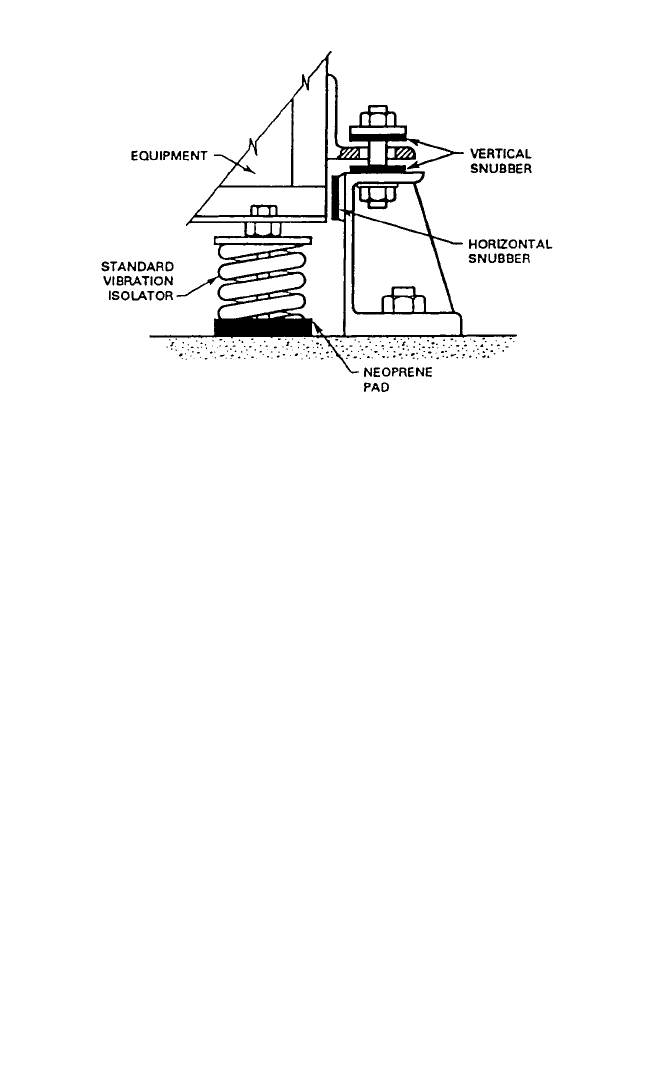
If there is a problem of excessive motion of the supported mass on the isolator,
then a snubber (i.e., a device which limits the motion) can be used.A snubber may be
an elastomeric compression element designed into an isolator. Captive-type isola-
tors (see Fail-Safe Installation) have built-in motion-limiting stops. Also, elastomers
stressed in compression have natural snubbing due to the nonlinear load-deflection
characteristics. In some cases it may be necessary to limit motion by separately
installed snubbers such as a compression pad at the point of excessive motion as
shown in Fig. 32.18. The spring constant of such a snubber must be carefully selected
to avoid transmission of high-impact loads into the supported equipment.
Ambient Environment. The environment in which an isolator is to be used
affects its selection in two ways:
1. Some environmental conditions may degrade the physical integrity of the isola-
tor and make it nonfunctional.
2. Some environmental conditions may change the operating characteristics of an
isolator, without causing permanent damage.
This may alter the characteristics of the isolation system of the supported equip-
ment; for example, frequency responses could change significantly with changes in
SHOCK AND VIBRATION ISOLATORS AND ISOLATION SYSTEMS 32.19
8434_Harris_32_b.qxd 09/20/2001 12:32 PM Page 32.19
the ambient temperature. Thus, it is important to determine the operating environ-
ment of the isolation system and to select isolators that will function with desired
characteristics in this environment.
Available Isolator Materials. Vibration and shock isolators are available in a
wide variety of materials and configurations to fit many different situations.The type
of isolator is chosen for the load and dynamic conditions under which it must oper-
ate. The material from which the isolator is made depends to a great extent on the
ambient environment of an application and somewhat on the dynamic properties
required. Guidance for the choice of isolator materials is given earlier in this chap-
ter. Chapter 33 describes the engineering properties of rubber.
Metal-spring isolators are used primarily where operating temperatures are too
high for elastomeric isolators. They can be used in a variety of applications.
By far, the majority of isolators in use today are elastomeric. The development
of a vast array of elastomeric compounds has made it possible to use this type of
isolator in almost any environment. Within a given type of elastomer, it is a simple
matter to vary the stiffness (modulus, durometer) of the compound; this gives much
flexibility in adapting an isolator to an application without changing the isolator’s
geometry.
Since the selection of material for an isolator depends so much on the environ-
ment in which the mount will be used, it is very important to learn as much as possi-
ble about the operating and storage environments.
Desired Service Life. The expected, or desired, length of service for an isolator
can affect the type and size of the vibration isolator which is selected. For example,
an isolator which must operate for 2000 hours under a given set of conditions typi-
cally is larger than one which must operate for only 500 hours under the same con-
ditions.
32.20 CHAPTER THIRTY-TWO
FIGURE 32.18 A vibration isolator provided with auxiliary elas-
tomeric snubbers to limit the motion of the isolator in the horizontal
and vertical directions; these snubbers provide a “cushion” stop to pro-
vide a lower shock force on the equipment than would be experienced
with a metal-to-metal stop.
8434_Harris_32_b.qxd 09/20/2001 12:32 PM Page 32.20

In general, empirical data are used to estimate the operating life of an isolator.
Accurate descriptions of the dynamic disturbances and ambient operating environ-
ment expected are needed to make an estimate of isolator life. A knowledge of the
specific material and design factors in an isolator is necessary to make an estimate of
fatigue life. Such information is best provided by the original manufacturer or
designer of the isolator.
Requirement for Fail-Safe Operation. Many pieces of equipment must be
mounted on isolators on which the equipment remains supported (in place) in the
event of mechanical failure of the isolator, i.e., until it can be replaced. This feature
may be provided by a metal-to-metal interlock, or it may be provided by snubbers,
as illustrated in Fig. 32.18.A snubber is a component in a resilient isolator which lim-
its the displacement of the isolator in the event of its failure.
Interaction with Support Structure. The support structure characteristics
can also affect the selection of isolators. An isolator must deflect if it is to isolate
vibration; generally the greater the deflection, the greater the isolation. The isolator
functions by being soft enough to allow relative vibration amplitudes without trans-
mitting excessive force to the support structure. It is often assumed, in the selection
of vibration isolators, that the support structure is a rigid mass with infinite stiffness.
This assumption is not true since if the foundation were infinitely stiff, it would not
respond to a dynamic force and the isolator would not be needed. Since the founda-
tion does respond to dynamic forces, its response must affect the components that
are flexibly attached to it. In reality the support structure is a spring in series with the
isolator (see Isolators in Combination above) and springs in series carry the same
force and deflect proportionally to their respective spring constants.Thus if the stiff-
ness of the isolator is high compared to the stiffness of the foundation, the founda-
tion will deflect more than the isolator and actually nullify or limit the isolation
provided from the isolator itself. To achieve maximum efficiency from the selected
isolator, the spring constant of the support structure should be at least 10 times that
of the spring constant of the isolator attached to it. This will assure that at least 90
percent of the total system spring constant is contributed by the isolators and only
10 percent by the support structure.
Because the structure supporting a piece of equipment has inherent flexibility, it
has resonances which could cause amplification of vibration levels; these resonance
frequencies must be avoided in relation to isolated system natural frequencies.
HOW TO SELECT ISOLATORS
The isolator selection process should proceed in the following steps:
Step 1. Required isolation efficiency. First, indicate the percentage of isolation
efficiency that is desired. In general, an efficiency of 70 to 90 percent is desirable and
is usually possible to attain.
Step 2. Transmissibility. From Table 32.1 determine the maximum transmissi-
bility T of the system at which the required vibration isolation efficiency of Step 1
will be provided.
Step 3. Forcing frequency. Determine the value of the lowest forcing frequency
f (i.e., the frequency of vibration excitation). For example, in the case of a motor, the
SHOCK AND VIBRATION ISOLATORS AND ISOLATION SYSTEMS 32.21
8434_Harris_32_b.qxd 09/20/2001 12:32 PM Page 32.21

forcing frequency depends on the rotational speed, given in revolutions per minute
(rpm); the rotational speed must be divided by 60 sec/minute to obtain the forcing
frequency in cycles per second (Hz). The lowest forcing frequency is used because
this is the worst condition, resulting in the lowest value of f/f
n
(see Table 32.1). If a
satisfactory value of isolation efficiency is attained at this frequency, the vibration
reduction at higher frequencies will be even greater.
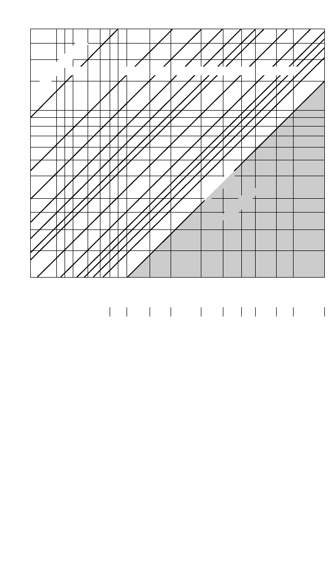
Step 4. Natural frequency. From Fig. 32.19, find the natural frequency f
n
of the
isolated system (i.e., the mass of the equipment supported on isolators) required to
provide a transmissibility T, determined in Step 2 (which is equivalent to a corre-
sponding percent vibration isolation efficiency) for a forcing frequency of f Hz
(determined in Step 3).
Step 5. Static deflection. From Fig. 32.19, determine the static deflection
required to provide a natural frequency of Step 4.
Step 6. Stiffness of isolation system. From Eq. (32.6), calculate the stiffness k
required to provide a natural frequency f
n
determined in Step 4:
f
n
= (32.6)
where W = the weight in pounds of the supported mass
g = the acceleration due to gravity in inches per second per second
Step 7. Stiffness of the individual vibration isolators. Determine the stiffness of
each of the n isolators from Eq. (32.4) or Eq. (32.5) depending on whether the vibra-
tion isolators are in parallel or in series. In general, they are in parallel so that the
required stiffness of each vibration isolator is 1/n times the value obtained in Step
6—assuming that all isolators share the load equally.
Step 8. Load on individual vibration isolators. Now calculate the load on each
individual isolator.
Step 9. Isolator selection. From a manufacturer’s catalog, elect a vibration iso-
lator which meets the stiffness requirement determined in Step 7 and which has a
load-carrying capacity (i.e., load rating) equal to the value obtained in Step 8. The
preferred approach is to use the same type and size isolator at all points of support;
[kg/W]
1/2
2π
32.22 CHAPTER THIRTY-TWO
TABLE 32.1 Ratio of ( f/f
n
) Required to Achieve
Various Values of Vibration Isolation Efficiency
Isolation Maximum
efficiency, % transmissibility Required f/f
n
90 0.1 3.32
80 0.2 2.45
70 0.3 2.08
60 0.4 1.87
50 0.5 1.73
40 0.6 1.63
30 0.7 1.56
20 0.8 1.50
10 0.9 1.45
0 1.0 1.41
8434_Harris_32_b.qxd 09/20/2001 12:32 PM Page 32.22
choose isolator locations such that static loads (and thus deflections) are equalized.
If this is not practical, isolators of different load ratings may be required at different
support points on the equipment. If the vibration occurs only in one direction, usu-
ally a simple isolator can be selected; its characteristics need be specified along only
one axis. In contrast, if the vibration is expected to occur along more than one direc-
tion, then the selected isolator must provide isolation along all the critical axes.
EXAMPLES
The following examples present specific applications. They show how isolators may
be selected for some simple shock and vibration problems, but the steps used are
basic and can be extended to many other situations. In the solution of these prob-
lems, the following simplifying assumptions are made:
SHOCK AND VIBRATION ISOLATORS AND ISOLATION SYSTEMS 32.23
3.1
50
41.7
33.2
25
16.7
15
13.3
11.7
10
8.3
6.7
5.0
4.2
3.3
2.5
1.7
1.6 .88
Natural frequency, f
n
, Hz
Static deflection δ
st
, inches
.39 .22 .14 .01 .055 .035 .0165.5
0.50
Forcing frequency, f, Hz
0.67
0.83
1.0
1.17
1.33
1.5
1.67
2.50
3.33
5.00
6.67
8.33
10.0
13.3
16.7
25
Amplification
Percent isolation
Resonance
99.9 9999.5 98 97 96 95 90 80 70 60
FIGURE 32.19 Isolation efficiency chart.The vibration efficiency, in percent, is given as a function
of natural frequency of the isolated system (along the horizontal axis) and the forcing frequency, i.e.,
the frequency of excitation (along the vertical axis). The use of this chart is restricted to applications
where the vibration isolators are supported by a floor structure having a vertical stiffness of at least
15 times the total stiffness of the isolation system. This may require that the isolated structure be
placed along the length of a floor beam or that an additional floor beam be added to the structure.
8434_Harris_32_b.qxd 09/20/2001 12:32 PM Page 32.23

1. The effect of damping is negligible, a valid assumption for many isolator applica-
tions.
2. All modes of vibration are uncoupled, i.e., the isolators are symmetrically located
with respect to the mass center-of-gravity.
3. The static and dynamic spring constants of the isolators are equal, valid for low
modulus elastomers with little damping.
Example 32.1: Vibration Isolation. When a shock or vibration disturbance orig-
inates in the supported equipment, isolators which support the equipment reduce
the transmission of force to the supporting structure, thus protecting the structure or
foundation, for example, in isolating a vehicle chassis from the vibration of an inter-
nal combustion engine or in reducing the transmission of machine vibration to adja-
cent structures.
Problem. An electric motor and pump assembly, rigidly mounted on a com-
mon base, rotates at a speed of 1800 rpm and transmits vibration to other compo-
nents of a hydraulic system. The weight of the assembly and base is 140 lb (63 kg).
Four isolators are to be located at the corners of the rectangular base. The center-
of-gravity is centrally located in the horizontal plane near the base. The lowest
vibratory forcing frequency is 1800 rpm and is a result of rotational unbalance.
There also are higher frequencies due to magnetic and pump forces. The excitation
is in both the horizontal and vertical directions.
Objective. To reduce the amount of vibration transmitted to the supporting
structure and thus to other system components.A vibration isolation efficiency of 70
to 90 percent is usually possible to attain.
Solution:
1. Select a vibration isolation efficiency midway between 70 and 90 percent, i.e.,
80 percent.
2. Find the transmissibility T which corresponds to an isolation efficiency of 80
percent. From Eq. (32.7) or Fig 32.19, this is a value of T = 0.2.
Isolation efficiency = 100(1 − T) in percent (32.7)
where T = transmissibility.
3. Determine the lowest forcing frequency f by dividing the rotational speed in
rpm by 60, yielding a value of 30 Hz.
4. Next calculate the natural frequency f
n
required to provide the transmissibil-
ity T = 0.2 for a forcing frequency f = 30 Hz. According to Eq. (32.8), this is a value
of 12.2 Hz.
T = (32.8)
where f = the forcing frequency (also called disturbing frequency) in Hz
f
n
= system natural frequency in Hz
5. Then calculate the static deflection required to provide a natural frequency of
12.2 Hz. According to Eq. (32.9), this is a value of δ
st
= 0.066 in. (1.67 mm).
1
( f/f
n
)
2
− 1
32.24 CHAPTER THIRTY-TWO
8434_Harris_32_b.qxd 09/20/2001 12:32 PM Page 32.24

f
n
= (32.9)
where δ
st
= the static deflection in inches
δ
st
= 0.066 in. (1.67 mm)
[The same results may be obtained by using the isolation efficiency chart, Fig.
32.19, as follows. Find the point at which the horizontal line for a forcing frequency
f = 30 Hz intersects the diagonal line for an isolation efficiency of 80 percent. From
the point of intersection, project a vertical line to read the values of δ
st
= 0.066 in.
(1.67 mm).]
6. Determine the stiffness of the required isolation system (i.e., combination of
four isolators) required to provide a natural frequency of f
n
. According to Eq.
(32.6), the value of stiffness of the system, for a weight of 140 lb, is 2120 lb/in. (371
N/mm).
7. Calculate the stiffness of individual isolators if one is placed in each corner by
dividing the value for the combination of isolators by 4, since all four support the
load.
8. The load on the individual isolator is equal to the total weight of the load
divided by the number of supporting isolators, i.e., 140/4 = 35 lb (15.8 kg) per iso-
lator.
Example 32.2: Shock Isolation. Mechanical shock may be transmitted through a
supporting structure to equipment, causing it to move. The transmitted motion and
force are reduced by mounting the equipment on isolators, for example, to protect
equipment from impacts during shipment.
Problem. A business machine is to be isolated so that it will not experience
damage during normal shipping. The unit can withstand 25g of shock without dam-
age. The suspended weight of 125 lb (56.2 kg) is to be equally distributed on four iso-
lators. The disturbances expected are those from normal transportation handling,
with no damage allowed after a 30-in. (762-mm) flat bottom drop. The peak vibra-
tion disturbances are normally in the range of 2 to 7 Hz.
Objective. To limit acceleration on the machine to 25g using the drop test as a
simulation of the worst expected shock conditions. A natural frequency between 7
and 10 Hz is desired to avoid the peak vibration frequency range and still provide
good shock protection.
Solution:
1. First, solve for the dynamic deflection δ
d
(displacement) of the machine
required to limit acceleration to X
F
(expressed in g’s) when the item is dropped from
a height (h = 30 in.) using:
δ
d
= (32.10)
Here
¨x
F
= the fragility factor = 25g, so that δ
d
= 2.4 in. (61 mm).
2h
¨x
F
3.13
(δ
st
)
1/2
SHOCK AND VIBRATION ISOLATORS AND ISOLATION SYSTEMS 32.25
8434_Harris_32_b.qxd 09/20/2001 12:32 PM Page 32.25

2. Then determine the required dynamic natural frequency f
n
to result in a
dynamic deflection δ
d
from Eq. (32.11), using a fragility
¨x
F
= 25g, h = 30 in., W = 125 lb
(56.2 kg), and δ
d
= 2.4 in.:
f
n
=
(32.11)
f
n
= 10 Hz (a value also given by use of Fig. 32.19).
3. Calculate the system dynamic spring constant k required to provide a dynamic
deflection δ
d
from:
k == (32.12)
k = 1302 lb/in. (228 N/mm) for the system.
4. From Eq. (32.4), calculate the system static spring constant of the n natural
rubber isolators (for which the static and dynamic values are approximately equal).
Here n = 4, yielding a stiffness value of k for each individual isolator of 325 lb/in.
(56.9 N/mm).
5. Since the total weight is distributed equally on four identical isolators, the load
per isolator is 125 lb divided by 4 or 31 lb (14 kg).
6. Sandwich-type isolators are often used to protect fragile items during ship-
ment. The construction is typically two flat plates, bonded on either side of an elas-
tomeric pad. Determine the minimum thickness of the elastomer (between the
plates) needed to keep dynamic strain at an acceptable level. Use the following rule
of thumb for rubber:
t
min
= (32.13)
For δ
d
= 2.4 in. (61 mm), the minimum elastomer thickness is 1.6 in. (40.6 mm).
7. Now choose a sandwich isolator for this application. Sandwich configuration
permits sufficient deflection in two directions (shear) to absorb high shock loads.
Sandwich isolators are readily available in a wide range of sizes, spring constants,
and elastomers. From a catalog, select a part that has the capacity to support a static
shear load of 31 lb (14 kg), has a minimum elastomer thickness of 1.6 in. (40.6 mm),
and has a shear spring constant of 325 lb/in. (56.9 N/mm).
8. In designing or choosing the container, certain criteria must be considered.
The four isolators should be installed equidistant from the center-of-gravity in the
horizontal plane, oriented to act in shear in the vertical and fore-and-aft directions.
The isolators should be attached on one end to a cradle which carries the machine
and on the other end to the shipping container.There must be enough space allowed
between the mounted unit and the container to prevent bottoming (contact) at
impact, allowing a clearance space of at least 1.4δ
d
.
Example 32.3: Combined Shock and Vibration Isolation
Problem. A portable engine-driven air compressor, with a total weight of 2500
lb (1126 kg), is noisy in operation. An isolation system is required to isolate engine
disturbances and to protect the unit from over-the-road shock excitation.
The engine and compressor are mounted on a common base which is to be sup-
ported by four isolators. The weight is not equally distributed. At the engine end the
static load per isolator is 750 lb (338 kg); at the compressor end the static load per
δ
d
1.5
¨x
F
W
δ
d
force
deflection
¨x
F
g
δ
d
1
2π
32.26 CHAPTER THIRTY-TWO
8434_Harris_32_b.qxd 09/20/2001 12:32 PM Page 32.26

isolator is 500 lb (225 kg). The lowest frequency of the disturbance is at engine
speed. The idling speed is 1400 rpm, and the operating speed is 1800 rpm. The unit is
expected to be subjected to shock loads due to vehicle frame twisting when trans-
ported over rough roads.
Objective. To control force excitation vibration and provide secondary shock
isolation. A compromise is required; the isolation system must have a stiffness that
is low enough to isolate engine idling disturbance but high enough to limit shock
motion. A system having a natural frequency of 12 to 20 Hz in the vertical direction
is usually adequate. (Note: The tires and basic vehicle suspension will provide the
primary shock protection.)
Solution:
1. First assume that the natural frequency of the system in the vertical direction
is 12 Hz.
2. Next, convert the engine speeds to hertz (cycles per second) for use in the cal-
culations. Divide the rpm values by 60 sec/min, yielding force frequencies f of 23.3
Hz at idling speed and 30 Hz at operating speed.
3. Then calculate the transmissibility T for f
n
= 12 Hz from Eq. (32.8). At idling
speed, using f = 23.3 Hz, yields T = 0.36 (36 percent). At operating speed, using
f = 30 Hz, yields T = 0.19 (19 percent). Table 33.1 gives a vibration isolation T of 0.64
(64 percent) at idling speed and 0.81 (81 percent) under normal operation. For both
conditions, performance with a natural frequency of 12 Hz is satisfactory.
4. Now determine the required static deflection δ
st
to provide a natural fre-
quency f
n
from Eq. (32.9). For f
n
= 12 Hz, this yields δ
st
= 0.068 in. (1.73 mm).
5. Select a general-purpose isolator (see Fig. 32.1E) for both ends of the unit.
This type of isolator is simple and rugged and gives protection against shock loads
expected here. It should be installed so that the axis of the bolt is vertical and the
static weight rests on the disk portion. This isolator provides cushioning against
upward (rebound) shock loads as well as against downward loads, and the isolation
system is fail-safe. Each of the two isolators at the engine end should have a static
load-carrying capacity of at least 750 lb (338 kg). Each of the two isolators at the
compressor end should be able to support at least a 500-lb (225-kg) static load. For
all isolators the static deflection should be close to 0.068 in. (1.73 mm) to give the
desired natural frequency of 12 Hz.
AVOIDING ISOLATOR INSTALLATION PROBLEMS
There are usually two primary causes for unsatisfactory performance of an isolation
system: (1) The isolator has been selected improperly or some important system
parameter has been overlooked and (2) the isolator has been installed improperly.
The following criteria can help obviate problems that can otherwise cause poor per-
formance:
1. Do not overload the isolator, i.e., do not exceed the loading specified by the
manufacturer. Overloading may shorten isolator life and affect performance.
2. In the case of coil-spring isolators, provide adequate space between coils at
normal static load so that adjacent coils do not touch and there is no possibility of
bottoming at the maximum load.
3. In the case of elastomeric compression-type isolators, do not overload the iso-
lator so that it bulges excessively—the ratio of deflection at the static load to the
SHOCK AND VIBRATION ISOLATORS AND ISOLATION SYSTEMS 32.27
8434_Harris_32_b.qxd 09/20/2001 12:32 PM Page 32.27

original rubber thickness should not exceed 0.15. As indicated earlier, overloading
an isolator may affect its performance. An elastomeric element loaded in compres-
sion has a nonlinear stiffness. Therefore, its effective dynamic stiffness (i.e., its effec-
tive stiffness when it is vibrating) will be higher than the published value. This raises
the natural frequency and reduces its efficiency of isolation.
4. In the case of an elastomeric shear-type isolator, the ratio of the static deflec-
tion in shear (i.e., with metal plates moving parallel to one another) to the original
thickness usually should not exceed 0.30.
5. To minimize rocking of the equipment and the resultant high stress in the iso-
lators, the distance between the isolator plane and the center-of-gravity should be
equal to or less than one-third of the minimum spacing between isolators.
6. The isolators and isolated equipment should be able to move freely under
vibration and shock excitation. No part of the isolation system should be short-
circuited by a direct connection rather than a resilient support.
7. The vibrating equipment should not contact adjacent equipment or a struc-
tural member. Space should be provided to avoid contact.
8. If an elastomeric pad has been installed beneath a machine, the resilient pad
should not be short-circuited by hard-bolting the machine to its foundation.
9. The load on the isolator should be along the axis designed to carry the load.
The isolator should not be distorted. Unless the isolator has built-in misalignment
capability, installation misalignment can affect performance and shorten isolator
life.
10. If an elastomeric mount is used, provide adequate clearance so that there is
no solid object cutting the elastomer. There should be no evidence of bond separa-
tion between the elastomer and metal parts in the isolator. Cuts and tears in the elas-
tomer surface can propagate during operation and destroy the spring element. If
there are bonded surfaces in the isolator, a bond separation also can cause problems;
growth in the separation can affect the performance of the isolator and ultimately
cause failure.
11. The static deflection of all isolators should be approximately the same.There
should be no evidence of improper weight distribution. Excessive tilt of the mounted
equipment may affect its performance. For economic reasons and simplicity in
installation, it is desirable to use the same isolator at all points in the system. In such
a case, it is not usually a problem if the various isolators have slightly unequal static
deflections. However, if one or more isolators exhibit excessive deflection, then cor-
rective measures are required. If the spacing between isolators has been determined
improperly, a correction of the spacing to equalize the load may be all that is
required. If this is impractical, an isolator having a higher spring constant can be
used at points supporting a higher static load. This will tend to equalize deflection.
SHOCK AND VIBRATION ISOLATOR
SPECIFICATIONS
Often, shock and vibration isolators are overspecified; this can cause needless com-
plication and increased cost. Overspecification is the practice of arbitrarily increas-
ing shock or vibration load values to be safe (to make certain that the isolators have
been chosen with a high margin of safety at the maximum load capability). The best
isolator specification is one which defines the critical properties of the isolation sys-
32.28 CHAPTER THIRTY-TWO
8434_Harris_32_b.qxd 09/20/2001 12:32 PM Page 32.28