Harris C.M., Piersol A.G. Harris Shock and vibration handbook
Подождите немного. Документ загружается.


made between high sensitivity and the highest attainable natural frequency, depend-
ing upon the desired application.
ACCELEROMETER REQUIREMENTS FOR SHOCK
High-Frequency Response. The capability of an accelerometer to measure
shock may be evaluated by observing the response of the accelerometer to acceler-
ation pulses. Ideally, the response of the accelerometer (i.e., the output of the trans-
ducing element) should correspond identically with the pulse. In general, this result
may be approached but not attained exactly. Three typical pulses and the corre-
sponding responses of accelerometers are shown in Fig. 12.5 to 12.7. The pulses are
shown in dashed lines. A sinusoidal pulse is shown in Fig. 12.5, a triangular pulse in
Fig. 12.6, and a rectangular pulse in Fig. 12.7. Curves of the response of the
accelerometer are shown in solid lines. For each of the three pulse shapes, the
response is given for ratios τ
n
/τ of 1.014 and 0.203, where τ is the pulse duration and
τ
n
= 1/f
n
is the natural period of the accelerometer.These response curves, computed
for the fraction of critical damping ζ=0, 0.4, 0.7, and 1.0, indicate the following gen-
eral relationships:
1. The response of the accelerometer follows the pulse most faithfully when the
natural period of the accelerometer is smallest relative to the period of the pulse. For
example, the responses at A in Figs. 12.5 to 12.7 show considerable deviation
VIBRATION TRANSDUCERS 12.5
FIGURE 12.2 Displacement response δ
0
/u
0
of a mass-spring system sub-
jected to a sinusoidal displacement ü = u
0
sin ωt. The fraction of critical damp-
ing ζ is indicated for each curve.
8434_Harris_12_b.qxd 09/20/2001 11:15 AM Page 12.5

12.6 CHAPTER TWELVE
FIGURE 12.4 Phase angle of a mass-spring transducer when used to
measure sinusoidal vibration. The phase angle θ on the left-hand scale
relates the relative displacement δ to the impressed displacement, as
defined by Eq. (12.9).The right-hand scales relate the relative displacement
δ to the impressed velocity and acceleration.
FIGURE 12.3 Relationship between the relative displacement amplitude δ
0
of a mass-spring sys-
tem and the acceleration amplitude ü
0
of the case. The fraction of critical damping ζ is indicated for
each response curve.
8434_Harris_12_b.qxd 09/20/2001 11:15 AM Page 12.6

VIBRATION TRANSDUCERS 12.7
FIGURE 12.5 Acceleration response to a half-sine pulse of accelera-
tion of duration τ (dashed curve) of a mass-spring transducer whose
natural period τ
n
is equal to: (A) 1.014 times the duration of the pulse
and (B) 0.203 times the duration of the pulse. The fraction of critical
damping ζ is indicated for each response curve. (Levy and Kroll.
1
)
FIGURE 12.6 Acceleration response to a triangular pulse of acceler-
ation of duration τ (dashed curve) of a mass-spring transducer whose
natural period is equal to: (A) 1.014 times the duration of the pulse and
(B) 0.203 times the duration of the pulse. The fraction of critical damp-
ing ζ is indicated for each response curve. (Levy and Kroll.
1
)
8434_Harris_12_b.qxd 09/20/2001 11:15 AM Page 12.7

between the pulse and the response; this occurs when τ
n
is approximately equal to τ.
However, when τ
n
is small relative to τ (Figs. 12.5B to 12.7B), the deviation between
the pulse and the response is much smaller. If a shock is generated by metal-to-metal
impact or by a pyrotechnic device such as that described in Chap. 26, Part II, and the
response accelerometer is located in close proximity to the excitation source(s), the
initial pulses of acceleration may have an extremely fast rise time and high ampli-
tude. In such cases, any type of mass-spring accelerometer may not accurately follow
the leading wave front and characterize the shock inputs faithfully. For example,
measurements made in the near field of a high-g shock show that undamped
piezoresistive accelerometers having resonance above 1 MHz were excited at reso-
nance, thereby invalidating the measured responses. To avoid this effect, accelerom-
eters should be placed as far away as possible, or practical, from the source of
excitation. Other considerations related to accelerometer resonance are discussed
below in the sections on Zero Shift and Survivability.
2. Damping in the transducer reduces the response of the transducer at its own
natural frequency; i.e., it reduces the transient vibration superimposed upon the
pulse, which is sometimes referred to as ringing. Damping also reduces the maxi-
mum value of the response to a value lower than the actual pulse in the case of large
damping. For example, in some cases a fraction of critical damping ζ=0.7 provides
an instrument response that does not reach the peak value of the acceleration pulse.
Low-Frequency Response. The measurement of shock requires that the
accelerometer and its associated equipment have good response at low frequencies
because pulses and other types of shock motions characteristically include low-
frequency components. Such pulses can be measured accurately only with an instru-
mentation system whose response is flat down to the lowest frequency of the
spectrum; in general, this lowest frequency is zero for pulses.
12.8 CHAPTER TWELVE
FIGURE 12.7 Acceleration response to a rectangular pulse of
acceleration of duration τ (dashed curve) of a mass-spring transducer
whose natural period τ
n
is equal to: (A) 1.014 times the duration of
the pulse and (B) 0.203 times the duration of the pulse. The fraction
of critical damping ζ is indicated for each response curve. (Levy and
Kroll.
1
)
8434_Harris_12_b.qxd 09/20/2001 11:15 AM Page 12.8

The response of an instrumentation system is defined by a plot of output voltage
vs. excitation frequency. For purposes of shock measurement, the decrease in
response at low frequencies is significant. The decrease is defined quantitatively by
the frequency f
c
at which the response is down 3 dB or approximately 30 percent
below the flat response which exists at the higher frequencies. The distortion which
occurs in the measurement of a pulse is related to the frequency f
c
as illustrated in
Fig. 12.8.
VIBRATION TRANSDUCERS 12.9
FIGURE 12.8 Response of an accelerometer to a half-sine accelera-
tion pulse for RC time constants equal to τ,5τ,10τ,50τ, and ∞, where τ is
equal to the duration of the half-sine pulse.
1
This is particularly important when acceleration data are integrated to obtain
velocity, or integrated twice to obtain displacement. A small amount of undershoot
shown in Fig. 12.8 may cause a large error after integration.A dc-coupled accelerom-
eter (such as a piezoresistive accelerometer, described later in this chapter) is rec-
ommended for this type of application.
Zero Shift. Zero shift is the displacement of the zero-reference line of an
accelerometer after it has been exposed to a very intense shock. This is illustrated in
Fig. 12.9. The loss of zero reference and the apparent dc components in the time his-
tory cause a problem in peak-value determination and induce errors in shock
response spectrum calculations.Although the accelerometer is not the sole source of
zero shift, it is the main contributor.
All piezoelectric shock accelerometers, under extreme stress load (e.g., a sensing
element at resonance), will exhibit zero-shift phenomena due either to crystal
domain switching or to a sudden change in crystal preload condition.
2
A mechanical
filter may be used to protect the crystal element(s) at the expense of a limitation in
bandwidth or possible nonlinearity.
3
Piezoresistive shock accelerometers typically
produce negligible zero shift.
Survivability. Survivability is the ability of an accelerometer to withstand
intense shocks without affecting its performance. An accelerometer is usually rated
in terms of the maximum value of acceleration it can withstand. Accelerometers
used for shock measurements may have a range of well over many thousands of gs.
In piezoresistive accelerometers which are excited at resonance, the stress buildup
8434_Harris_12_b.qxd 09/20/2001 11:15 AM Page 12.9

due to high magnitudes of acceleration may lead to fracture of the internal compo-
nents. In contrast, piezoelectric accelerometers are more robust than their piezore-
sistive counterparts due to lower internal stress.
IMPORTANT CHARACTERISTICS OF
ACCELEROMETERS
SENSITIVITY
The sensitivity of a shock- and vibration-measuring instrument is the ratio of its elec-
trical output to its mechanical input.The output usually is expressed in terms of volt-
age per unit of displacement, velocity, or acceleration. This specification of
sensitivity is sufficient for instruments which generate their own voltage independ-
ent of an external voltage power source. However, the sensitivity of an instrument
requiring an external voltage usually is specified in terms of output voltage per unit
of voltage supplied to the instrument per unit of displacement, velocity, or accelera-
tion, e.g., millivolts per volt per g of acceleration. It is important to note the terms in
which the respective parameters are expressed, e.g., average, rms, or peak. The rela-
tion between these terms is shown in Fig. 12.10. Also see Table 1.3.
RESOLUTION
The resolution of a transducer is the smallest change in mechanical input (e.g., accel-
eration) for which a change in the electrical output is discernible.The resolution of an
accelerometer is a function of the transducing element and the mechanical design.
Recording equipment, indicating equipment, and other auxiliary equipment used
with accelerometers often establish the resolution of the overall measurement sys-
12.10 CHAPTER TWELVE
FIGURE 12.9 A time history of an accelerometer that has been exposed to
a pyrotechnic shock. Note that there is a shift in the baseline (i.e., the zero ref-
erence) of the accelerometer as a result of this shock; the shift may either be
positive or negative.
8434_Harris_12_b.qxd 09/20/2001 11:15 AM Page 12.10

tem. If the electrical output of an instru-
ment is indicated by a meter, the resolu-
tion may be established by the smallest
increment that can be read from the
meter. Resolution can be limited by
noise levels in the instrument or in the
system. In general, any signal change
smaller than the noise level will be
obscured by the noise, thus determining
the resolution of the system.
TRANSVERSE SENSITIVITY
If a transducer is subjected to vibration
of unit amplitude along its axis of maxi-
mum sensitivity, the amplitude of the
voltage output e
max
is the sensitivity. The
sensitivity e
θ
along the X axis, inclined at
an angle θ to the axis of e
max
, is e
θ
= e
max
cos θ, as illustrated in Fig. 12.11. Simi-
larly, the sensitivity along the Y axis is
e
t
= e
max
sin θ. In general, the sensitive axis of a transducer is designated. Ideally, the
X axis would be designated the sensitive axis, and the angle θ would be zero. Practi-
cally, θ can be made only to approach zero because of manufacturing tolerances
and/or unpredictable variations in the characteristics of the transducing element.
Then the transverse sensitivity (cross-axis sensitivity) is expressed as the tangent of
the angle, i.e., the ratio of e
t
to e
θ
:
= tan θ (12.11)
In practice, tan θ is between 0.01 and 0.05 and is expressed as a percentage. For
example, if tan θ=0.05, the transducer is said to have a transverse sensitivity of 5 per-
cent. Figure 12.12 is a typical polar plot
of transverse sensitivity.
AMPLITUDE LINEARITY
AND LIMITS
When the ratio of the electrical output
of a transducer to the mechanical input
(i.e., the sensitivity) remains constant
within specified limits, the transducer is
said to be “linear” within those limits, as
illustrated in Fig. 12.13. A transducer is
linear only over a certain range of
amplitude values. The lower end of this
range is determined by the electrical
noise of the measurement system.
The upper limit of linearity may be
imposed by the electrical characteristics
e
t
e
θ
VIBRATION TRANSDUCERS 12.11
FIGURE 12.10 Relationships between aver-
age, rms, peak, and peak-to-peak values for a
simple sine wave. These values are used in speci-
fying sensitivities of shock and vibration trans-
ducers (e.g., peak millivolts per peak g, or rms
millivolts per peak-to-peak displacement).
These relationships do not hold true for other
than simple sine waves.
FIGURE 12.11 The designated sensitivity e
θ
and cross-axis sensitivity e
t
that result when the
axis of maximum sensitivity e
max
is not aligned
with the axis of e
θ
.
8434_Harris_12_b.qxd 09/20/2001 11:15 AM Page 12.11

of the transducing element and by the size or the fragility of the instrument. Gen-
erally, the greater the sensitivity of a transducer, the more nonlinear it will be. Sim-
ilarly, for very large acceleration values, the large forces produced by the spring of
the mass-spring system may exceed the yield strength of a part of the instrument,
causing nonlinear behavior or complete
failure.
2
FREQUENCY RANGE
The operating frequency range is the
range over which the sensitivity of the
transducer does not vary more than a
stated percentage from the rated sensitiv-
ity.This range may be limited by the elec-
trical or mechanical characteristics of the
transducer or by its associated auxiliary
equipment. These limits can be added to
amplitude linearity limits to define com-
pletely the operating ranges of the instru-
ment, as illustrated in Fig. 12.14.
Low-Frequency Limit. The mechani-
cal response of a mass-spring transducer
does not impose a low-frequency limit
for an acceleration transducer because
the transducer responds to vibration
with frequencies less than the natural
frequency of the transducer.
12.12 CHAPTER TWELVE
FIGURE 12.12 Plot of transducer sensitivity
in all axes normal to the designated axis e
θ
plot-
ted according to axes shown in Fig. 12.11. Cross-
axis sensitivity reaches a maximum e
t
along the
Y axis and a minimum value along the Z axis.
FIGURE 12.13 Typical plot of sensitivity as a
function of amplitude for a shock and vibration
transducer.The linear range is established by the
intersection of the sensitivity curve and the spec-
ified limits (dashed lines).
FIGURE 12.14 Linear operating range of a
transducer.Amplitude linearity limits are shown
as a combination of displacement and accelera-
tion values. The lower amplitude limits usually
are expressed in acceleration values as shown.
8434_Harris_12_b.qxd 09/20/2001 11:15 AM Page 12.12
In evaluating the low-frequency limit, it is necessary to consider the electrical
characteristics of both the transducer and the associated equipment. In general, a
transducing element that utilizes external power or a carrier voltage does not have a
lower frequency limit, whereas a self-generating transducing element is not opera-
tive at zero frequency. The frequency response of amplifiers and other circuit com-
ponents may limit the lowest usable frequency of an instrumentation system.
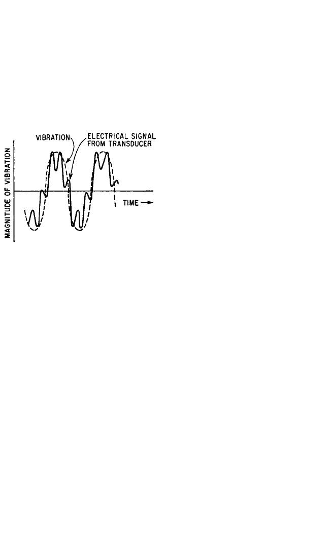
High-Frequency Limit. An acceleration transducer (accelerometer) has an upper
usable frequency limit because it responds to vibration whose frequency is less than
the natural frequency of the transducer.
The limit is a function of (1) the natural
frequency and (2) the damping of the
transducer, as discussed with reference
to Fig. 12.3. An attempt to use such a
transducer beyond this frequency limit
may result in distortion of the signal, as
illustrated in Fig. 12.15.
The upper frequency limit for slightly
damped vibration-measuring instru-
ments is important because these instru-
ments exaggerate the small amounts of
harmonic content that may be contained
in the motion, even when the operating
frequency is well within the operating
range of the instrument. The result of
exciting an undamped instrument at its
natural frequency may be to either dam-
age the instrument or obscure the de-
sired measurement. Figure 12.15 shows how a small amount of harmonic distortion
in the vibratory motion may be exaggerated by an undamped transducer.
Phase Shift. Phase shift is the time delay between the mechanical input and the
electrical output signal of the instrumentation system. Unless the phase-shift char-
acteristics of an instrumentation system meet certain requirements, a distortion may
be introduced that consists of the superposition of vibration at several different fre-
quencies. Consider first an accelerometer, for which the phase angle θ
1
is given by
Fig. 12.4. If the accelerometer is undamped, θ
1
= 0 for values of ω/ω
n
less than 1.0;
thus, the phase of the relative displacement δ is equal to that of the acceleration
being measured, for all values of frequency within the useful range of the accelerom-
eter. Therefore, an undamped accelerometer measures acceleration without distor-
tion of phase. If the fraction of critical damping ζ for the accelerometer is 0.65, the
phase angle θ
1
increases approximately linearly with the frequency ratio ω/ω
n
within
the useful frequency range of the accelerometer.Then the expression for the relative
displacement may be written
δ=δ
0
cos (ωt −θ) =δ
0
cos (ωt − aω) =δ
0
cos ω(t − a) (12.12)
where a is a constant. Thus, the relative motion δ of the instrument is displaced in
phase relative to the acceleration ü being measured; however, the increment along
the time axis is a constant independent of frequency. Consequently, the waveform of
the accelerometer output is undistorted but is delayed with respect to the waveform
of the vibration being measured. As indicated by Fig. 12.4, any value of damping in
VIBRATION TRANSDUCERS 12.13
FIGURE 12.15 Distorted response (solid line)
of a lightly damped (ζ<0.1) mass-spring ac-
celerometer to vibration (dashed line) containing
a small harmonic content of the small frequency
as the natural frequency of the accelerometer.
8434_Harris_12_b.qxd 09/20/2001 11:15 AM Page 12.13

an accelerometer other than ζ=0 or ζ=0.65 (approximately) results in a nonlinear
shift of phase with frequency and a consequent distortion of the waveform.
ENVIRONMENTAL EFFECTS
Temperature. The sensitivity, natural frequency, and damping of a transducer
may be affected by temperature.The specific effects produced depend on the type of
transducer and the details of its design.The sensitivity may increase or decrease with
temperature, or remain relatively constant. Figure 12.16 shows the variation of
damping with temperature for several different damping media. Either of two
methods may be employed to compensate for temperature effects.
1. The temperature of the pickup may be held constant by local heating or cooling.
2. The pickup characteristics may be measured as a function of temperature;if nec-
essary, the appropriate corrections can then be applied to the measured data.
Humidity. Humidity may affect the characteristics of certain types of vibration
instruments. In general, a transducer which operates at a high electrical impedance
is affected by humidity more than a transducer which operates at a low electrical
impedance. It usually is impractical to correct the measured data for humidity
effects. However, instruments that might otherwise be adversely affected by humid-
ity often are sealed hermetically to protect them from the effects of moisture.
Acoustic Noise. High-intensity sound waves often accompany high-amplitude
vibration. If the case of an accelerometer can be set into vibration by acoustic exci-
tation, error signals may result. In general, a well-designed accelerometer will not
produce a significant electrical response except at extremely high sound pressure
levels. Under such circumstances, it is likely that vibration levels also will be very
high, so that the error produced by the accelerometer’s exposure to acoustic noise
usually is not important.
12.14 CHAPTER TWELVE
FIGURE 12.16 Variation of damping with temperature for different
damping means. The ordinate indicates the fraction of critical damping ζ at
various temperatures assuming ζ=1 at 70°F (21°C).
8434_Harris_12_b.qxd 09/20/2001 11:15 AM Page 12.14