Harris C.M., Piersol A.G. Harris Shock and vibration handbook
Подождите немного. Документ загружается.


Unlike statistical reliability tests, reliability growth tests do not simulate the magni-
tudes of the service environments, although some effort is often made to simulate the
general characteristics of the environments; for example, random vibration would be
used to test equipment exposed to a random vibration service environment.
SELECTION OF SHOCK AND VIBRATION
TEST LEVELS
The test level for a shock or vibration test is the spectrum of the excitation applied to
the equipment at its mounting points by the test machine. For tests that require a
simulation of the actual service shock and vibration environments (qualification,
reliability, and some acceptance tests), the selection of test levels involves four steps,
as follows:
1. Measurement or prediction of spectra for shock and vibration environments
2. Grouping of measured or predicted spectra into appropriate zones
3. Determination of zone limits
4. Selection of specified test levels
MEASUREMENT OR PREDICTION OF SPECTRA
Where equipment is to be installed in an existing system (for example, a new alter-
nator for an existing automobile), the shock and/or vibration response of the system
structure at the mounting points of the equipment can be determined by direct
measurements (see Chap. 15). However, where equipment is to be installed in a sys-
tem that has not yet been built and/or operated, the shock and/or vibration environ-
ment at the equipment mounting points must be predicted. Procedures for the
prediction of shock and vibration environments vary widely depending upon the
characteristics of environment and the system producing it. In general, however, pre-
diction procedures can be divided into the following broad categories:
Analytical Modeling Procedures. At least crude predictions for the shock and
vibration response of a structural system at the mounting points of equipment can
be achieved using the various analytical formulations detailed in other chapters in
this handbook (for example, see Chaps. 1 through 3). The accuracy of the resulting
shock and vibration predictions depends heavily upon the complexity of the system
structure being modeled and the exact analytical modeling procedure used.
Finite Element Method (FEM) Procedures. A popular modeling procedure for
the prediction of shock and vibration environments is the finite element method
(FEM) detailed in Chap. 28, Part II. Properly characterized shock and vibration exci-
tations can be applied to an FEM model to predict the structural response at any
point of interest. The FEM model can also be used to compute the frequency
response functions between excitation and response points needed to make predic-
tions by the frequency response procedures discussed later. Depending on the com-
plexity of the structure being modeled, FEM procedures can generally produce
reasonably accurate shock and vibration predictions up to a frequency equivalent to
about the 50th normal mode of the structure.
TEST CRITERIA AND SPECIFICATIONS 20.7
8434_Harris_20_b.qxd 09/20/2001 12:12 PM Page 20.7

Statistical Energy Analysis (SEA) Procedures. At frequencies above the
range where finite element method procedures are accurate, statistical energy
analysis (SEA) procedures described in Chap. 11 are commonly used to predict
vibration environments. Specifically, as frequency increases, the response of the sys-
tem structure can be predicted in terms of the space-averaged response for each of
a set of individual structural elements that are coupled to collectively describe the
system, where each element has near-homogeneous properties and light damping;
an example is a constant thickness panel. Such prediction procedures can be
applied to a wide range of structural systems if the assumptions detailed in Chap. 11
are satisfied.
Frequency Response Procedures. For those structural systems where the shock
and/or vibration environment is due to motion excitations at one or more points (for
example, the response of an automobile to road roughness inputs at the four
wheels), responses at various points on the system structure can be predicted using
the input/output relationships detailed in Chap. 21, which involve the frequency
response function defined in Eq. (21.10). Such frequency response functions for the
system between the excitation points on the system and the mounting points of the
equipment can be estimated either by using an FEM model described in Chap. 28,
Part II, or by experimental measurements described in Chap. 21. These estimated
frequency response functions can then be used to predict the response at the equip-
ment mounting points for any arbitrary excitation spectra.
Extrapolation Procedures. The spectra of the responses measured on one sys-
tem during its operation can often be used to predict the spectra in a newer model
of the system, assuming the old and new systems have a similar purpose and are of
broadly similar design, for example, a new airplane that flies faster but otherwise is
similar in structural design to an earlier model of the airplane. In such cases, the
shock and/or vibration responses of the new system at the structural locations of
equipment can be predicted, at least coarsely, by scaling the measurements made on
the previous system based upon the differences in at least two parameters, namely,
(1) the magnitude of the original excitation to the system structure and (2) the
weight of the system structure at the points where the equipment is mounted. Specif-
ically, as a first order of approximation, the shock and/or vibration magnitude on the
new system can be assumed to vary directly with the magnitude of the excitation and
inversely with the weight of the system structure. Such extrapolation techniques
have been widely used to predict spectra for the vibration response of new aero-
space vehicles
3
and can often be applied to other types of systems as well.
GROUPING OF MEASURED OR PREDICTED SPECTRA INTO ZONES
The shock and vibration response of system structures that support equipment are
typically nonhomogeneous in space, sometimes to the extent that the spectra of the
responses vary substantially from one mounting point to another for a single item of
equipment.At relatively low frequencies, corresponding to frequencies below about
the fiftieth normal mode of the system structure (see Chap. 21), finite element
method (FEM) models for the system structure and the mounted equipment can be
used to predict the motions at the specific equipment attachment points. It is more
common, however, to define shock and vibration environments by making measure-
ments or predictions at selected points on the system structure that do not corre-
20.8 CHAPTER TWENTY
8434_Harris_20_b.qxd 09/20/2001 12:12 PM Page 20.8

spond to the exact mounting points for equipment, or if they do, the equipment is
not present during the measurements or accurately modeled for the predictions.
Hence, it is necessary to separate the measured or predicted responses at various
points on the system structure into groups, where the responses in each group have
broadly similar spectra that can be represented for test purposes by a single spec-
trum.A zone is defined as a region on the system structure that includes those points
where the measured or predicted shock and/or vibration responses have broadly
similar spectra. It is clear that a zone should correspond to a region of interest in the
formulation of shock and vibration test criteria for equipment, i.e., a single zone
should include all the attachment points for at least one item of equipment, and
preferably, for several items of equipment. However, a zone need not be a single
contiguous structural region. For example, all frames of a given size in an airplane,
no matter where they are located, might constitute a single zone if the responses of
those frames are similar.
The determination of zones is usually based upon engineering judgment and
experience. For example, given a system with frame-panel construction, engineering
judgment dictates that frames and panels should represent different zones, since the
responses of light panels will generally be greater than the much heavier frames.
Also, the responses perpendicular to the surface of the panels are generally greater
than the responses in the plane of the panels, so the responses along these two axes
might be divided into separate zones. A visual inspection of the spectra for the
measured or predicted responses also can be used to group locations with spectra of
similar magnitudes to arrive at appropriate zones. In any case, it is desirable to min-
imize the number of zones used to describe the shock and vibration responses over
those areas of the system structure where equipment will be mounted so as to mini-
mize the number of individual spectra required to test all the equipment for that
system.
DETERMINATION OF ZONE LIMITS
A zone limit (also called the maximum expected environment) is a single spectrum
that will conservatively bound the measured or predicted spectra at most or all
points within the zone, without severely exceeding the spectrum at any one point. A
zone limit may be determined using any one of several procedures.
3,7
The most com-
mon procedure is to envelop the measured or predicted spectra in the zone, but a
more rigorous approach is to compute a tolerance limit for the spectra. Specifically,
given n measurements of a random variable x, an upper tolerance limit is defined as
that value of x (denoted by L
x
) that will exceed at least β fraction of all values of x
with a confidence coefficient of γ.The fraction β represents the minimum probability
that a randomly selected value of x will be less than L
x
; the confidence coefficient γ
can be interpreted as the probability that the L
x
computed for a future set of data
will indeed exceed at least β fraction of all values of x. Tolerance limits are com-
monly expressed in terms of the ratio (100β)/(100γ). For example, a tolerance limit
determined for β=0.95 and γ=0.50 is called the 95/50 normal tolerance limit. In the
context of shock and/or vibration measurements or predictions, x represents the
spectral value at a specific frequency (see Table 20.2) for the response of the system
structure at a randomly selected point within a given zone, where x differs from
point-to-point within the zone due to the spatial variability of the response. How-
ever, x may also differ due to other factors, such as variations in the response from
one system to another of the same design or from one environmental exposure to
TEST CRITERIA AND SPECIFICATIONS 20.9
8434_Harris_20_b.qxd 09/20/2001 12:12 PM Page 20.9

another of the same system. In selecting a sample of measured or predicted spectra
to compute a tolerance limit, beyond the spectra at different locations within a zone,
it is wise to include spectra from different systems of the same design and different
environmental exposures of the same system, if feasible, so that all sources of vari-
ability are represented in the measured or predicted spectra.
Tolerance limits are most easily computed when the random variable is nor-
mally distributed (see Chap. 11). The point-to-point (spatial) variation of the shock
and vibration responses of system structures is generally not normally distributed,
but there is empirical evidence that the logarithm of the responses does have an
approximately normal distribution. Hence, by simply making the logarithmic trans-
formation
y = log
10
x (20.1)
where x is the spectral value at a specific frequency of the response within a zone, the
transformed variable y can be assumed to have a normal distribution. For n sample
values of y, a normal tolerance limit is given by
5
L
y
(n,β,γ) = y
+ ks
y
(20.2)
where y
is the sample average and s
y
is the sample standard deviation of the n trans-
formed spectral values computed as follows:
y =
n
i = 1
y
i
s
y
=
n
i = 1
(y
i
−
y)
2
(20.3)
The term k in Eq. (20.2) is called the normal tolerance factor and is a tabulated value;
a short tabulation of k for selected values of n, β, and γ, is presented in Table 20.3.
The normal tolerance limit for the transformed variable y is converted to the origi-
nal engineering units of x by
L
x
(n,β,γ) = 10
L
y
(n,β,γ)
(20.4)
To simplify test criteria, normal tolerance limits are often smoothed using a series of
straight lines, usually no more than seven with slopes of 0, ±3, or ±6 dB.
1
n − 1
1
n
20.10 CHAPTER TWENTY
TABLE 20.3 Normal Tolerance Factors for Upper Tolerance Limit
γ=0.50 γ=0.75 γ=0.90
n β=0.90 β=0.95 β=0.99 β=0.90 β=0.95 β=0.99 β=0.90 β=0.95 β=0.99
3 1.50 1.94 2.76 2.50 3.15 4.40 4.26 5.31 7.34
4 1.42 1.83 2.60 2.13 2.68 3.73 3.19 3.96 5.44
5 1.38 1.78 2.53 1.96 2.46 3.42 2.74 3.40 4.67
7 1.35 1.73 2.46 1.79 2.25 3.13 2.33 2.89 3.97
10 1.33 1.71 2.42 1.67 2.10 2.93 2.06 2.57 3.53
15 1.31 1.68 2.39 1.58 1.99 2.78 1.87 2.33 3.21
20 1.30 1.67 2.37 1.53 1.93 2.70 1.76 2.21 3.05
30 1.29 1.66 2.35 1.48 1.87 2.61 1.66 2.08 2.88
50 1.29 1.65 2.34 1.43 1.81 2.54 1.56 1.96 2.74
∞ 1.28 1.64 2.33 1.28 1.64 2.33 1.28 1.64 2.33
8434_Harris_20_b.qxd 09/20/2001 12:12 PM Page 20.10
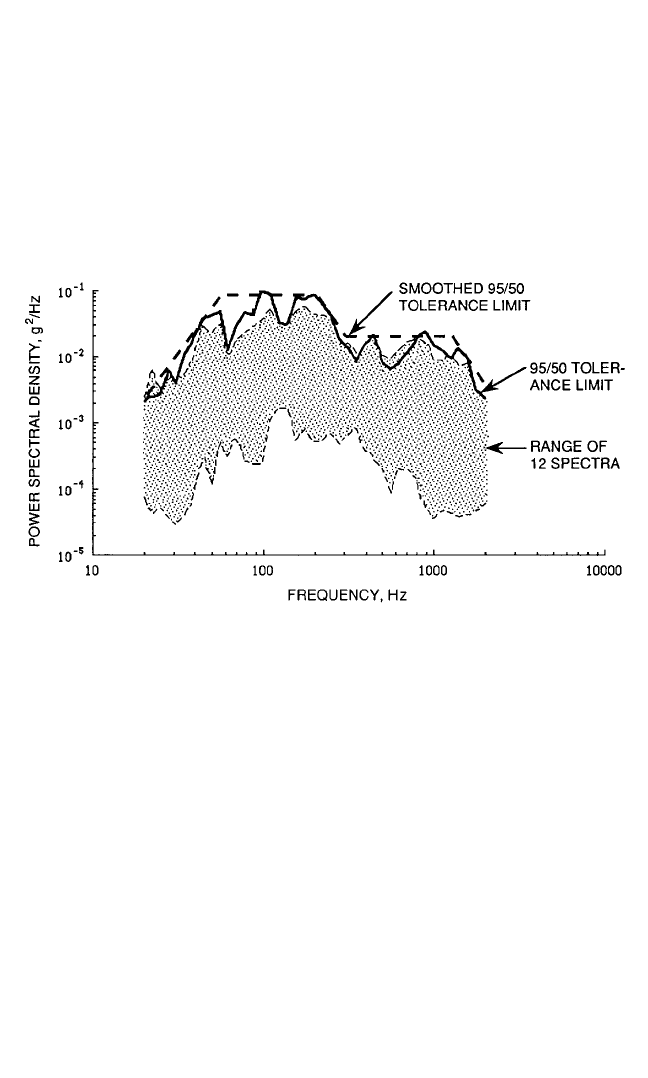
As an illustration, Fig. 20.1 shows the range of the maximax power spectra for
n = 12 vibration measurements made at different locations in a selected zone of the
structure of a large space vehicle during lift-off. Also shown in this figure are the
unsmoothed and smoothed normal tolerance limit versus frequency computed with
β=0.95 and γ=0.50 (the 95/50 limit). Note that the normal tolerance limit at most
frequencies is higher than the largest of the 12 spectral values from which the limit
is computed. However, a normal tolerance limit could be either higher or lower than
the largest spectral values from which the limit is computed, depending on the val-
ues of n, β, and γ.
TEST CRITERIA AND SPECIFICATIONS 20.11
FIGURE 20.1 95/50 normal tolerance limit for spectra of 12 vibration measurements.
SELECTION OF FINAL TEST LEVELS
A test level is the spectrum of the shock or vibration environment that is specified for
testing purposes, i.e., the spectrum given in a final test specification. The determina-
tion of a test level based upon a computed zone limit requires the selection of a
value for β, the fraction of the locations within a zone where the spectra of the shock
and/or vibration responses of the system structure will be exceeded by the zone (tol-
erance) limit. This selection is often made somewhat arbitrarily, with values in the
range 0.90 ≤β≤0.99 being the most common for acceptance and qualification tests.
However, the value of β used to arrive at a test level can be optimized based upon an
assessment of the adverse consequences (the potential cost) of an undertest versus
an overtest. Also, even with an optimum selection, modifications to the test level
may be required to account for the interactions of the equipment and the system
structure and other considerations.
Optimum Test Level Selection. A number of procedures have been developed
8
that yield an optimum test level for equipment in terms of a percentile of the envi-
ronmental distribution (which is essentially the value of β for a tolerance limit) as a
function of a “cost” ratio C
T
/C
F
, where C
T
is the cost of a test failure and C
F
is the cost
8434_Harris_20_b.qxd 09/20/2001 12:12 PM Page 20.11

of a service failure. Some of the procedures assume the equipment being tested has
already been manufactured in quantity, raising the possibility that a test failure will
lead to refurbishing costs, while others account for a safety factor in the equipment
design or a test factor based upon the assumed strength of the item being tested.The
simplest test level selection rule, which applies to the acceptance testing of a single
item of equipment, is given by
3
β= (20.5)
As an illustration, consider an item of equipment where a failure during test could
be corrected by a relatively simple replacement of an inexpensive component, but
a failure during service would be catastrophic, perhaps resulting in personal injury.
According to Eq. (20.5), the item should be tested to a very severe level relative to
the measured or predicted shock and/or vibration environment so as to sharply
minimize the risk of an undertest; for example, if a service failure is assessed to be
1000 times as costly as a test failure, β=0.999. On the other hand, consider an item
where a failure in test would lead to a difficult and expensive redesign, but a fail-
ure during service would not be catastrophic.According to Eq. (20.5), the test level
now should be moderate relative to the measured or predicted shock and/or vibra-
tion environment so as to minimize the risk of an overtest; for example, if a service
failure is assessed to be only 9 times as costly as a test failure, then β=0.90. Note
that the selection procedure does not require the determination of quantitative
costs in dollars, but only relative costs, which can be interpreted in qualitative
terms. This allows such factors as the consequences of a possible delivery delay
caused by a test failure or customer dissatisfaction caused by a service failure to
be considered. Also, the conservatism of the test level can be further increased
or decreased by selecting a larger or smaller value of γ for the tolerance limit
computation.
Equipment-Structure Interactions. Test levels are commonly specified in terms
of a motion parameter, for example, g
2
/Hz versus frequency for a random vibration
test. However, at the resonance frequencies of relatively heavy items of equipment,
the apparent mass of the equipment dramatically increases, causing the equipment
to behave like a dynamic vibration absorber on the system structure to which the
equipment is mounted (see Chap. 6). If the test machine is made to deliver the spec-
ified motion to the equipment at its resonance frequencies, a severe overtest may
occur.This problem is sometimes addressed by placing limits on the response of the
equipment or by allowing “notches” in the specified test spectrum to be introduced
at the frequencies of strong resonances of the equipment. The best approach, how-
ever, is to derive a second spectrum for the limiting force at the mounting points of
the equipment and establish criteria for a dual control test that limits both the input
force and the input motion to the equipment.
9
Added Test Level Factors. For qualification tests where the item of equipment
being tested will not be used in service, it is common to add a factor (often referred
to as a test margin) to the derived test levels to arrive at a final specified test level.
Such factors are usually justified to account for uncertainties not considered in the
determination of the test levels, such as unknown variabilities in the equipment
strength or its possible service use. These factors are sometimes selected rather
arbitrarily, with typical values ranging from 3 to 6 dB above the derived zone limits.
1
1 + (C
T
/C
F
)
20.12 CHAPTER TWENTY
8434_Harris_20_b.qxd 09/20/2001 12:12 PM Page 20.12

SELECTION OF VIBRATION TEST DURATIONS
The test duration for a vibration test is the total time the excitation is applied to the
equipment at its mounting points by the test machine. In some cases, the test dura-
tion is not relevant to the purpose of the test, for example, a development test. In
many cases, however, an appropriate simulation of the total duration of the vibration
environment anticipated in service is an important part of the test criteria. This is
particularly true of qualification and statistical reliability tests, where the purpose is
to detect design inadequacies that may lead to failures of any type during exposure
to the service vibration environment, including “wearout” failures. For shock envi-
ronments, this means exposing the equipment to repeated simulations of all the
shocks anticipated during its service life, which can usually be accomplished in a rea-
sonable period of time. For vibration environments, however, this means exposing
the equipment to a simulation of the anticipated service vibration environment for a
duration equivalent to the service life of the equipment, which may be thousands of
hours.Vibration environments usually vary widely in overall level and perhaps spec-
tral content during the equipment service life, for example, equipment on an auto-
mobile or truck in normal service use. As noted earlier in this chapter, statistical
reliability tests are sometimes performed with a duration similar to the anticipated
service life of the equipment. For qualification tests, however, it is usual to compress
a long, time-varying service environment into a stationary test level of much shorter
duration.
10
To do this, the following steps are required:
1. Assume a time-dependent failure model for the equipment
2. Compress the time-varying magnitudes of the environment into a single test level
corresponding to a conservative estimate of the maximum magnitude of the envi-
ronment
3. In some cases, increase the test level beyond the maximum magnitude of the
environment to further accelerate the test
FAILURE MODELS
A failure of an item of equipment is defined as any deterioration of performance or
any damage or malfunction that prevents the equipment from accomplishing its
intended purpose. There are two basic types of failures that may be caused by vibra-
tion:
1. Hard failure. A failure involving permanent physical damage that makes the
equipment unable to perform its intended purpose, even after the vibration is ter-
minated. Hard failures generally result in observable damage,such as the fracture
of a structural element or the permanent disability of an electronic element.
2. Soft failure. A failure involving a malfunction or deterioration of performance
during the vibration exposure that makes the equipment unable to accomplish its
intended purpose, but after the vibration is terminated, the equipment does not
reveal any damage and functions properly. Soft failures most commonly occur in
electrical, electronic, and/or optical elements, although soft failures may occa-
sionally occur in complex mechanical elements, such as gyroscopic devices.
A failure mechanism is the specific means by which an item of equipment is dam-
aged by exposure to an environment. All failure mechanisms are a function of the
TEST CRITERIA AND SPECIFICATIONS 20.13
8434_Harris_20_b.qxd 09/20/2001 12:12 PM Page 20.13

magnitude of the vibration exposure. A time-dependent failure mechanism is a func-
tion of both the magnitude and the duration of the vibration exposure. Soft failures
during exposure to a vibration environment are rarely time-dependent, i.e., they usu-
ally occur immediately at the start of the vibration exposure. On the other hand, hard
failures usually are time-dependent, although there are some exceptions. For example,
if a vibration environment produces stresses that exceed the ultimate strength of a crit-
ical element in the equipment, a fracture will occur immediately at the start of the
vibration exposure. See Chaps. 34 and 41 for further discussions of equipment failures.
To establish appropriate test durations for qualification vibration tests, only time-
dependent failure mechanisms (usually producing hard failures) are of interest.
Common examples of time-dependent failure mechanisms for equipment exposed
to vibration environments are fatigue damage, force contact wear, relative velocity
wear, and the loosening of bolts or rivets. A failure model is an analytical relation-
ship between the time-to-failure of the equipment during exposure to a vibration
environment and the magnitude of the vibration environment. For a wide class of
time-dependent failure mechanisms, the time-to-failure τ for a stationary vibration
excitation can be approximated by the inverse power law
10
given by
τ=c σ
−b
(20.6)
where σ is the stress in the equipment caused by the vibration (or any measure of the
vibration magnitude that is linearly related to stress), and b and c are constants
related to the specific failure mechanism. From Chap. 34, if the endurance limit is
ignored, the fatigue endurance curves for common metals fit the form of Eq. (20.6).
Using Eq. (20.6) and assuming a vibration test is performed that accurately sim-
ulates the basic characteristics (for example, random versus periodic) and the spec-
trum of a service vibration environment, the time required to produce a similar
amount of damage in the test environment T
t
and the time in the service environ-
ment T
e
are related by
T
t
=
b
T
e
(20.7)
where σ is the rms value of the vibration, and the subscripts t and e denote the test
and service environments, respectively. For random vibrations defined in terms of
power spectra (i.e., W(f ) defined in Chap. 22), Eq. (20.7) becomes
T
t
=
b/2
T
e
(20.8)
The value of the power b in Eqs. (20.7) and (20.8) varies widely for different failure
mechanisms. For metal fatigue damage, a value of b = 8 is reasonable for many com-
mon materials (see Fig. 34.4) and is recommended in Ref. 3. However, a value of
b = 4 is usually more appropriate for the typical failure mechanisms in electrical and
electronic equipment.
11
COMPRESSING TIME-VARYING SERVICE ENVIRONMENTS
For those vibration environments that vary substantially in severity during the equip-
ment service life, the duration of the environment can often be reduced for testing pur-
poses by using Eq. (20.7) to scale the less severe vibration levels to the most severe
levels that occur during the service life. Such scaling procedures are most applicable to
environments that vary in overall level but not substantially in spectral content. For
W
e
( f )
W
t
( f )
σ
e
σ
t
20.14 CHAPTER TWENTY
8434_Harris_20_b.qxd 09/20/2001 12:12 PM Page 20.14

example, consider an item of electrical equipment designed for a motor vehicle with a
service life of 4000 hours. Assume the anticipated service vibration environment for
the vehicle at the equipment mounting points has the rms values summarized in Table
20.4. Further assume b = 4 in Eq. (20.7), and the vibrations during the various service
conditions have a similar spectral content.Table 20.4 indicates the damage potential of
the 4000-hour service vibration environment can be simulated by a vibration test with
a duration of 80 hours at the maximum service vibration level.
For those vibration environments where the spectral content and the overall lev-
els change during service operations, the test duration computations illustrated in
Table 20.4 must be made on a frequency-by-frequency basis using Eq. (20.8) or a
similar expression for the appropriate spectral description in Table 20.2. This will
result in a different test duration at each frequency, leading to two possible testing
options: (1) a series of tests, each covering a different frequency range with a differ-
ent test duration or (2) a single test with a test duration equal to the longest test
duration computed at any frequency.The second option is usually the more practical
and assures a conservative test.
ACCELERATED TESTS
An accelerated test is a test where the test duration is reduced by increasing the test
level in a manner that will maintain the same environment-induced damage to the
equipment. The determination of a test duration for a stationary vibration test that
produces the same damage as a nonstationary vibration environment, as detailed in
the preceding section, constitutes the most desirable form of accelerated testing
because the test level never exceeds the maximum vibration level that the equip-
ment will experience during its service environment. Furthermore, most of the dam-
age experienced by equipment in service usually occurs during exposure to the
maximum vibration level in the service environment, which typically covers a small
fraction of the total service duration (see Table 20.4). In such cases, reducing the rel-
atively long durations of the less severe vibrations by scaling to the maximum level
according to Eq. (20.7) does not introduce a major error, even if the exponent in Eq.
(20.7) is inaccurate.
Highly Accelerated Tests. Situations often arise where scaling the less severe
segments of a nonstationary vibration environment to a stationary vibration level
corresponding to the maximum level of the environment may yield a test duration
that is still too long to be practical; for example, the test duration of 80 hours com-
TEST CRITERIA AND SPECIFICATIONS 20.15
TABLE 20.4 Determination of Equivalent Duration for Automobile Equipment Vibration
Environment
Duration on road rms vibration on Equivalent duration on
Type of road segment segment, hours road segment, g road segment A, hours
A. Unpaved secondary roads 40 3 40
B. Improved secondary roads 460 1.4 22
C. Primary roads 1500 0.9 12
D. Major highways 2000 0.7 6
Total equivalent duration on road segment A (hours) 80
8434_Harris_20_b.qxd 09/20/2001 12:12 PM Page 20.15

puted for the 4000-hour service environment in Table 20.4 may still be too long for
testing purposes. In such a case, it is common to further reduce the test duration by
increasing the test level beyond the maximum level the equipment will experience
during its anticipated service environment. Indeed, if no limit is placed on the rms
test level in Eq. (20.7), the test duration theoretically can be made as short as
desired, provided the ultimate strength of the equipment structure is not exceeded.
However, increasing the test level beyond the maximum level during the anticipated
service environment introduces major uncertainties in the test results, particularly if
the equipment is fabricated using different materials and/or incorporates electrical,
electronic, and/or optical elements. The problem is that the failure mechanisms of
some elements may not comply with the inverse power law in Eq. (20.6). Further-
more, even if all failure mechanisms do comply with Eq. (20.6), the exponent b may
vary from one element to another within the equipment. Hence, increasing the test
level to accelerate the test rapidly in compliance with Eq. (20.7) may cause some ele-
ments of the equipment to be undertested and others to be overtested. The result
could be the occurrence of unrepresentative failures during the accelerated test.
11
Durability and Functional Tests. A common procedure to suppress unrepresen-
tative failures that may be caused by rapidly accelerating a vibration test of equip-
ment with a long service life is to perform two separate tests, namely, a durability test
and a functional test.A durability test is intended to reveal only time-dependent fail-
ures and is rapidly accelerated to produce the same damage as the entire duration of
the service vibration environment based upon a specific damage model, for example,
Eq. (20.7). The equipment is not required to function during the durability test, and
any failures that are not time-dependent are ignored.A functional test is intended to
reveal failures that are not time-dependent (i.e., failures related only to the vibration
level) and is not accelerated with test levels that exceed the maximum expected
vibration level during the service environment. The equipment is required to func-
tion during the test, but since the failures of interest are not time-dependent, the test
duration is not critical; for example, the test duration is often fixed by the time
required to fully operate the equipment and verify that it properly performs its
intended purpose.
SHOCK AND VIBRATION TESTING
The laboratory machinery used to perform vibration tests and shock tests are
detailed in Chaps. 25 and 26, respectively. In all cases, there are several issues that
must be carefully considered in performing such tests, the most important being:
1. Identification of test failures
2. Type of excitation to be used
3. Single versus multiple-axis excitation
4. Test fixtures
IDENTIFICATION OF TEST FAILURES
In all shock and vibration tests of equipment, it is important to carefully establish
what types of equipment malfunctions or anomalies will be considered failures. This
20.16 CHAPTER TWENTY
8434_Harris_20_b.qxd 09/20/2001 12:12 PM Page 20.16