Hennessy John L., Patterson David A. Computer Architecture
Подождите немного. Документ загружается.

C-42 ■ Appendix C Review of Memory Hierarchy
The IBM 405CR embedded processor, for example, allows 1 KB, 4 KB (2
2
×
1 KB), 16 KB (2
4
× 1 KB), 64 KB (2
6
× 1 KB), 256 KB (2
8
× 1 KB), 1024 KB
(2
10
× 1 KB), and 4096 KB (2
12
× 1 KB) to act as a single page.
Four Memory Hierarchy Questions Revisited
We are now ready to answer the four memory hierarchy questions for virtual
memory.
Q1: Where Can a Block Be Placed in Main Memory?
The miss penalty for virtual memory involves access to a rotating magnetic stor-
age device and is therefore quite high. Given the choice of lower miss rates or a
simpler placement algorithm, operating systems designers normally pick lower
miss rates because of the exorbitant miss penalty. Thus, operating systems allow
blocks to be placed anywhere in main memory. According to the terminology in
Figure C.2 on page C-7, this strategy would be labeled fully associative.
Q2: How Is a Block Found If It Is in Main Memory?
Both paging and segmentation rely on a data structure that is indexed by the page
or segment number. This data structure contains the physical address of the
block. For segmentation, the offset is added to the segment’s physical address to
obtain the final physical address. For paging, the offset is simply concatenated to
this physical page address (see Figure C.22).
Page Segment
Words per address One Two (segment and offset)
Programmer visible? Invisible to application
programmer
May be visible to application
programmer
Replacing a block Trivial (all blocks are the
same size)
Hard (must find contiguous,
variable-size, unused portion of
main memory)
Memory use inefficiency Internal fragmentation
(unused portion of page)
External fragmentation (unused
pieces of main memory)
Efficient disk traffic Yes (adjust page size to
balance access time and
transfer time)
Not always (small segments may
transfer just a few bytes)
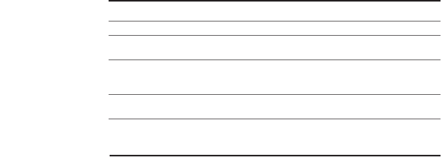
Figure C.21 Paging versus segmentation. Both can waste memory, depending on the
block size and how well the segments fit together in main memory. Programming lan-
guages with unrestricted pointers require both the segment and the address to be
passed. A hybrid approach, called paged segments, shoots for the best of both worlds:
Segments are composed of pages, so replacing a block is easy, yet a segment may be
treated as a logical unit.
C.4 Virtual Memory ■ C-43
This data structure, containing the physical page addresses, usually takes the
form of a page table. Indexed by the virtual page number, the size of the table is
the number of pages in the virtual address space. Given a 32-bit virtual address,
4 KB pages, and 4 bytes per Page Table Entry (PTE), the size of the page table
would be (2
32
/2
12
) × 2
2
= 2
22
or 4 MB.
To reduce the size of this data structure, some computers apply a hashing
function to the virtual address. The hash allows the data structure to be the length
of the number of physical pages in main memory. This number could be much
smaller than the number of virtual pages. Such a structure is called an inverted
page table. Using the previous example, a 512 MB physical memory would only
need 1 MB (8 × 512 MB/4 KB) for an inverted page table; the extra 4 bytes per
page table entry are for the virtual address. The HP/Intel IA-64 covers both bases
by offering both traditional pages tables and inverted page tables, leaving the
choice of mechanism to the operating system programmer.
To reduce address translation time, computers use a cache dedicated to these
address translations, called a translation lookaside buffer, or simply translation
buffer, described in more detail shortly.
Q3: Which Block Should Be Replaced on a Virtual Memory Miss?
As mentioned earlier, the overriding operating system guideline is minimizing
page faults. Consistent with this guideline, almost all operating systems try to
replace the least-recently used (LRU) block because if the past predicts the
future, that is the one less likely to be needed.
To help the operating system estimate LRU, many processors provide a use
bit or reference bit, which is logically set whenever a page is accessed. (To reduce
work, it is actually set only on a translation buffer miss, which is described
shortly.) The operating system periodically clears the use bits and later records
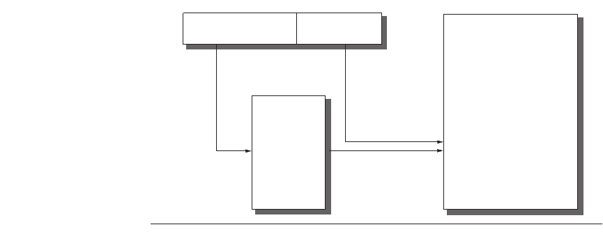
Figure C.22 The mapping of a virtual address to a physical address via a page table.
Main
memory
Page
table
Virtual address
Virtual page number
Page offset
Physical address
C-44 ■ Appendix C Review of Memory Hierarchy
them so it can determine which pages were touched during a particular time
period. By keeping track in this way, the operating system can select a page that
is among the least-recently referenced.
Q4: What Happens on a Write?
The level below main memory contains rotating magnetic disks that take millions
of clock cycles to access. Because of the great discrepancy in access time, no one
has yet built a virtual memory operating system that writes through main memory
to disk on every store by the processor. (This remark should not be interpreted as
an opportunity to become famous by being the first to build one!) Thus, the write
strategy is always write back.
Since the cost of an unnecessary access to the next-lower level is so high, vir-
tual memory systems usually include a dirty bit. It allows blocks to be written to
disk only if they have been altered since being read from the disk.
Techniques for Fast Address Translation
Page tables are usually so large that they are stored in main memory and are
sometimes paged themselves. Paging means that every memory access logically
takes at least twice as long, with one memory access to obtain the physical
address and a second access to get the data. As mentioned in Chapter 5, we use
locality to avoid the extra memory access. By keeping address translations in a
special cache, a memory access rarely requires a second access to translate the
data. This special address translation cache is referred to as a translation looka-
side buffer (TLB), also called a translation buffer (TB).
A TLB entry is like a cache entry where the tag holds portions of the virtual
address and the data portion holds a physical page frame number, protection
field, valid bit, and usually a use bit and dirty bit. To change the physical page
frame number or protection of an entry in the page table, the operating system
must make sure the old entry is not in the TLB; otherwise, the system won’t
behave properly. Note that this dirty bit means the corresponding page is dirty,
not that the address translation in the TLB is dirty nor that a particular block in
the data cache is dirty. The operating system resets these bits by changing the
value in the page table and then invalidates the corresponding TLB entry. When
the entry is reloaded from the page table, the TLB gets an accurate copy of the
bits.
Figure C.23 shows the Opteron data TLB organization, with each step of the
translation labeled. This TLB uses fully associative placement; thus, the transla-
tion begins (steps 1 and 2) by sending the virtual address to all tags. Of course,
the tag must be marked valid to allow a match. At the same time, the type of
memory access is checked for a violation (also in step 2) against protection infor-
mation in the TLB.
For reasons similar to those in the cache case, there is no need to include the
12 bits of the page offset in the TLB. The matching tag sends the corresponding
C.4 Virtual Memory ■ C-45
physical address through effectively a 40:1 multiplexor (step 3). The page offset
is then combined with the physical page frame to form a full physical address
(step 4). The address size is 40 bits.
Address translation can easily be on the critical path determining the clock
cycle of the processor, so the Opteron uses virtually addressed, physically tagged
L1 caches.
Selecting a Page Size
The most obvious architectural parameter is the page size. Choosing the page is a
question of balancing forces that favor a larger page size versus those favoring a
smaller size. The following favor a larger size:
■ The size of the page table is inversely proportional to the page size; memory
(or other resources used for the memory map) can therefore be saved by mak-
ing the pages bigger.
■ As mentioned in Section C.3, a larger page size can allow larger caches with
fast cache hit times.
■ Transferring larger pages to or from secondary storage, possibly over a net-
work, is more efficient than transferring smaller pages.
■ The number of TLB entries is restricted, so a larger page size means that
more memory can be mapped efficiently, thereby reducing the number of
TLB misses.
It is for this final reason that recent microprocessors have decided to support mul-
tiple page sizes; for some programs, TLB misses can be as significant on CPI as
the cache misses.
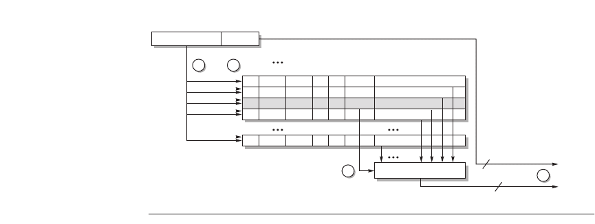
Figure C.23 Operation of the Opteron data TLB during address translation. The four
steps of a TLB hit are shown as circled numbers. This TLB has 40 entries. Section C.5
describes the various protection and access fields of an Opteron page table entry.
<28>
Virtual page
number
<36>
Page
offset
<12>
<1>
V
<1>
D
<1>
A
<36>
Tag
<28>
Physical address
(Low-order 12 bits
of address)
(High-order 28 bits of address)
40-bit
physical
address
R/W U/S
40:1 mux
21
4
<12>
3
C-46 ■ Appendix C Review of Memory Hierarchy
The main motivation for a smaller page size is conserving storage. A small
page size will result in less wasted storage when a contiguous region of virtual
memory is not equal in size to a multiple of the page size. The term for this
unused memory in a page is internal fragmentation. Assuming that each process
has three primary segments (text, heap, and stack), the average wasted storage
per process will be 1.5 times the page size. This amount is negligible for comput-
ers with hundreds of megabytes of memory and page sizes of 4 KB to 8 KB. Of
course, when the page sizes become very large (more than 32 KB), storage (both
main and secondary) could be wasted, as well as I/O bandwidth. A final concern
is process start-up time; many processes are small, so a large page size would
lengthen the time to invoke a process.
Summary of Virtual Memory and Caches
With virtual memory, TLBs, first-level caches, and second-level caches all map-
ping portions of the virtual and physical address space, it can get confusing what
bits go where. Figure C.24 gives a hypothetical example going from a 64-bit vir-
tual address to a 41-bit physical address with two levels of cache. This L1 cache
is virtually indexed, physically tagged since both the cache size and the page size
are 8 KB. The L2 cache is 4 MB. The block size for both is 64 bytes.
First, the 64-bit virtual address is logically divided into a virtual page number
and page offset. The former is sent to the TLB to be translated into a physical
address, and the high bit of the latter is sent to the L1 cache to act as an index. If
the TLB match is a hit, then the physical page number is sent to the L1 cache tag
to check for a match. If it matches, it’s an L1 cache hit. The block offset then
selects the word for the processor.
If the L1 cache check results in a miss, the physical address is then used to try
the L2 cache. The middle portion of the physical address is used as an index to
the 4 MB L2 cache. The resulting L2 cache tag is compared to the upper part of
the physical address to check for a match. If it matches, we have an L2 cache hit,
and the data are sent to the processor, which uses the block offset to select the
desired word. On an L2 miss, the physical address is then used to get the block
from memory.
Although this is a simple example, the major difference between this drawing
and a real cache is replication. First, there is only one L1 cache. When there are
two L1 caches, the top half of the diagram is duplicated. Note this would lead to
two TLBs, which is typical. Hence, one cache and TLB is for instructions, driven
from the PC, and one cache and TLB is for data, driven from the effective
address.
The second simplification is that all the caches and TLBs are direct mapped.
If any were n-way set associative, then we would replicate each set of tag mem-
ory, comparators, and data memory n times and connect data memories with an
n:1 multiplexor to select a hit. Of course, if the total cache size remained the
same, the cache index would also shrink by log2n bits according to the formula in
Figure C.7 on page C-21.
C.5 Protection and Examples of Virtual Memory ■ C-47
The invention of multiprogramming, where a computer would be shared by
several programs running concurrently, led to new demands for protection and
sharing among programs. These demands are closely tied to virtual memory in
computers today, and so we cover the topic here along with two examples of vir-
tual memory.
Multiprogramming leads to the concept of a process. Metaphorically, a pro-
cess is a program’s breathing air and living space—that is, a running program
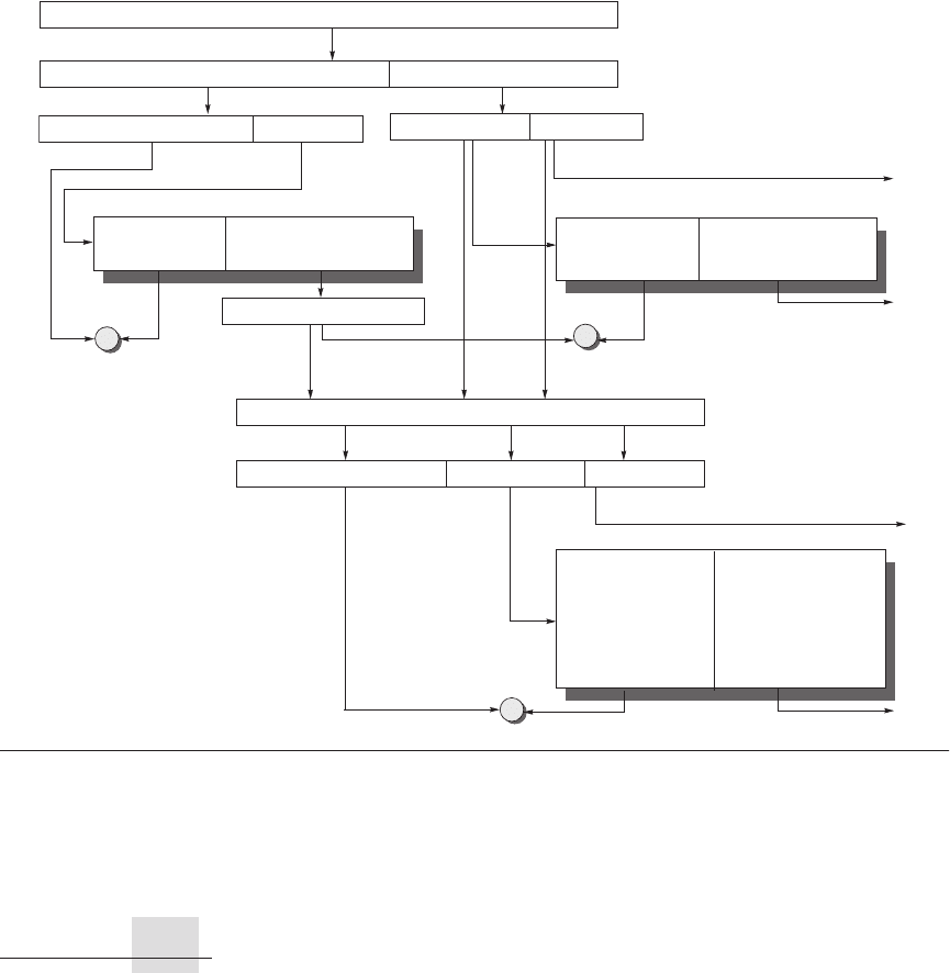
Figure C.24 The overall picture of a hypothetical memory hierarchy going from virtual address to L2 cache
access. The page size is 8 KB. The TLB is direct mapped with 256 entries. The L1 cache is a direct-mapped 8 KB, and
the L2 cache is a direct-mapped 4 MB. Both use 64-byte blocks. The virtual address is 64 bits and the physical address
is 41 bits. The primary difference between this simple figure and a real cache is replication of pieces of this figure.
Virtual address <64>
Physical address <41>
Virtual page number <51>
L1 tag compare address <28>
L2 tag compare address <19>
L2 cache index <16> Block offset <6>
Page offset <13>
L1 cache tag <43>
L1 data <512>
TLB tag <43>
TLB data <28>
L1 cache index <7> Block offset <6>TLB tag compare address <43> TLB index <8>
L2 cache tag <19>
L2 data <512>
=?
=?
=?
To CPU
To CPU
To CPU
To L1 cache or CPU
C.5 Protection and Examples of Virtual Memory
C-48 ■ Appendix C Review of Memory Hierarchy
plus any state needed to continue running it. Time-sharing is a variation of multi-
programming that shares the processor and memory with several interactive users
at the same time, giving the illusion that all users have their own computers.
Thus, at any instant it must be possible to switch from one process to another.
This exchange is called a process switch or context switch.
A process must operate correctly whether it executes continuously from start
to finish, or it is interrupted repeatedly and switched with other processes. The
responsibility for maintaining correct process behavior is shared by designers of
the computer and the operating system. The computer designer must ensure that
the processor portion of the process state can be saved and restored. The operat-
ing system designer must guarantee that processes do not interfere with each oth-
ers’ computations.
The safest way to protect the state of one process from another would be to
copy the current information to disk. However, a process switch would then take
seconds—far too long for a time-sharing environment.
This problem is solved by operating systems partitioning main memory so
that several different processes have their state in memory at the same time. This
division means that the operating system designer needs help from the computer
designer to provide protection so that one process cannot modify another.
Besides protection, the computers also provide for sharing of code and data
between processes, to allow communication between processes or to save mem-
ory by reducing the number of copies of identical information.
Protecting Processes
Processes can be protected from one another by having their own page tables,
each pointing to distinct pages of memory. Obviously, user programs must be
prevented from modifying their page tables or protection would be circumvented.
Protection can be escalated, depending on the apprehension of the computer
designer or the purchaser. Rings added to the processor protection structure
expand memory access protection from two levels (user and kernel) to many
more. Like a military classification system of top secret, secret, confidential, and
unclassified, concentric rings of security levels allow the most trusted to access
anything, the second most trusted to access everything except the innermost
level, and so on. The “civilian” programs are the least trusted and, hence, have
the most limited range of accesses. There may also be restrictions on what pieces
of memory can contain code—execute protection—and even on the entrance
point between the levels. The Intel 80x86 protection structure, which uses rings,
is described later in this section. It is not clear whether rings are an improvement
in practice over the simple system of user and kernel modes.
As the designer’s apprehension escalates to trepidation, these simple rings
may not suffice. Restricting the freedom given a program in the inner sanctum
requires a new classification system. Instead of a military model, the analogy of
this system is to keys and locks: A program can’t unlock access to the data unless
it has the key. For these keys, or capabilities, to be useful, the hardware and oper-
C.5 Protection and Examples of Virtual Memory ■ C-49
ating system must be able to explicitly pass them from one program to another
without allowing a program itself to forge them. Such checking requires a great
deal of hardware support if time for checking keys is to be kept low.
The 80x86 architecture has tried several of these alternatives over the years.
Since backwards compatibility is one of the guidelines of this architecture, the
most recent versions of the architecture include all of its experiments in virtual
memory. We’ll go over two of the options here: first, the older segmented address
space and then the newer flat, 64-bit address space.
A Segmented Virtual Memory Example:
Protection in the Intel Pentium
The second system is the most dangerous system a man ever designs. . . . The
general tendency is to over-design the second system, using all the ideas and frills
that were cautiously sidetracked on the first one.
F. P. Brooks, Jr.
The Mythical Man-Month (1975)
The original 8086 used segments for addressing, yet it provided nothing for vir-
tual memory or for protection. Segments had base registers but no bound regis-
ters and no access checks, and before a segment register could be loaded the
corresponding segment had to be in physical memory. Intel’s dedication to virtual
memory and protection is evident in the successors to the 8086, with a few fields
extended to support larger addresses. This protection scheme is elaborate, with
many details carefully designed to try to avoid security loopholes. We’ll refer to it
as IA-32. The next few pages highlight a few of the Intel safeguards; if you find
the reading difficult, imagine the difficulty of implementing them!
The first enhancement is to double the traditional two-level protection model:
the IA-32 has four levels of protection. The innermost level (0) corresponds to the
traditional kernel mode, and the outermost level (3) is the least privileged mode.
The IA-32 has separate stacks for each level to avoid security breaches between
the levels. There are also data structures analogous to traditional page tables that
contain the physical addresses for segments, as well as a list of checks to be made
on translated addresses.
The Intel designers did not stop there. The IA-32 divides the address space,
allowing both the operating system and the user access to the full space. The IA-
32 user can call an operating system routine in this space and even pass
parameters to it while retaining full protection. This safe call is not a trivial
action, since the stack for the operating system is different from the user’s stack.
Moreover, the IA-32 allows the operating system to maintain the protection level
of the called routine for the parameters that are passed to it. This potential loop-
hole in protection is prevented by not allowing the user process to ask the operat-
ing system to access something indirectly that it would not have been able to
access itself. (Such security loopholes are called Trojan horses.)
C-50 ■ Appendix C Review of Memory Hierarchy
The Intel designers were guided by the principle of trusting the operating sys-
tem as little as possible, while supporting sharing and protection. As an example of
the use of such protected sharing, suppose a payroll program writes checks and also
updates the year-to-date information on total salary and benefits payments. Thus,
we want to give the program the ability to read the salary and year-to-date informa-
tion, and modify the year-to-date information but not the salary. We will see the
mechanism to support such features shortly. In the rest of this subsection, we will
look at the big picture of the IA-32 protection and examine its motivation.
Adding Bounds Checking and Memory Mapping
The first step in enhancing the Intel processor was getting the segmented address-
ing to check bounds as well as supply a base. Rather than a base address, the seg-
ment registers in the IA-32 contain an index to a virtual memory data structure
called a descriptor table. Descriptor tables play the role of traditional page tables.
On the IA-32 the equivalent of a page table entry is a segment descriptor. It con-
tains fields found in PTEs:
■ Present bit—Equivalent to the PTE valid bit, used to indicate this is a valid
translation
■ Base field—Equivalent to a page frame address, containing the physical
address of the first byte of the segment
■ Access bit—Like the reference bit or use bit in some architectures that is
helpful for replacement algorithms
■ Attributes field—Specifies the valid operations and protection levels for
operations that use this segment
There is also a limit field, not found in paged systems, which establishes the
upper bound of valid offsets for this segment. Figure C.25 shows examples of IA-
32 segment descriptors.
IA-32 provides an optional paging system in addition to this segmented
addressing. The upper portion of the 32-bit address selects the segment
descriptor, and the middle portion is an index into the page table selected by the
descriptor. We describe below the protection system that does not rely on paging.
Adding Sharing and Protection
To provide for protected sharing, half of the address space is shared by all pro-
cesses and half is unique to each process, called global address space and local
address space, respectively. Each half is given a descriptor table with the appro-
priate name. A descriptor pointing to a shared segment is placed in the global
descriptor table, while a descriptor for a private segment is placed in the local
descriptor table.
A program loads an IA-32 segment register with an index to the table and a
bit saying which table it desires. The operation is checked according to the
C.5 Protection and Examples of Virtual Memory ■ C-51
attributes in the descriptor, the physical address being formed by adding the off-
set in the processor to the base in the descriptor, provided the offset is less than
the limit field. Every segment descriptor has a separate 2-bit field to give the legal
access level of this segment. A violation occurs only if the program tries to use a
segment with a lower protection level in the segment descriptor.
We can now show how to invoke the payroll program mentioned above to
update the year-to-date information without allowing it to update salaries. The
program could be given a descriptor to the information that has the writable field
clear, meaning it can read but not write the data. A trusted program can then be
supplied that will only write the year-to-date information. It is given a descriptor
with the writable field set (Figure C.25). The payroll program invokes the trusted
code using a code segment descriptor with the conforming field set. This setting
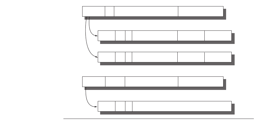
Figure C.25 The IA-32 segment descriptors are distinguished by bits in the
attributes field. Base, limit, present, readable, and writable are all self-explanatory. D
gives the default addressing size of the instructions: 16 bits or 32 bits. G gives the gran-
ularity of the segment limit: 0 means in bytes and 1 means in 4 KB pages. G is set to 1
when paging is turned on to set the size of the page tables. DPL means descriptor privi-
lege level—this is checked against the code privilege level to see if the access will be
allowed. Conforming says the code takes on the privilege level of the code being called
rather than the privilege level of the caller; it is used for library routines. The expand-
down field flips the check to let the base field be the high-water mark and the limit field
be the low-water mark. As you might expect, this is used for stack segments that grow
down. Word count controls the number of words copied from the current stack to the
new stack on a call gate. The other two fields of the call gate descriptor, destination
selector and destination offset, select the descriptor of the destination of the call and the
offset into it, respectively. There are many more than these three segment descriptors
in the IA-32 protection model.
Attributes Base Limit
8 bits 4 bits 32 bits
24 bits
Present
Code segment
DPL 11 Conforming Readable Accessed
Present
Data segment
DPL 10 Expand down Writable Accessed
Attributes Destination selector Destination offset
8 bits 16 bits
16 bits
Word
count
8 bits
Present
Call gate
DPL
0 00100
GD