Kuppan T. Heat Exchanger Design Handbook
Подождите немного. Документ загружается.


-----
44
Chapter
2
!
I
11
'I'
#
t
/
'$0
'$580
R>1
R>1
Tt
(a)
(b)
Figure
5
Temperature distribution in
a
E,
exchanger. (a) Without temperature cross;
(b)
with temperature
cross
[I].
Heat Exchanger Therrnohydraulic Fundamentals
45
6.
THERMAL RELATION FORMULAS FOR VARIOUS FLOW
ARRANGEMENTS AND PASS ARRANGEMENTS
The heat exchanger effectiveness is defined as the ratio of the overall temperature drop of the
weaker stream to the maximum possible temperature difference between the fluid inlet tempera-
tures, The following assumptions are commonly made
in
deriving thermal effectiveness.
1.
The overall heat-transfer coefficient is constant throughout the exchanger.
2.
Each pass has the same heat-transfer area; that is, unsymmetrical pass arrangements are
not considered.
3.
There is no phase change.
4.
The specific heat of each fluid is constant and independent of temperature.
5.
The flow rates of both streams are steady.
6.
The flow of both fluids is evenly distributed over both the local and the total transfer area.
7.
Heat losses from the system are negligible.
In
this section, thermal relation formulas for
(1)
various flow arrangements-parallel flow,
counterflow, and crossflow,
(2)
various types of heat exchangers-compact and shell and tube,
and
(3)
multipass arrangements or multiple units of both compact and shell and tube heat
exchangers are presented. Most of the formulas are tabulated and the thermal effectiveness
charts are given. Mostly counterflow arrangements are considered. For shell and tube ex-
changers, formulas are given for both parallel flow and counterflow, but thermal effectiveness
charts are given only for counterflow arrangements referred to tube side (similar to TEMA
Standards). Thermal effectiveness relations referred to the shell side can be derived from the
“flow reversibility” principle. Wherever thermal effectiveness relations are not given for paral-
lel flow arrangements can be easily derived (wherever applicable) from the “flow reversibility”
principle. Customarily, the E-NTU method is employed for compact heat exchangers. In this
method, the capacity ratio
C*
is always
Il.
Hence, thermal effectiveness charts are given
in
terms of E-C*-NTU, and wherever possible, the thermal effectiveness charts are given
in
terms
of P-R-F-NTU, instead of &-C*-NTU.
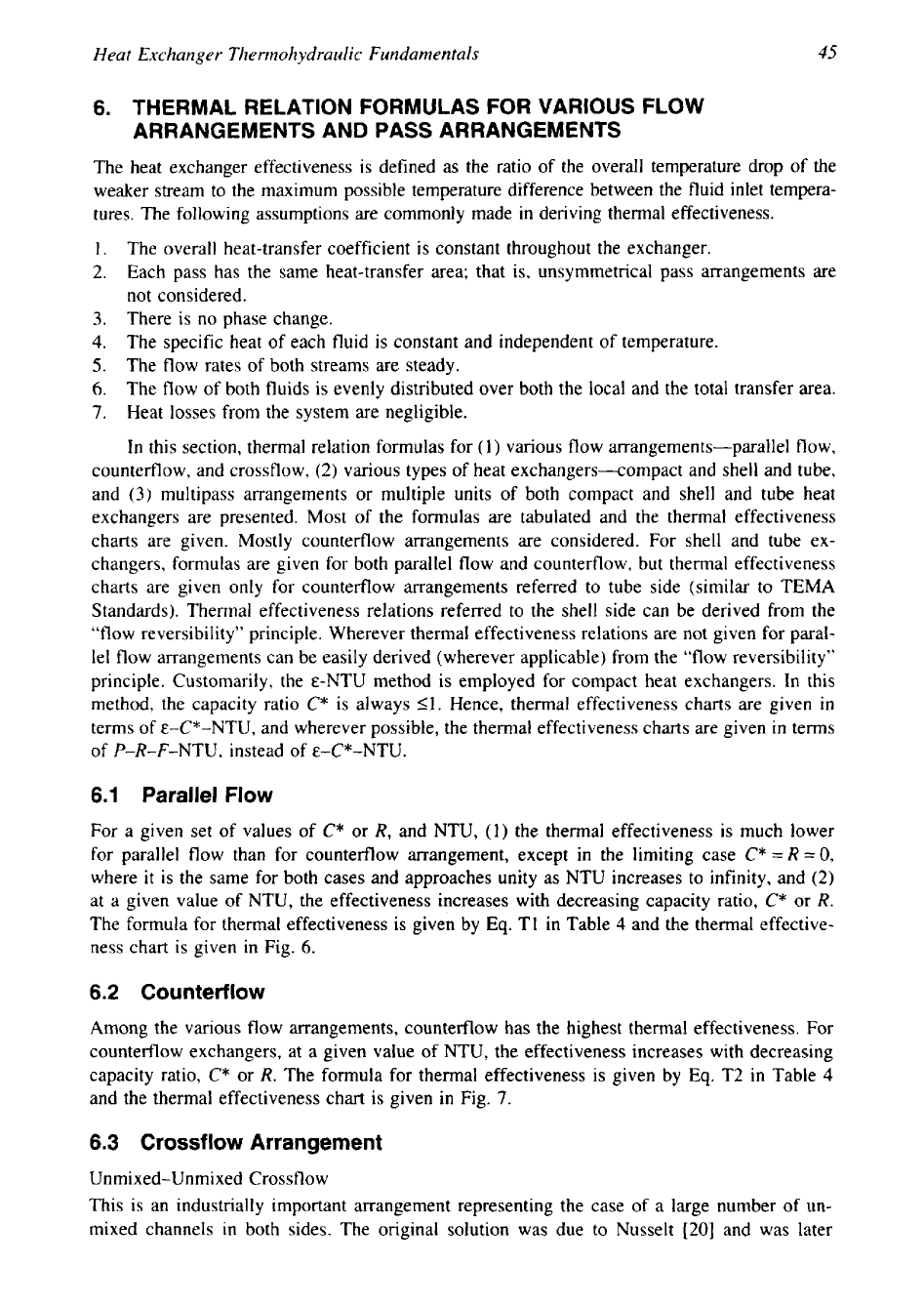
6.1
Parallel
Flow
For a given set of values of
C*
or
R,
and NTU,
(1)
the thermal effectiveness
is
much lower
for parallel flow than for counterflow arrangement, except in the limiting case
C*
=R
=0,
where
it
is the same for both cases and approaches unity as NTU increases to infinity, and (2)
at a given value of NTU, the effectiveness increases with decreasing capacity ratio,
C*
or
R.
The formula for thermal effectiveness is given by
Eq.
T1 in Table
4
and the thermal effective-
ness chart is given in Fig.
6.
6.2
Counterflow
Among the various flow arrangements, counterflow has the highest thermal effectiveness. For
counterflow exchangers, at a given value of
NTU,
the effectiveness increases with decreasing
capacity ratio,
C*
or
R.
The formula for thermal effectiveness
is
given by
Eq.
T2 in Table
4
and the thermal effectiveness chart is given
in
Fig.
7.
6.3
Crossflow Arrangement
Unmixed-Unmixed Crossflow
This is an industrially important arrangement representing the case of a large number of
un-
mixed channels in both sides. The original solution was due to Nusselt [20] and was later

46
Chapter
2
Table
4
Thermal Effectiveness Relations for Basic Cases
Q.
no./
Flow arrangement Ref. General formula Value for R
=
1
and special cases
T1
1
-
-NTCI
l+Rl
p
=
'r
1
-
[-?NTCi
]
forR=
I
P=
l+R
2
=
1
-
-WO
for
R=O
Parallel flow;
E,,,
=
50%
for R
=
1
stream symmetric.
2
s-'
Countefflow;
stream symmetric
For R
=
1,
this equation holds.
2
Cross flow;
Both
the fluids unmixed;
For
C*
=
1
stream symmetric.
E
=
1
-
-2NTCl
[I(,
(2
NTU)
+
11
(2
NTU)]
Crossflow; one fluid mixed
Weaker/C,,,,, fluid mixed
and the other fluid
unmixed:
(
1
)
weaker/C,,,,,
PI
=
[
1
-
exp(-WR)]
fluid unmixed; (2) stronger/
K
=
1
-
exp(-RNTU)
C,,,
fluid unmixed
+
t-+
T6
Stronger/C,,, fluid mixed
2
2
P,
=
[
1
-
exp(-KR)]
p,
=
1
-
p
VII
,
c
T7
R
K
=
1
-
exp(-NTU)
1
1
P=
p=-
2 1
(;+;-A]
K,-NTU
T8
2
Crossflow; mixed-mixed
flow; stream symmetric
same as
J,--
47
Heat Exchanger The
rino
hydra
u
1
ic
Fun
damn ta
Is
1.0
0.9
0.8
0.7
0.6
0.5
0.4
0.3
0.2
0.1
0.0
(a)
NTU
Figure
6
(a) Parallel
flow;
stream symmetric, R-P-NTU chart.
reformulated into a more manageable equation by Mason [21]. Mason’s formula is given by
Eq.
T3 in Table 4, and this equation can be used for P-NTU-R relation. Baclic [22] presents
Nusselt’s equation
in
terms of
a
modified Bessel function of the first kind as given
in
Eq.
T4
in
Table 4; Eckert
(231
provide a simplified formula without involving Bessel function as given
by Eq. T5 in Table 4, and this equation predicts
E
within
+1%
of
E
from
Eq.
T4
of Table
4
for
1
<
NTU
<
7;
Eqs. T4 and T5 can be used for formulas involving
C*
I
1
only.
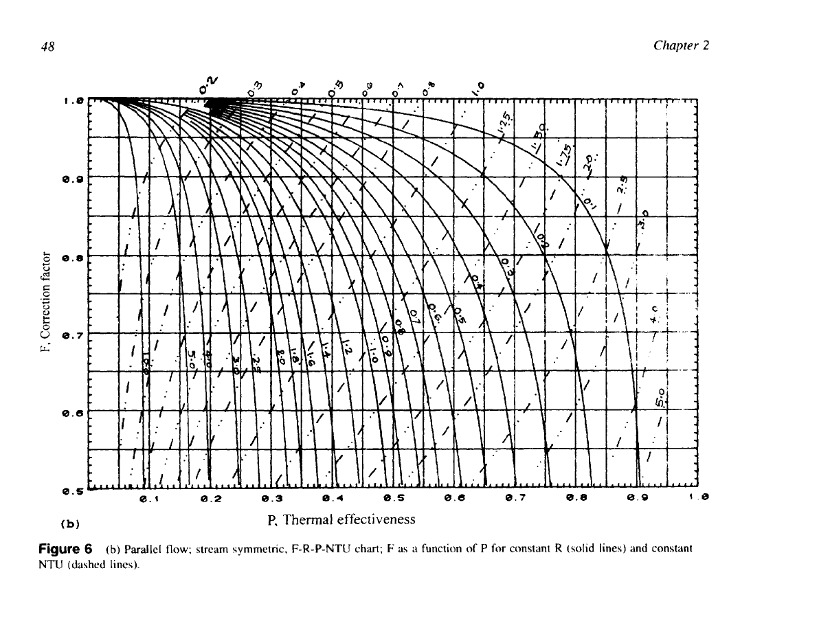
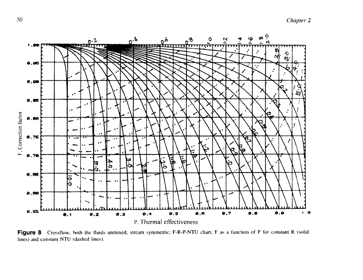
The thermal effectiveness chart as per
Eq.
T3
is given in Fig.
8
and as per
Eq.
T4
is
given
in
Fig.
9.
Unmixed-Mixed Crossflow
In this arrangement, one fluid is mixed and the other
is
unmixed.
A
typical example
is
a bare
tube compact heat exchanger
in
which the fluid outside the tube is mixed, whereas the tube-
side fluid is unmixed. There are two possible cases:
(1)
weaker fluid
(C,,,,,,)
is mixed, and
(2)
stronger fluid
(C,,,,,)
is
mixed. Formulas for thermal effectiveness for the weaker fluid mixed
are given by
Eq.
T6
and for the stronger fluid mixed by
Eq.
T7
in
Table
4.
The thermal
48
Chapter
2
I
.e
0.0
0.8
U
0.7
0.6
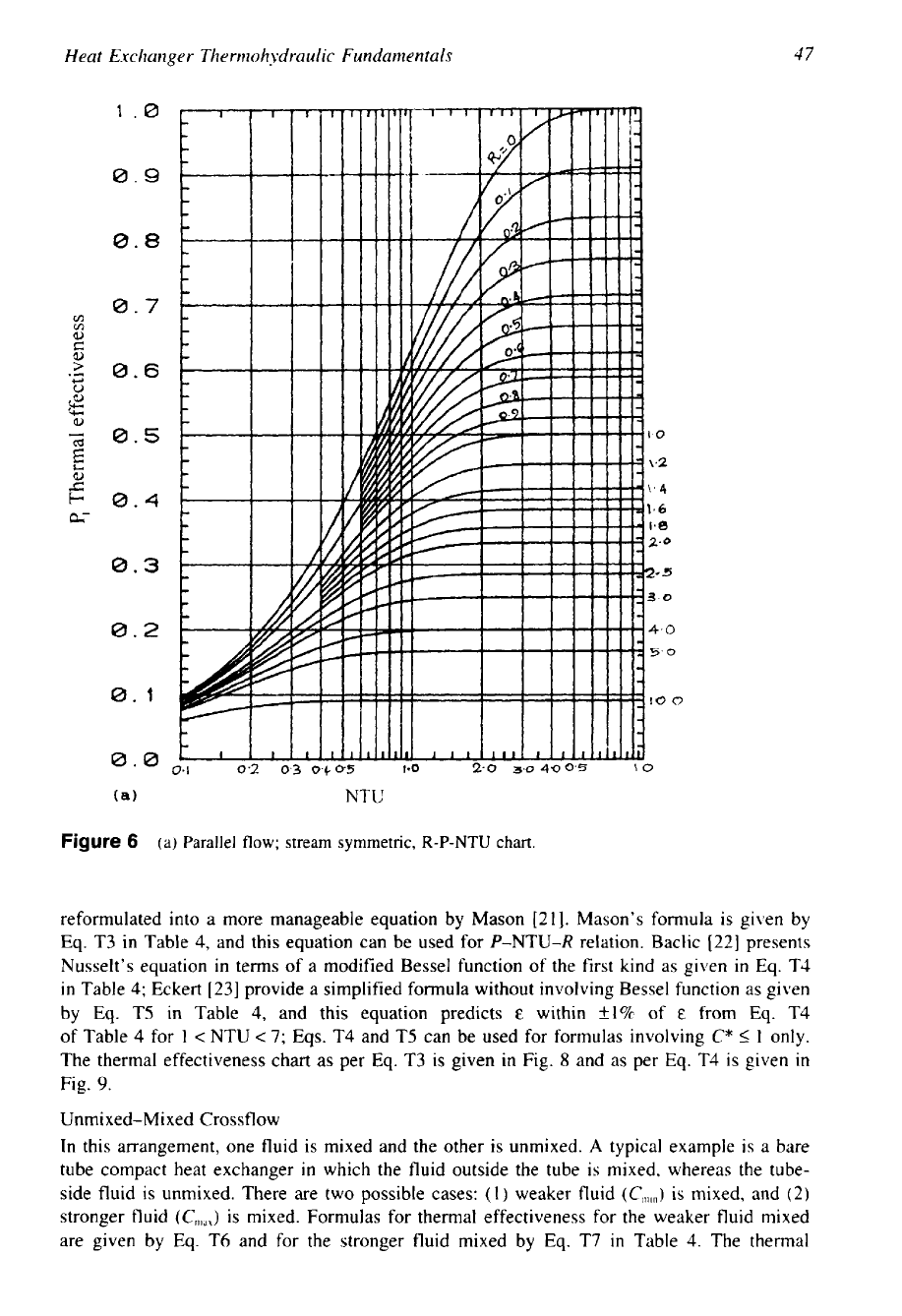
Figure
6
(b)
Parallel
flow;
stream symmetric,
F-R-P-NTU
chart;
F
as
a function
of
P
for
constant
R
(solid lines) and constant
NTU
(dashed lines).

49
Heat Exchanger Thermohydraulic Fundamentals
1.0
0.9
0.8
0.7
0.6
0.5
0.4
&-
0.3
0.2
0.1
0.0,
NTU
Figure
7
Counterflow;
stream
symmetric, R-P-NTU
chart.
effectiveness charts are given in Fig.
10
for the weaker fluid mixed and Fig.
11
for the stronger
fluid mixed. For
R
=
1
or
C*
=
1,
the thermal effectiveness is the same for both cases.
Mixed-Mixed Crossflow
This case has no industrial application and is shown here only as an extreme of the crossflow
arrangement. The solution is identical to the
TEMA
J
shell with infinite tube-side passes. The
formula for thermal effectiveness is given by
Eq.
T8 in Table
4.
Single or Multiple Rows in Crossflow
Many process heat exchangers provide a crossflow arrangement between the hot (or cold)
process fluid that flows through the tubes and the external coolant (or hot air such as super-
charged engine intake air), usually air. Because this flow arrangement is not strictly countercur-
rent, the MTD must be corrected by applying a correction factor,
F.
The factor
F
depends on
the terminal temperatures, the number of tube rows per pass, and the number of passes. The
basic unmixed-unmixed case, shown in Fig.
12,
assumes a large number of flow channels in
50
Chapter
2
1.88
O.S
0.-
0.-
c
0
0.76
ii
0.70
0.-
0.65
P.
Thermal
effectiveness
Figure
8
Crossflow;
both the fluids unmixed; stream symmetric; F-R-P-NTU chart; F as a function
of
P
for constant
R
(solid
lines) and constant NTU (dashed lines).
Heat Exchanger Thennohydraulic Fundamentals
51
1.8
0.9
0.8
0.7
0.6
vl
b)
0.5
>
c,
0
;E
%
0.4
c
8
0.3
&=
4
0.2
5
10
0.1
0.0
0
NTU
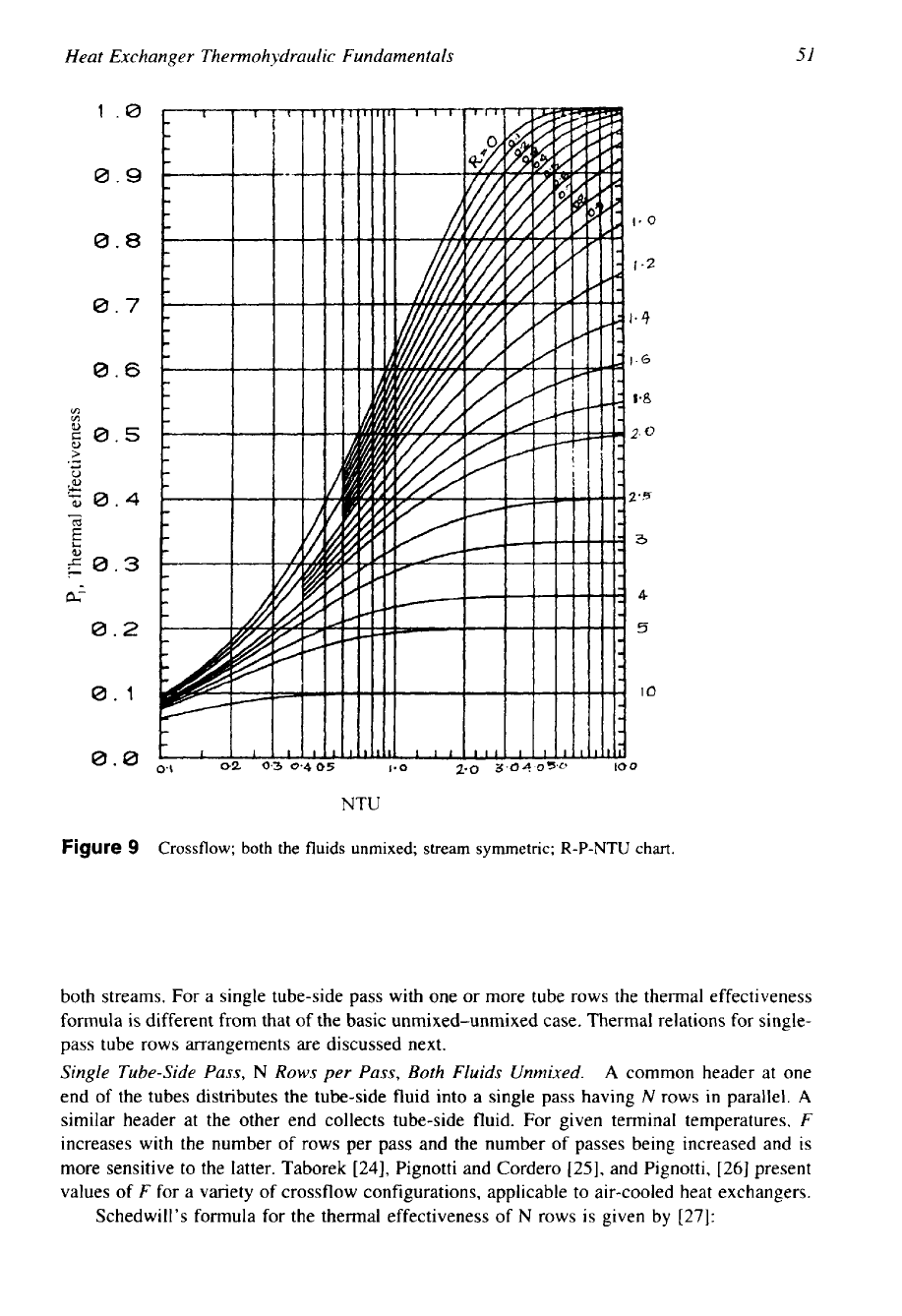
Figure
9
Crossflow;
both
the
fluids
unmixed; stream symmetric;
R-P-NTU
chart.
both streams. For a single tube-side pass with one or more tube rows the thermal effectiveness
formula
is
different from that of the basic unmixed-unmixed case. Thermal relations for single-
pass tube rows arrangements are discussed next.
Single Tube-Side Pass,
N
Rows
per
Pass, Both Fluids Unmixed.
A
common header at one
end of the tubes distributes the tube-side fluid into a single pass having
N
rows in parallel.
A
similar header at the other end collects tube-side fluid. For given terminal temperatures,
F
increases with the number of rows per pass and the number of passes being increased and is
more sensitive to the latter. Taborek
[24],
Pignotti and Cordero
[25],
and Pignotti,
[26]
present
values of
F
for a variety of crossflow configurations, applicable to air-cooled heat exchangers.
Schedwill’s formula for the thermal effectiveness of
N
rows is given by
[27]:
52
Chapter
2
1.0
0.9
0.8
0.7
0.6
0.5
0.4
0.3
0.2
0.1
0.0
NTU
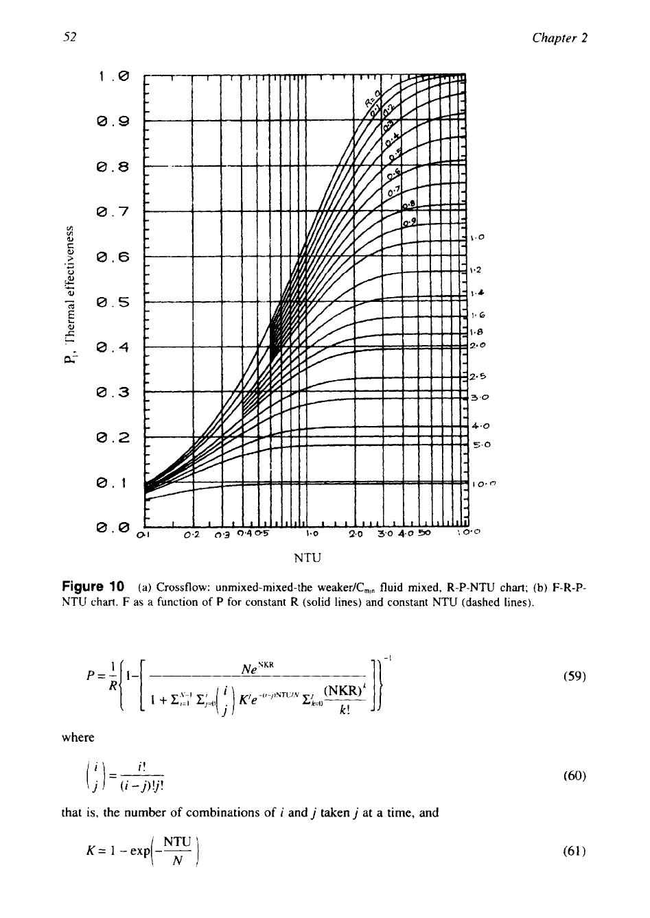
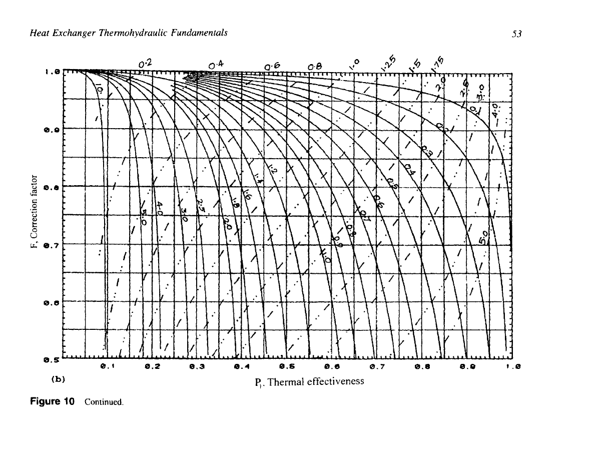
Figure
10
(a) Crossflow: unmixed-mixed-the weaker/C,,, fluid mixed, R-P-NTU chart;
(b)
F-R-P-
NTU
chart.
F
as a function of
P
for constant R (solid lines) and constant
NTU
(dashed lines).
1
Ne
NKR
11
-I
(59)
p=-
1-
R
where
i!
(;)=m
that
is,
the number
of
combinations
of
i
and
j
taken
j
at a time, and
Heat Exchanger Thermohydraulic Fundamentals
53
1
.e
8.9
0.s
(b
'1
c,
Thermal
effectiveness
Figure
10
Continued.