Lowenthal G., Airey P. Practical Applications of Radioactivity and Nuclear Radiations
Подождите немного. Документ загружается.

powerful approach for investigating sub-optimal behaviour because of the
following:
. Different process streams can be separately labelled and independently monitored.
For instance, krypton-85 is normally used as the gas phase tracer. The catalyst
may be made radioactive by irradiation in a nuclear reactor.
. Since the detectors are placed externally, the tests are performed under normal
operating conditions so that interference with production schedules is minimised.
. FCCUs are too complex to enable suf®ciently precise diagnostics using mathema-
tical models alone.
In an investigation up to ®fty radiation detectors are placed at strategic
8.4 Three case studies relating to industry 261
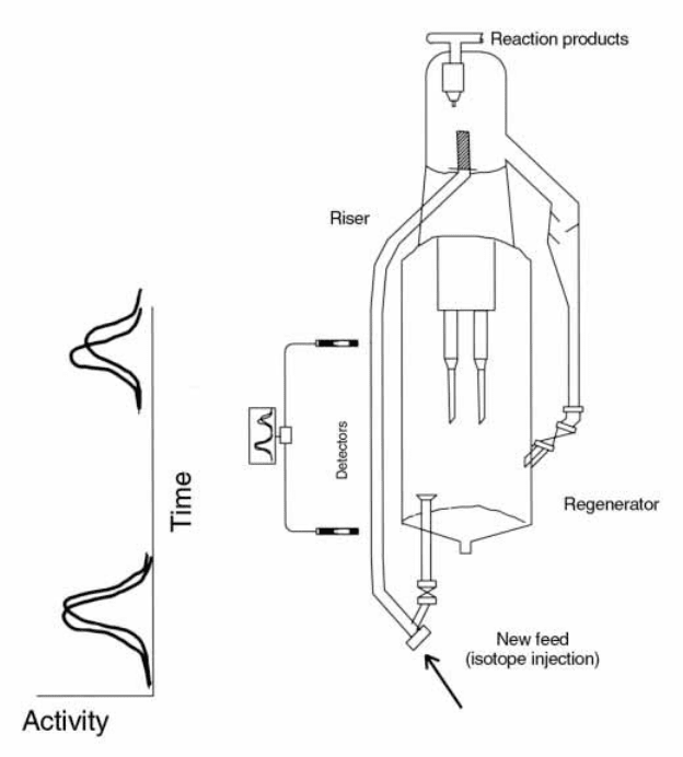
Figure 8.8. A schematic representation of an FCCU illustrating the investigation of
the dynamics of the gas phase and the catalyst in the riser.
locations throughout the re®nery plant and used to measure ¯ow velocities,
RTDs and mixing patterns for separate process streams through key elements
of the plant. For example, a radiotracer injected into the riser can be used to
provide information on the following processes:
feed and catalyst distribution in the riser feed zone;
catalyst and vapour velocities in the riser (slip factors);
determination of the ef®ciency of the riser termination device;
RTDs through the reactor and stripper;
mixing and ¯ow characteristics in the reactor and stripper; and
cyclone ef®ciencies, ¯ow distribution and residence times.
These are among the many tests which may be used to investigate a range
of generic issues including: (a) reasons for reduced plant yield; (b) the impact
of changes in operating conditions designed to enhance yield; and (c) the
accuracy of process modelling and simulation.
8.4.3 Radiotracers in the iron and steel industry
Applications of radiotracers to the iron and steel industry will be illustrated
here by an investigation of blast furnace operation. Blast furnaces are used
to reduce iron ore to iron using coke to which is added a ¯ux such as
limestone or quartzite. They comprise three sections: (a) the shaft which
takes the iron ore, coke and ¯ux; (b) the tuyeres or water-cooled nozzles
located around the furnace below the shaft through which air is blown into
the furnace at high pressure; and (c) the hearth at the base of the furnace
from which the molten iron and slag are tapped (Figure 8.9(a)). The
reduction of the iron ore occurs primarily through reactions with carbon
monoxide (CO). The ef®ciency with which the furnace works depends on
many factors including the quality of the coke, the uniform mixing of the
carbon monoxide gas with the iron ore (i.e. the absence of channelling) and
the ef®ciency of the hearth drainage.
The example quoted here describes an investigation of reduced yield due, it
was believed, to the development of a cold spot within the hearth furnace.
Two radiotracers,
198
Au and
60
Co were injected through two air blast nozzles
(tuyeres) located symmetrically with respect to the tap hole (Figure 8.9(b)).
During the tapping process, samples were taken every two minutes and
assayed simultaneously for the two isotopes using a g ray spectrometer. If the
furnace is behaving in accordance with speci®cation, the response curves
should overlap, re¯ecting similar residence time distributions in symmetri-
cally located regions of the furnace. If this is not so, the response curves
Applications of tracer technology to industry and the environment262
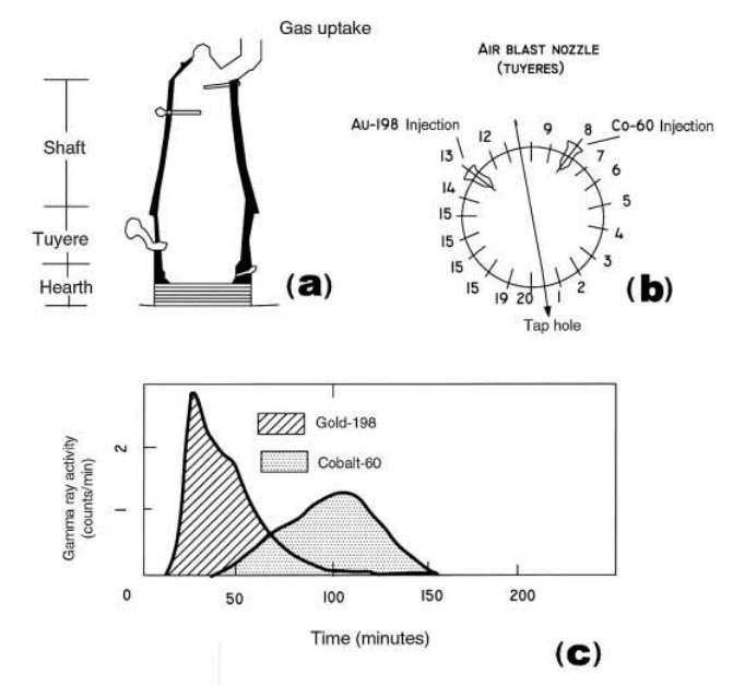
differ, indicating problems most likely due to the development of cold spots
within the hearth. Evidence for non-symmetrical behaviour and therefore of
an operational problem is clearly shown in Figure 8.9(c).
8.4.4 Inventories
Accurate measurements of activity ratios
The use of tracer dilution techniques to measure inventories has some
similarities to the determination of ¯ow rates by the constant injection
method. Both depend on the injection of a small accurately known quantity
8.4 Three case studies relating to industry 263
Figure 8.9. Radioisotope study: blast furnace ef®ciency. (a) Schematic repres enta-
tion of a blast furnace showing an air blast nozzle (tuyere) and a tap hole. (b) The
location of the tuyeres, the tap hole and the isotop e injection points. (c) The variation
with time of the activity of cobalt-60 and gold-198 in the iron sampled from the tap
hole (after Easey, 1988).
of tracer of speci®c activity C
0
(e.g. countrate per unit mass) into the bulk and
the measurement of the much lower speci®c activity c following complete
mixing. The basic equation (compare with Eq. (8.3)) is
M mC
0
=c (8.10)
where M and m are the masses of the total inventory and the added
radioactive tracer respectively (M4m) and C
0
/c is the ratio of speci®c
activities after background and other necessary corrections have been
made.
Key to the success of these applications is that the activity ratios are readily
measured with high accuracy. However, the ratio of the activities before and
after dilution C
0
/c, should be kept within, say 20 per cent of unity, and the
absolute activities should be neither too high nor too low to permit accurately
reproducible countrates. The most common method of ensuring that the
injected activities C
0
(Bq) and sampled activities c (Bq) are comparable is to
accurately dilute the high activity sample prior to the measurement with a
non-radioactive material of the same chemical composition. Assuming a
dilution factor of k
D
, Eq. (8.10) takes the form:
M mk
D
c
0
=c (8.11)
where c
0
is the speci®c activity of the tracer after dilution, i.e. C
0
= k
D
c
0
.
Mercury inventories
Tracer dilution methods are widely used for the accurate measurement of
mercury inventories in industrial plants designed for the production of
chlorine and sodium hydroxide by the electrolysis of sodium chloride
solutions. Although mercury electrodes are now no longer installed, many
older plants are still in operation and must be carefully monitored because of
the potential environmental impact of mercury release.
The radioactive mercury is produced in a research reactor by the irradia-
tion of stable mercury. Stable mercury is composed of seven isotopes, but in
practice only
196
Hg and
202
Hg form signi®cant irradiation products. Which of
the two is produced with the relatively greater intensity depends on the
irradiation time. The resulting radioisotopes are
197
Hg and
203
Hg (Table 8.1)
which have half lives of 64.1 h and 46.6 d respectively.
The method is simple in principle. The radioactive mercury, either
197
Hg or
203
Hg, of accurately known mass m and speci®c activity C
0
is added to the
large reservoir, the mass M of which is to be determined. After complete
mixing, a sample is taken and the speci®c activity c measured. A second
Applications of tracer technology to industry and the environment264
aliquot from the activated solution is diluted by a factor of k
D
yielding a
speci®c activity of c
0
. The inventory is then calculated from Eq. (8.11).
Which radionuclide is used for the investigation is determined by the time
required to achieve a homogeneous mixing of the added radioisotope with the
mercury in the reservoir. If this time can be expected to be no longer than a day
or two, irradiation conditions are chosen to maximise the yield of the shorter
lived
197
Hg. This approach is cheaper and leads to less residual radioactivity. If
complete mixing requires several days, the
197
Hg is allowed to decay and the
203
Hg is used as the tracer. The standards, samples and blanks are counted
under reproducible conditions using a g ray spectrometer. With careful work,
measurement accuracy better than 1% can be achieved routinely.
8.5 Conclusions
Radiotracer techniques have been extensively used throughout industry since
the mid-1950s to: (a) obtain an improved understanding of industrial
processes; (b) diagnose the reasons for industrial plant operating below
speci®cation; and (c) obtain accurate measurements of ¯ow rates, inventories
and mixing ef®ciencies.
A number of factors have in¯uenced the evolution of radiotracer technol-
ogies over the past four decades. First and foremost has been the enormous
developments in microprocessor technology, data processing and visualisa-
tion. Some classes of modern investigations require the rapid accumulation
and modelling of data from ®fty or more detectors.
However, radioisotope applications are highly regulated which complicates
their employment and means that alternative diagnostic technologies using
unregulated tracers are often preferred even when they have technical
limitations. Never-the-less, radiotracers remain in use for large and complex
tasks for which there are no practical alternatives and also for many others.
Developments of radioisotope technologies are not standing still. With the
passage of time, users are demanding more sophisticated data visualisation.
Techniques developed for the health sciences are being applied to industry.
For example, it is expected that computerised tomographic imaging using g
rays from radiotracers will eventually become a standard requirement in
many investigations.
Regulatory provisions for work with ionising radiations are designed to
ensure that doses to workers not only fully comply with all requirements, but
are, in addition, as low as reasonably achievable (the ALARA principle). The
challenge is therefore to maximise the amount of information which can be
obtained with the minimum use of radioactivity. Tracers are now seldom
8.5 Conclusions 265
used in isolation, but in conjunction with a range of investigation techniques.
They are increasingly seen as an essential aid to achieving the fundamental
aim of extending and validating numerical models of complex industrial
systems.
Applications of tracer technology to industry and the environment266
Chapter 9
Radionuclides to protect the environment
9.1 Introduction
The last chapter of our book will describe the use of radioisotopes for
assessing the impact of human activities on the environment. The range of
opportunities is very extensive as seen by the list of applications in Table 9.1
which is by no means complete. Emphasis will be placed on assessing such
impacts using two methods, described here as the mathematical modelling
approach and the archival approach.
1 The modelling approach. Due to recent vast increases in the power of computers,
applications of mathematical modelling techniques to environmental science are
now very widespread and underpin much of our detailed understanding of
processes in the oceans, the atmosphere and coastal and terrestrial ecosystems.
Since increasing use is being made of numerical models for scienti®c prediction
and environmental management, there is a growing need for independent
veri®cation of the model predictions. Tracer techniques are a powerful tool for
model validation, as will be demonstrated in several examples.
2 The archival approach. This approach to the study of environmental processes
involves using evidence from the past to understand the present and to assess
the future. The approach is implemented in two stages. The ®rst stage involves
the systematic dating of material which has accumulated layer by layer often
over long periods of time. Cores extracted from sediments, ice sheets, old
growth trees or massive corals are commonly used. From knowledge of the
dates of the samples and their locations in the core, it is possible to calculate the
average rate of growth or accumulation. This leads to the second stage of the
archival approach, which involves the measurement and interpretation of
indicators of past environmental change which are retained in the samples.
The age determination of samples using naturally occurring or environmental
isotopes involves three steps: (a) laboratory measurement of the activities of the
isotopes in carefully selected and prepared samples; (b) an assessment of the
267

Table 9.1.
Applications of tracer technology to the environment (see Tables 8.1 and 8.2 for decay
data).
No Environmental Sector Investigation Environmental
Impact
Radioisotope technique Comments
1.1
Environmental science
and engineering
Contaminant
dispersion
Evaluation of ocean
sewage outfalls
Potential impact on
public health, on the
recreational uses of
beaches, on ®sheries,
etc.
Arti®cial radiotracers
(tritium (HTO),
198
Au
or
99m
Tc) used to study
the dynamics of the
processes, and to
validate numerical
models
See Sections 9.3.3 and 9.3.4
1.2 Dynamics of inland
sewage ponds
Veri®cation of the
engineering design
speci®cation and
seeking causes for
non-compliance
Potential for
impacting on the local
river systems or
groundwater
Tritium and
99m
Tc
tracers used to measure
residence time
distributions and
identify `short
circuiting'
See Section 8.3.8
Essential that the residence
times of the sewage ponds
are suf®cient to ensure
complete aerobic oxidation
of pathogens
1.3 Ecological impact of
contaminant
dispersion
Quantifying the
distribution through
ecosystems of speci®c
heavy metals, organic
toxicants or nutrients
The degradation of
ecosystems must be
avoided if sustainable
development is to be
achieved
A wide range of
radionuclides are
available e.g.
65
Zn,
64
Cu and
54
Mn used to
study uptake of heavy
metals,
32
P for
phosphates, etc.
1.4 Discharges of air
pollutants from
industrial stacks
Validation of stack
dispersion models
Degradation of air
quality in the vicinity
of the stack
Chemical tracers
detectable with high
sensitivity are normally
used
2.1 Coastal and hydraulic
engineering
Applications to
dredging
Optimisation of
location of dumping
sites for dredge spoil
If not optimally
located, the dredge
spoil might for
example migrate into
a shipping channel, or
contaminate the
coastline
Dredge spoil labelled
with e.g.
198
Au,
46
Sc
and tracked
2.2 Harbour and port
development
Measurements of the
migration of sand and
sediment to e.g.
optimise the
alignment of dredged
shipping channels or
sea walls
Failure to optimise
alignment will give
rise to a need for
ongoing maintenance,
dredging and other
negative impacts
Sand and sediment
tracing (
198
Au,
192
Ir,
etc.) over periods from
1 week to 1 year used to
validate transport codes
Section 9.3.5
2.3 Hydraulics
Gauging of rivers
Tracer dilution
methods for calibration
or where gauging
stations are not
available
Section 9.3.2
3
Groundwater
Ef®ciency of recharge
to groundwater
basins; the dynamics
of groundwater ¯ow
Over-exploitation or
pollution of a
groundwater basin
can have impacts
which persist for tens
to hundreds of years
or longer
Cosmogenic isotopes
tritium,
14
C used to age
samples and hence
de®ne recharge areas
and migration rates;
stable isotopes D/H and
18
O/
16
O to study
groundwater source
and evidence for
mixing.
Isotopic methods are of
greatest value where
extensive hydraulic data are
unavailable

Table 9.1.
(contd)
No Environmental Sector Investigation Environmental
Impact
Radioisotope technique Comments
4.1
Sedimentation and
erosion
Sedimentation
Rate of accumulation
of sediments in
reservoirs and
estuaries
Loss of capacity of
reservoirs
Impact on harbour
development and on
the maintenance of
shipping channels
Sediments are cored;
the cores sectioned with
depth and the sections
dated
The dating technique
chosen depends on the time
scale:
137
Cs up to decades;
210
Pb to 100 y;
14
Cto
20 000 y;
230
Th/
234
Uto
250 000 y
4.2 Erosion
Rate of erosion and
accumulation of soils
in catchments
Impact of land use
change on soil erosion
and productivity
137
Cs pro®les over
catchments allow
quantitative estimates
of soil erosion and
accumulation
Such data can be used to
calibrate empirical
equations designed to
predict erosion rates over
geographical regions
5.1
Oceanography
Transport of solutes
and particulates in the
water column
Pro®les of `bomb'
isotopes, analysis of U,
Th and Ra isotopes in
the water column;
230
Th /
234
U in sea bed
Applications widespread,
e.g. impact of rivers on
coastal zone, transport of
nutrients, development of
coral reefs, etc.
5.2 Ocean currents Validation of ocean
current models
Global ocean currents
directly impact
climate
14
C used to measure the
residence times water
bodies
Residence time is the time
elapsed since the ocean
water sample was at the
surface
6.1 Global climate change
Atmospheric
transport
Validation of
atmospheric transport
models
Improved prediction
of postulated `green-
house' effects
Radon used to establish
whether air mass passed
over land
Improved prediction of
postulated `Green-house'
effects