Lyons W.C. (ed.). Standard handbook of petroleum and natural gas engineering.2001- Volume 1
Подождите немного. Документ загружается.

Fishing Operations and Equipment
1125
SHOklYPE
A
HARD
METAL)
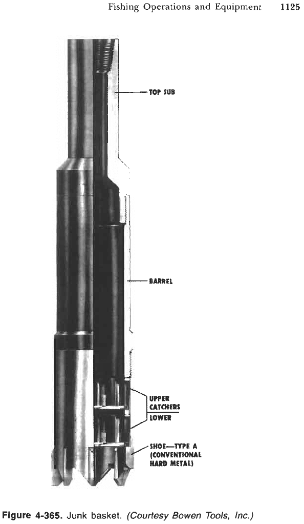
Figure
4-365.
Junk
basket.
(Courtesy
Bowen
Tools,
Inc.)
1126
Drilling and Well Completions
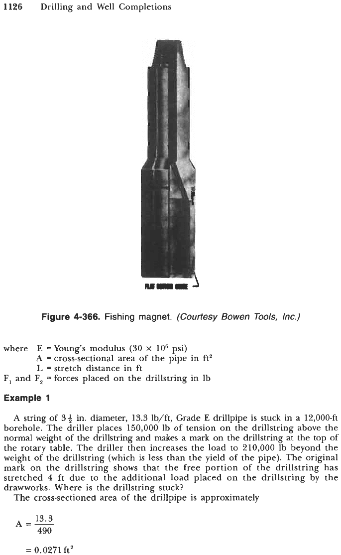
Figure
4-366.
Fishing magnet.
(Courtesy Bowen Tools, Inc.)
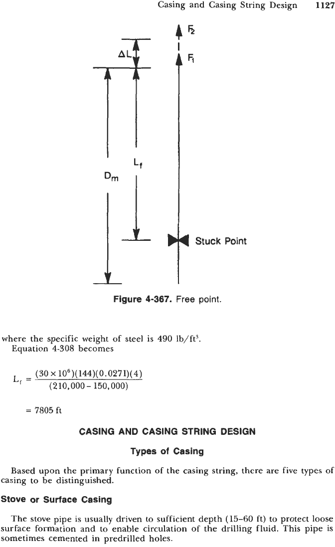
where
E
=Young's modulus
(30
x
lo6
psi)
A
=
cross-sectional area of the pipe in
ft2
L
=
stretch distance in ft
F,
and
F,
=
forces placed on the drillstring in lb
Example
1
A
string of
34,
in. diameter,
13.3
lb/ft, Grade
E
drillpipe is stuck in a 12,000-ft
borehole. The driller places
150,000
lb of tension on the drillstring above the
normal weight
of
the drillstring and makes a mark on the drillstring at the top of
the rotary table. The driller then increases the load to 210,000 lb beyond the
weight of the drillstring (which is less than the yield
of
the pipe). The original
mark on the drillstring shows that the free portion
of
the drillstring has
stretched
4
ft due to the additional load placed on the drillstring by the
drawworks. Where is the drillstring stuck?
The cross-sectioned area of the drillpipe is approximately
13.3
490
A=-
=
0.0271 ft'
Casing and Casing String Design
1127
D
J
4
Stuck Point
Figure
4-367.
Free
point.
where the specific weight of steel is
490
lb/ft3.
Equation
4-308
becomes
(30
x
106)(144)(0.0271)(
4)
L,
=
(210,000- 150,000)
=
7805
ft
CASING AND CASING STRING DESIGN
Types
of
Casing
Based upon the primary function
of
the casing string, there are five types of
casing to be distinguished.
Stove
or
Surface
Casing
The stove pipe is usually driven to sufficient depth
(15-60
ft) to protect loose
surface formation and
to
enable circulation of the drilling fluid. This pipe
is
sometimes cemented in predrilled holes.
1128
Drilling and Well Completions
Conductor String
This string acts as a guide for the remaining casing strings into the hole. The
purpose of conductor string is also to cover unconsolidated formations and to
seal off shallow overpressured formations. The conductor string is the first string
that is always cemented to the top and equipped with casing head and blowout
prevention (BOP) equipment.
Surface Casing
This is set deeply enough to protect the borehole from caving-in in loose
formations frequently encountered at shallow depths, and protects the freshwater
sands from contamination while subsequently drilling a deeper hole. In case the
conductor string has not been set, the surface casing is fitted with casing head
and BOP.
Intermediate Casing
Also called
protection string,
this is usually set in the transition zone before
abnormally high formation pressure is encountered, to protect weak formations
or to case off loss-of-circulation zones. Depending upon geological conditions,
the well may contain two or even three intermediate strings. Production string
(oil string) is the string through which the well is produced.
Intermediate or production string can be set as a liner string. The liner string
extends from the bottom of the hole upward to a point about
150-250
ft above
the lower end of the upper string.
Casing Program Design
Casing program design is accomplished by two steps. In the first step, the
casing sizes and corresponding bit sizes should be determined. In the second
step, the setting depth of individual casing strings ought to be evaluated. Before
starting the casing program design, the designer ought to know the following
basic information:
the purpose of the well (exploratory or development drilling);
geological cross-sections that should consist of type of formations, expected
hole problems, pore and formation’s fracture pressure, number and depth
of water, oil, gas horizons;
available rock bits and casing sizes;
load capacity of a derrick and mast if the type of rig has already been
selected.
Before starting the design, it must be assumed that the production casing size
and depth of the well have been established by the petroleum engineer in
cooperation with
a
geologist,
so
that the hole size (rock bit diameter) for the
casing may be selected. Considering the diameter of the hole, a sufficient
clearance beyond the coupling outside diameter must be provided to allow for
mud cake and also for a good cementing
job.
Field experience shows that the
casing clearance should range from about
1.0
in to
3.5
in. Larger casing sizes
require greater value of casing clearance. Once the hole size for production
string has been selected, the smallest casing through which
a
given bit will pass
Casing and Casing String Design
1129
is next determined. The bit diameter should be a little less (0.05 in.) than casing
drift diameter. After choosing the casing with appropriate drift diameter, the
outside coupling diameter of this casing may be found. Next, the appropriate
size
of
the bit should be determined
and
the procedure repeated.
Example
1
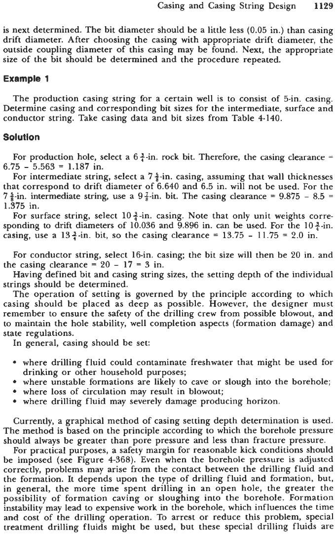
The production casing string for a certain well is to consist of 5-in. casing.
Determine casing and corresponding bit sizes for the intermediate, surface and
conductor string. Take casing data and bit sizes from Table 4-140.
Solution
For production hole, select a 6+-in. rock bit. Therefore, the casing clearance
=
6.75
-
5.563
=
1.187 in.
For intermediate string, select
a
7 +-in. casing, assuming that wall thicknesses
that correspond to drift diameter of 6.640 and 6.5 in. will not be used.
For
the
73n. inteimediate string, use
a
9%-in. bit. The casing clearance
=
9.875
-
8.5
=
1.375 in.
For surface string, select lo*-in. casing. Note that only unit weights corre-
sponding to drift diameters of 10.036 and 9.896 in. can be used. For the loq-in.
casing, use a 13th. bit,
so
the casing clearance
=
13.75
-
11.75
=
2.0
in.
For
conductor string, select 16-in. casing; the bit size will then be
20
in. and
the casing clearance
=
20
-
17
=
3
in.
Having defined bit and casing string sizes, the setting depth of the individual
strings should be determined.
The operation of setting is governed
by
the principle according
to
which
casing should be placed as deep as possible. However, the designer must
remember
to
ensure the safety
of
the drilling crew from possible blowout, and
to maintain the hole stability, well completion aspects (formation damage) and
state regulations.
In general, casing should be set:
where drilling fluid could contaminate freshwater that might be used for
drinking
or
other household purposes;
where unstable formations
are
likely
to
cave
or
slough into the borehole;
9
where loss of circulation may result in blowout;
where drilling fluid may severely damage producing horizon.
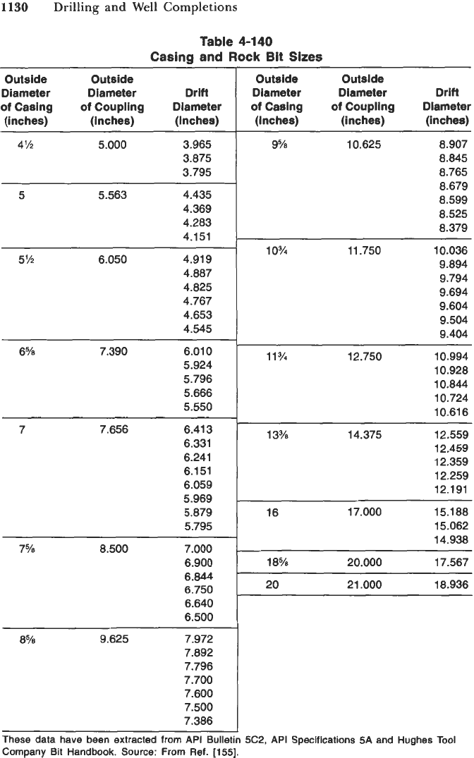
Currently, a graphical method
of
casing setting depth determination is used.
The method is based on the principle according to which the borehole pressure
should always be greater than pore pressure and less than fracture pressure.
For practical purposes, a safety margin for reasonable kick conditions should
be imposed (see Figure 4-368). Even when the borehole pressure is adjusted
correctly, problems may arise from the contact between the drilling fluid and
the formation. It depends upon the type of drilling fluid and formation, but,
in general, the more time spent drilling in an open hole, the greater the
possibility of formation caving
or
sloughing into the borehole. Formation
instability may lead to expensive work in the borehole, which influences the time
and cost
of
the drilling operation. To arrest
or
reduce this problem, special
treatment drilling fluids might be used, but these special drilling fluids are
1130
Drilling and Well Completions
Table
4-140
Casing
and
Rock
Bit Sizes
Outside Outside
Diameter Diameter Dr ift
of
Casing
of
Coupling Diameter
(inches) (inches) (inches)
4% 5.000 3.965
3.875
3.795
5 5.563 4.435
4.369
4.283
4.151
5% 6.050 4.91 9
4.887
4.825
4.767
4.653
4.545
6% 7.390 6.01 0
5.924
5.796
5.666
5.550
7 7.656 6.41 3
6.331
6.241
6.151
6.059
5.969
5.879
5.795
7% 8.500 7.000
6.900
6.844
6.750
6.640
6.500
8% 9.625 7.972
7.892
7.796
7.700
7.600
7.500
7.386
Outside Outside
Diameter Diameter Drift
of
Casing
of
Coupling Diameter
(inches) (inches) (inches)
~ ~
9% 10.625 8.907
8.845
8.765
8.679
8.599
8.525
8.379
~ ~ ~~
10% 11.750 10.036
9.894
9.794
9.694
9.604
9.504
9.404
11v4
12.750 10.994
10.928
10.844
10.724
10.61 6
13% 14.375 12.559
12.459
12.359
12.259
12.191
16 17.000 15.188
15.062
14.938
18% 20.000 17.567
20
21.000 18.936
These data have been extracted
from
API Bulletin
5C2,
API Specifications
5A
and Hughes Tool
Company Bit Handbook. Source:
From
Ref. [155].
Casing and Casing String Design
1131
0'
2000
4000
PRESSURE GRADIENT
(psilft)
1
I
I.
I
I
I
I
I
1
I
I
"
'\
Ref:
Adoms.
N..
"Well
Control
-
Problems
and Solutions".
-
Tulsa,
1980.
\
Petroleum Publishing
Co..
'\
-
'\,
-
\
'\
-
\,
Fracture Pressure
-
\\,/
Gradient
-
\
-
\
-
',
-
\
\
-
Figure
4-368.
Well planning.
(From
Ref.
[757].)
expensive. Therefore, the casing and drilling fluid programs depend on each
other, and solving the issue of the correct casing setting depth evaluation is a
rather complicated, optimizing problem.
Example
2
Suppose that in some area the expected formation pressure gradient is
0.65
psi/ft and formation fracture pressure gradient is
0.85
psi/ft.
A
gas-bearing
1132 Drilling and Well Completions
formation is expected at depth of 15,000 ft. Assume that a gas kick occurs that,
to be removed from the hole, induces a surface pressure
of
2,000
psi. The first
intermediate casing is set at a depth of
7,200
ft. Determine the setting depth
for the second intermediate casing string if required in given conditions. Assume
drilling fluid pressure gradient
=
0.65 psi/ft.
Solutlon
The formation fracture pressure line is
P,
=
(0.85)(D)
The borehole pressure line is
Pbh
=
2000
+
(0.65)(D)
so
(0.85)(D)
=
2,000
+
(0.65)(D)
2000
0.2
D
=
-
10,OOOft
The second intermediate casing string is required and must be set at a depth
of
10,000
ft.
Casing
Data
SpeciaZ
Note:
Nothing in this specification should be interpreted
as
indicating
a preference by the committee for any material or process, nor as indicating
equality between the various materials or processes. In the selection of materials
and processes, the purchaser must be guided by his or her experience and by
the service for which the pipe is intended.
Casing is classified according to its manner of manufacture, steel grade,
dimensions and weights, and the type of coupling.
The following are excerpts from API Spec. 5A, 35th Edition, March 1981.
Process
of Manufacture
Casing and liners shall be seamless or electric welded as defined below and
as
specified on the purchase.
a. Seamless pipe is defined as
a
wrought steel tubular product made without
a welded seam. It is manufactured by hot working steel
or,
if
necessary, by
subsequently cold finishing the hot-worked tubular product to produce the
desired shape, dimensions and properties.
b. Electric-welded pipe is defined as pipe having one longitudinal seam
formed by electric-flash welding or electric-resistance welding, without the
addition
of
extraneous metal. The weld seam of electric-welded pipe shall
be heat treated after welding to a minimum temperature
of
1,000"F
(5SSoC),
or
processed in such a manner that no untempered martensite
remains.
Casing and Casing String Design
1153
Physical Properties (Section 4,
API
Specification
5A)
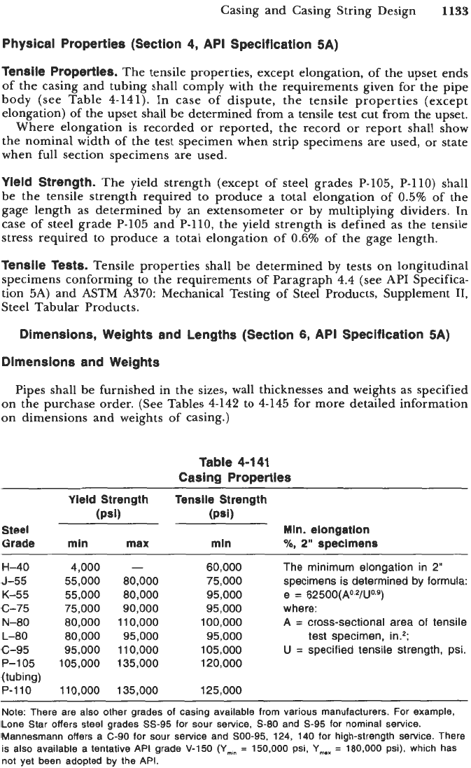
Tensile Properties.
The tensile properties, except elongation, of the upset ends
of the casing and tubing shall comply with the requirements given for the pipe
body (see Table 4-141). In case of dispute, the tensile properties (except
elongation) of the upset shall be determined from a tensile test cut from the upset.
Where elongation is recorded
or
reported, the record
or
report shall show
the nominal width of the test specimen when strip specimens are used,
or
state
when full section specimens are used.
Yield Strength.
The yield strength (except of steel grades P-105, P-110) shall
be the tensile strength required to produce a total elongation of 0.5% of the
gage length as determined by an extensometer
or
by multiplying dividers. In
case of steel grade P-105 and P-110, the yield strength
is
defined as the tensile
stress required to produce a total elongation of
0.6%
of the gage length.
Tensile Tests.
Tensile properties shall be determined by tests on longitudinal
specimens conforming to the requirements of Paragraph 4.4 (see API Specifica-
tion 5A) and ASTM A370: Mechanical Testing of Steel Products, Supplement 11,
Steel Tabular Products.
Dimensions, Weights and Lengths (Section
6,
API
Specification
5A)
Dimensions and Weights
Pipes shall be furnished in the sizes, wall thicknesses and weights as specified
on the purchase order. (See Tables 4-142 to 4-145 for more detailed information
on dimensions and weights of casing.)
Table 4-141
Casing Properties
Vieid Strength Tensile Strength
(Psi) (Psi)
Steel
Grade
H-40
J-55
K-55
c-75
N-80
L-80
c-95
P-105
(tubing)
P-110
min max
4,000
-
55,000
80,000
55,000
80,000
75,000
90,000
80,000
110,000
80,000
95,000
95,000 11
0,000
105,000 135,000
11
0,000
135,000
min
60,000
75,000
95,000
95,000
100,000
95,000
105,000
120,000
125,000
Min. elongation
%,
2"
specimens
The minimum elongation in
2"
specimens is determined by formula:
e
=
62500(A0.2/U0.9)
where:
A
=
cross-sectional area
of
tensile
U
=
specified tensile strength, psi.
test
specimen, in.*;
~~ ~ ~ ~~ ~ ~~ ~
Note: There are also other grades
of
casing available from various manufacturers. For example,
Lone Star offers steel grades
SS-95
for sour service,
S-80
and
5-95
for nominal service.
Mannesmann offers a
C-90
for sour service and
SOO-95, 124,
140
for high-strength service. There
is also available
a
tentative API grade
V-150
(Ymm
=
150,000
psi,
Y,,,
=
180,000
psi), which has
not yet been adopted by the API.
Table
4-142
Short Round-Thread Casing Dimensions and Weights
Nominal
Calculated Weight
Weight9
r
7
Sue: Threads Threads2
Outside and
wall
lnside
Plain
and
Diameter,
Coupling,
l%i+e+
-em,
End,
Gouging
in.
Ibperft
m. m.
lb/ft
D
t
d
WI.0
e...
Nominal
Calculated Weight
Weight:'
.
Size: Threads
Threads2
Outside and Wall
Wide
Plain
and
Diameter,
Coupliog,
l%i+a~ess,
eeter,
End,
Co~~fng
in.
lbperft
ID.
m.
Ib/ft
D
t
d
Wl"
e...
4M 9.50 0.205
4M 10.50 0.224
4M 11.60 0.250
5 11.50 0.220
5 13.00 0.253
5 15.00
0.296
5M 14.00 0.244
5% 15.50 0.275
514 17.00 0.304
6%
20.00 0.288
6%
24.00 0.352
7 17.00 0.231
7 20.00 0.272
7
23.00 0.317
7 26.00 0.362
7% 24.00
0.300
7% 26.40 0.328
8%
24.00 0.264
8%
28.00
0.304
8% 32.00 0.352
8% 36.00 0.400
4.090
4.052
4.000
4.560
4.494
4.408
5.012
4.950
4.892
6.049
5.921
6.538
6.456
6.366
6.276
7.025
6.969
8.097
8.017
7.921
7.825
9.40
10.23
11.35
11.23
12.83
14.87
13.70
15.35
16.87
19.49
23.58
16.70
19.54
22.63
25.66
23.47
25.56
23.57
27.02
31.10
35.14
4.20
3.80
3.40
5.40
4.80
4.20
5.40
4.80
4.40
11.00
9.60
10.00
9.40
8.00
7.20
15.80
15.20
23.60
22.20
20.80
19.40
9%
9%
9%
10%
10%
10%
1
0%
10%
1134
1134
11%
11%
13%
13%
1338
13%
13%
16
16
16
18%
20
20
20
32.30 0.312
36.00 0.352
40.00 0.395
32.75 0.279
40.50 0.350
45.50 0.400
51.00 0.450
55.50 0.495
42.00 0.333
47.00 0.375
54.00 0.435
60.00 0.489
48.00 0.330
54.50 0.380
61.00 0.430
68.00
0.480
72.00 0.514
65.00 0.375
75.00 0.438
84.00 0.495
87.50 0.435
94.00 0.438
106.50 0.500
133.00 0.635
9.001
8.921
8.835
10.192
10.050
9.950
9.850
9.760
11.084
11.OOo
10.880
10.772
12.715
12.615
12.515
12.415
12.347
15.250
15.124
15.010
17.755
19.124
19.000
18.730
31.03
34.86
38.94
31.20
38.88
44.22
49.50
54.21
40.60
45.56
52.57
58.81
45.98
52.74
59.45
66.11
70.60
62.58
72.72
81.97
84.51
91.51
104.13
131.33
24.40
23.00
21.40
29.00
26.40
24.40
22.60
20.80
29.60
27.60
25.00
22.60
33.20
30.80
28.40
25.80
24.20
42.60
38.20
34.20
73.60
47.00
41.60
30.00
'Nominal
weights,
threads and coupling
(Col.
2
),
are
shown
for
the
purpose
of
identification in ordering.
Weight gain due
to
end finishing.
Source:
From
Ref.
[1511.