Lyons W.C. (ed.). Standard handbook of petroleum and natural gas engineering.2001- Volume 1
Подождите немного. Документ загружается.

037
ft
-
2675
fi
9861
fi
1'"
4
t
Casing and Casing String Design
1165
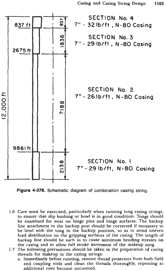
SECTION
No.4
7"
-
321bIft
,
N-80
Casing
SECTlON
No.
3
7"
-
29
Ib/ft
,
N
-80
Casing
SECTION
No.
2
7"
-
261bIft. N-80
Casing
SECTION
No.
I
7"
-
29
Ib/ft,
N-80
Casing
Figure
4-378.
Schematic diagram
of
combination casing string.
1.6
Care must be exercised, particularly when running long casing strings,
to ensure that slip bushing or bowl is in good condition. Tongs should
be examined for wear on hinge pins and hinge surfaces. The backup
line attachment to the backup post should be corrected if necessary to
be level with the tong in the backup position,
so
as
to
avoid uneven
load distribution on the gripping surfaces of the casing. The length
of
backup line should be such as
to
cause minimum bending stresses on
the casing and to allow full stroke movement of the makeup tong.
1.7
The following precautions should be taken in the preparation of casing
threads for makeup in the casing strings:
a.
Immediately before running, remove thread protectors from both field
and coupling ends and clean the threads thoroughly, repeating as
additional rows become uncovered.
1166
Drilling and Well Completions
b. Carefully inspect the threads. Those found damaged, even slightly,
should be laid aside unless satisfactory means are available for
correcting thread damage.
c. The length
of
each piece of casing shall be measured prior to
running.
A
steel tape, calibrated in decimal feet to the nearest
0.01
ft,
should be used. The measurements should be made from the outer-
most face of the coupling or box to the position on the externally
threaded end where the coupling or the box stops when
the
joint is
made up powertight. On round-thread joints this position is the place
of the vanish point on the pipe; on buttress-thread casing, this
position is to the base of the triangle stamp on the pipe; on extreme
line casing to the shoulder on the externally threaded end. The total
of the individual length
so
measured will represent the unloaded
length of the casing string.
Note:
The actual length under tension in the hole can be obtained
from pertinent graphs or approximately calculated from
(4-323)
where
AL
=
casing elongation in in.
L
=
original length of casing in in.
E
=
casing modulus of elasticity (for steel
E
=
(30)(106)
lb/in.*)
y,
=
casing specific weight, lb/ix~.~ (for steel
ys
=
0.283
Ib/h5)
yf
=
fluid specific weight in lb/in.3
p
=
Poisson’s ratio (for steel
p
=
0.28)
Formula
4-323
is valid for any consistent system of units and is
applicable to vertical holes.
d. Check each coupling for makeup. If the stand-off is abnormally great,
check the coupling for tightness. Tighten any loose couplings after
thoroughly cleaning the threads and applying fresh compound over
the entire thread surfaces, and before pulling the pipe into the
derrick.
e. Before stubbing, liberally apply thread compound to the entire
internally and externally threaded areas. It
is
recommended that high-
pressure modified thread compound
as
specified in
API
Bulletin
5A2:
“Bulletin on Thread Compounds” be used except in special cases
where severe conditions are encountered; it
is
recommended that high
pressure silicone thread compound as specified in Bulletin
5A2
be used.
f.
Place a clean thread protector on the field end of the pipe
so
that
the thread will not be damaged while rolling pipe on the rack and
pulling into the derrick. Several thread protectors
may
be cleaned
and
used repeatedly for this operation.
g. If a mixed string is to be run, check to determine that appropriate
casing will be accessible on the pipe rack when required according
to program.
h.
Connectors used as tensile and lifting members should have their
thread capacity carefully checked to assure that the connector can
safely support the load.
i. Care should be taken when making
up
pup joints and connectors to
assure that the mating threads are of the same size and type.
Casing and Casing String Design
1167
1.8
Drifting of casing. It is recommended that each length of casing be
drifted for its entire length just before running with mandrels con-
forming to the requirements
of
Standard
5A
“Specification for Casing,
Tubing and Drill Pipe.” Casing that will not pass the drift test should
be laid aside.
1.9
Lower
or
roll each piece of casing carefully to the walk without dropping.
Use rope snubber if necessary. Avoid hitting casing against any part of
derrick
or
other equipment. Provide a hold back rope at window. For
mixed and unmarked strings, a drift
or
“jack rabbit” should be run
through each length of casing when it
is
picked up from the catwalk
and pulled onto the derrick floor, to avoid running a heavier length or
one with a lesser inside diameter than called for in the casing string.
Stubbing, Making
Up,
and Lowering
1.10
Do not remove thread protector from field end
of
casing until ready
to stub.
1.11
If
necessary, apply thread compound over entire surface of threads just
before stubbing.
1.12
In stubbing, lower casing carefully to avoid injuring threads. Stub
vertically, preferably with assistance
of
someone
on
the stubbing board.
If the casing stub tilts to one side after stubbing, lift up, clean and correct
any damaged thread
with
threecornered file, then carefully remove any
filings to ensure that threads
are
engaging properly and not cross-threading.
If spinning line is used, it should pull close to the coupling.
Note:
Recommendations in paragraphs
1.13
and
1.14
for casing makeup
apply to the use
of
power tongs.
For
recommendations of makeup of
casing with spinning lines and conventional tongs, see paragraph
1.15.
1.13
The use
of
power tongs for making up casing made desirable the
establishment of recommended torque values
for
each size, weight and
grade of casing. Early studies and tests indicated that torque values are
affected by a large number
of
variables, such as variations in taper, lead,
thread height and thread form; surface finish; type
of
thread compound;
length of thread; weight and grade of pipe; etc. In view of the number
of variables and the extent that those variables, alone or in combination,
could affect the relationship of torque versus madeup positions, it was
evident that both applied torque and madeup position must be con-
sidered. Since the API joint pullout strength form& in API Bulletin
5C2
contains several of the variables believed to affect torque, the use of
a
modification
of
this formula to obtain torque values was investigated.
Torque values obtained by taking
1%
of the calculated pull-out value
were found to be generally comparable to values obtained by field
makeup tests using API-modified thread compound in accordance with
API Bulletin 5A2. This procedure was, therefore, used to establish the
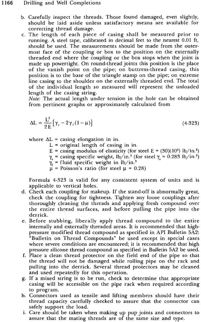
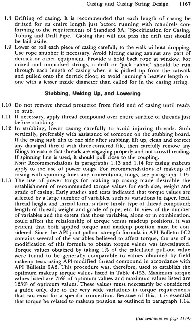
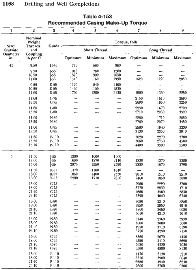
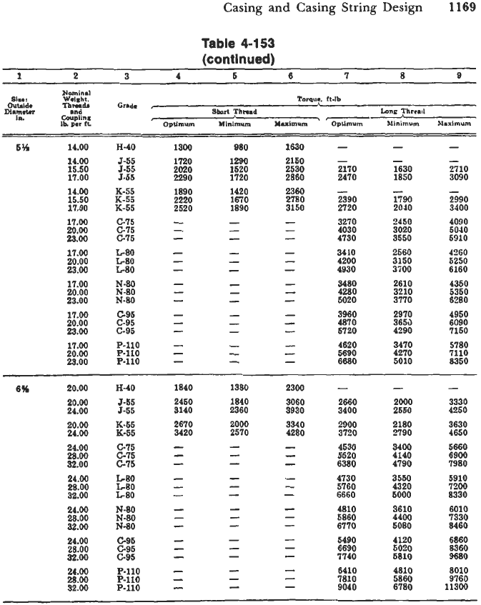
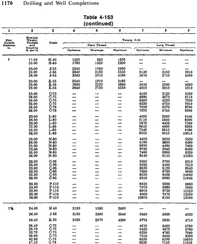
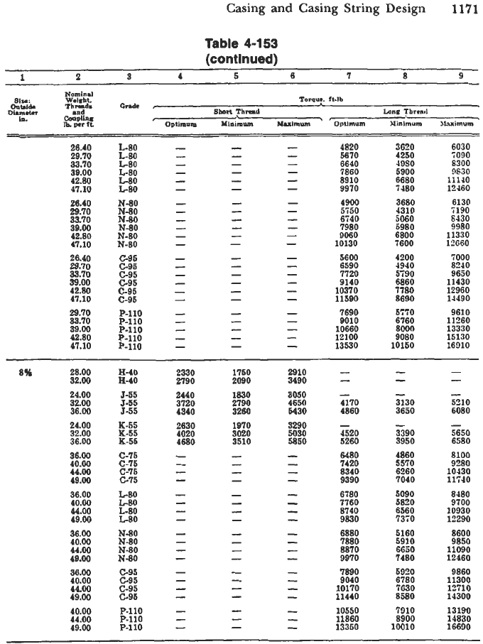
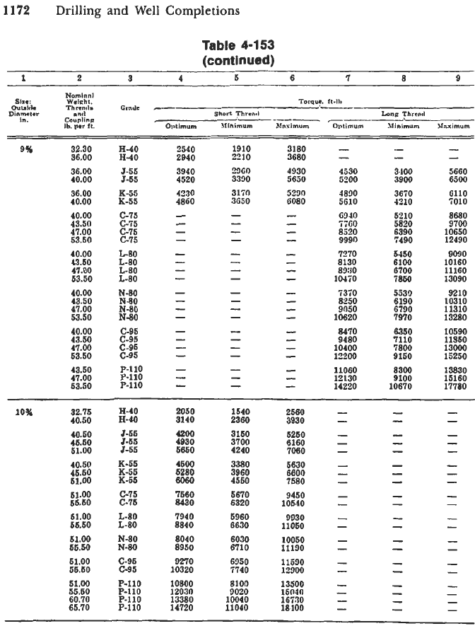
optimum makeup torque values listed in Table
4-153.
Maximum torque
values listed are 75% of optimum values and maximum values listed are
125% of optimum values. These values must necessarily be considered
a guide only, due to the very wide variations in torque requirements
that can exist
for
a specific connection. Because
of
this, it is essential
that torque be related to makeup position as outlined in paragraph
1.14.
(text
continued
an
page
11
74)
1168
Drilling
and
Well
Completions
Table
4-153
Recommended Casing Make-up Torque
1
2
3
4
5
6
7
8
9
Nominal
Weight Toque, ft-lb
Size:
Threads,
Grade
r
Outside and
Short
Thread
Long
Thread
Diameter
Coupling
r
-.
in.
Ibnerft
Ontimum
Mium
bhximum
Oetimum
Minimum
&ximum
4K 9.50
H-40
9.50 5-55
10.50 5-55
11.60 5-55
9.50 K-55
10.50 K-55
11.60 K-55
11.60 G75
13.50 G75
11.60
L80
13.50
La0
11.60
N-80
13.50
N-80
11.60 G95
13.50 G95
11.60 P-110
13.50 P-110
15.10 P-110
770
1010
1320
1540
1120
1460
1700
580
760
990
1160
840
1100
1280
960
1260
1650
1930
1400
1830
2130
-
-
-
1620
-
-
1800
2150
2600
2230
2710
2280
2760
2580
3130
3020
3660
4400
-
-
-
1220
-
-
1350
1610
1950
1670
2030
1710
2070
1940
2350
2270
2750
3300
-
-
-
2030
-
-
2250
2690
3250
2790
3390
2850
3450
3230
3910
3780
4580
5500
5
11.50 5-55 1330 1000 1660
-
- -
13.00 5-55
1690 1270
2110 1820
1370 2280
15.00 5-55 2070 1550
2590 2230
1670 2790
11.50 K-55 1470
1100
1840
-
-
-
13.00 K-55 1860
1400 2330
2010
1510 2510
15.00 K-55 2280
1710
2850 2460 1850 3080
15.00
GI5
- -
-
2960
2220
3700
18.00
G75
- -
-
3770 2830
4710
21.40
GI5
-
-
-
4660 3500
5830
24.10
GI5
-
-
-
5390 4040
6740
-
-
3080 2310 3850
15.00
L80
-
-
-
3950 2950 4910
18.00
L-80
-
21.40
L80
-
- -
4860 3650 6080
- -
5610 4210 7010
24.10
L-80
-
15.00
N-80
-
-
-
3140 2360
3930
18.00
N-80
- -
-
4000
3000 5000
21.40
N-80
-
-
-
4950 3710
6190
24.10
N-80
-
-
-
5720 4290
7150
-
-
3560 2670 4450
15.00 G95
-
18.00 G95
-
-
-
4550 3410 5690
21.40 C95
-
-
-
5620 4220 7030
24.10 G95
-
-
-
6500 4880 8130
-
-
4170 3130 5210
15.00 P-110
-
18.00 P-110
- -
-
5310 3980 6640
21.40 P-110
-
- -
6580 4940 8230
24.10 P-110
-
-
-
7600 5700 9500
Casing and Casing String Design
1169
Table
4-153
(continued)
1
2 3
4
5
6
7
8
B
"in81
=ht.
Tomu*.
It-lb
-
-
-
5% 14.00
H-40
1300
980
1690
2150
- -
-
1520 2170 1630 2710
2470 1850 3090
12W
2530
14.00 5-55 10
15.50 5-55 2020
17.00 J-55 2290 1720 2860
14.00 K-55 1890 1420 2360
-
-
15.50 K-56
2220
1670 2780
2390 1790 2990
17.00 K-55 2520
1890 3150
2720 2010
3400
-
-
-
3270
2450 4090
-
-
4030
3020 5040
-
-
4730
3550 5910
17.00 C-75
20.00 C75
23.00
c-75
-
-
-
-
3410 2560 4260
-
-
4200 3150 5250
17.00 680
23.00
L-80
-
- -
4930 3iOO 6160
20.00
LBO
-
-
-
-
3480 2610 4350
-
-
-
4280 3210 5350
17.00
N-80
23.00 N.80
-
-
-
5020 3770 6280
20.00
N-80
-
-
-
3960
2970 4950
-
-
4870 3653 6090
17.00 C95
23.00 C-95
-
-
-
5720 4290 7150
20.00 c-95
3470 5780
5690 7110
8350
4620 4270
17.00 P-110
29.00 P-110
- -
-
6680 5010
20.00 P-110
-
-
-
-
-
20.00
24.00
20.00
24.00
24.00
28.00
32.00
24.00
28.00
32.00
24.00
28.00
32.00
24.00
28.00
32.00
24.00
28.00
92.00
H40
J-55
5-55
K-55
K-55
G76
c-75
C-76
LBO
680
L-80
N-80
N-80
N-80
C-95
c-95
c.95
P-110
FllO
P-110
1840
2460
8140
2670
3420
1380
1840
2360
2000
2570
2300
3060
3930
3340
4280
2660
3400
2900
3720
4530
5520
5380
4730
5760
6660
4810
5860
6770
5490
6690
7740
6410
7810
9040
2000
2650
2180
2790
3400
4140
4790
3550
4320
5000
3610
4400
5080
4120
5020
6810
4810
5860
6780
3330
4250
3630
4650
5660
69M)
7980
5910
7200
8330
6010
7330
8460
6860
8360
9680
8010
9760
11300
1170
Drilling and
Well
Completions
Table 4-153
(continued)
1
2 3
4
5
6 7
5
9
Torque.
It-lb
Short
Tbnad
ton.
Thread
Omhum
Nislmum
Mnximum
Optimum Minimum luimm
Nomind
and
Gmplinr
Ib.
wr
fL
cnde
c
s1.c:
pl&t;
OuWdc
Diumem
In.
I
17.00
20.00
20.00
23.00
26.00
20.00
25.00
26.00
23.00
26.00
29.00
32.00
36.00
88.00
29.00
26.00
29.00
32.00
35.00
38.00
25.00
26.00
29.00
32.00
35.00
38.00
26.00
29.00
32.00
35.00
38.00
H-40
H-40
3-55
3-55
J-65
K-55
K-55
K-55
G75
(2-75
c-75
C-75
c-75
GI6
L-80
L-50
L-80
L-80
L-80
L-80
N-80
N-80
N-80
N-80
N-80
N-80
E95
G95
G95
E95
E95
c-95
P-110
P-110
P-110
P-110
P-110
-
-
- -
- -
3130 2350
3670 2750
3410 2560
4010 3010
-
-
4160 3120
4890 3670
5620 4220
6330 4750
7030 5270
7670 5750
4350 3260
5110 3830
5870 4400
6610 4960
7340 6510
5010 6010
6930 5200
7970 5980
8970 6730
9960 7470
10570 8150
-
-
-
3910
4590
4260
5010
5200
6110
7030
7910
8790
9590
5440
6390
7340
8260
9180
10010
5530
6490
7460
8400
9330
10180
6310
7410
8540
9600
10660
11640
8660
9960
11210
12450
13590
-
7% 24.00 €I-40 2120 1590 2650
-
- -
26.40
5-56
3150
2360 3940
3460
2600 4330
26.40 K-65 3420
2570
4280 3'770
2830 4710
C-75
(3-75
c-75
c-75
c-75
C-76
4610
5420
6350
7510
8520
9530
3460
4070
4760
5630
6390
7150
5760
6780
7940
9390
10650
11910
Casing
and
Casing
String
Design
1171
Table
4-153
(continued)
-
-
-
4820
3020 6030
-
-
-
5670 4250 7090
26.40 L-80
-
-
6640 0980
8300
29.70 L-80
-
-
-
7860 5900
9630
33.70
LBO
-
-
-
8910 6680
11140
39.00 L-80
47.10 L-80
-
-
-
9970 7480
12460
42.80
LBO
-
26.40
29.70
33.70
39.00
42.80
47.10
N-80
N-80
N-80
N-80
N-80
N-80
4900
Si50
6740
7980
9060
10130
3680
4310
5060
5980
6800
7600
6130
7190
S430
9980
11330
12660
26.40
29.70
33.70
39.00
42.80
47.10
C-95
C-95
c-95
G95
c-95
42-95
5600 4100
6590 4940
7720
3790
9140
6860
10370 7780
11590 8690
7690
57iO
9010
6760
12100 9080
13530 10150
10660
Boon
7000
8240
9650
11430
12960
14490
29.70
33.70
39.00
42.80
47.10
P-110
P-110
P-110
P-110
P-110
9610
11260
13330
15130
16910
1750
2090
1830
2790
3260
2910
3490
3050
4650
6430
H-40
H-40
5-55
5-55
5-55
2330
2790
2440
3720
4340
2630
4020
4680
28.00
85
92.00
24.00
32.00
36.00
3130
3650
3390
3950
-
5210
6080
5650
6580
-
4170
4860
K-55
K-55
K-56
1970
3020
3510
3290
5030
5850
24.00
32.00
36.00
-
4520
5260
6480
7420
8340
9390
4860
5570
6260
7040
8100
9280
10430
11740
36.00
40.00
44.00
49.00
c-75
c-75
c-75
C75
36.00
40.00
44.00
49.00
LBO
LBO
L-80
LBO
N-80
N-80
N-80
N-80
6780
7760
8740
9830
5090
5890
6560
'i3iO
8080
9700
10930
12290
6880
7880
8870
9970
7890
9040
10170
11440
5160
6910
6660
7480
5920
6780
SC30
8580
8600
9850
11090
12460
9860
11300
12710
14300
36.00
40.00
44.00
49.00
36.00
40.00
44.00
49.00
40.00
44.00
49.00
C95
c-95
c-95
C95
P-110
P-110
P-110
10550
11860
13360
7810
8900
10010
13190
14830
16690
1172
Drilling and
Well
Completions
Table
4-153
(continued)
1
2
S
4 5 6
7
8
9
32.30
"
36.00
36.00
40.00
36.00
40.00
40.00
43.50
47.00
53.50
40.00
43.50
47.00
53.50
40.00
43.50
47.00
53.50
40.00
43.50
47.00
63.50
43.50
47.00
53.50
H-40
H-40
J-55
J-55
K-55
IC-55
C-75
c-75
c-75
G75
G80
L-80
L-80
L-80
N-80
N-80
N-80
N-80
c-95
c-95
c-95
c-95
P-110
P-110
P-110
-
-
4530
5200
4830
5610
God0
5760
8520
9990
7270
8130
8030
10470
1310
8950
9050
10620
8470
9480
10400
13200
11060
12130
14230
I-
-
-
3400
3900
3670
4210
5210
5820
6390
'7490
5450
6100
6700
7850
5539
6190
6730
7970
6350
7110
7800
9150
8300
9100
10670
-
-
5660
6500
GllO
7010
8680
9700
10650
12490
9090
10160
11160
13090
9210
11310
13280
10590
11950
13000
15250
13830
15160
17780
10310
-
-
-
-
-
-
32.75
E40
2060
1540
2580
40.50
H-40
3140
2360
3930
40.50 3-66
1200
3150
5250
-
-
-
45.50 J-55
4930
3700
6160
-
-
-
51.00
J-55 5650
4240
7080
-
-
-
3380
6630
-
-
-
5280
6600
-
-
61.00
K-55
6060
4550
7580
-
-
-
4500
3960
40.50 K-55
45.50 K-55
51.00 G75 7560 5670 9450
-
-
-
55.50 C-75 8430 6520 10540
-
-
-
51.00
L-80
7940 5960 0930
-
-
-
55.50 L-80 8840
6630
11050
-
-
-
61.00
N-80 8040 6030
10050
-
-
-
55.50 N-80 8950
6710
11190
-
-
-
51.00 '2-95 9270
-
-
6950 11500
55.50 G95 10320 7740
12900
-
-
-
-
-
-
-
-
-
-
-
-
-
-
51.00
P-110
10800
8100
13500
55.60 P-110
12030
9020
15n10
60.70
P-110
13380
10040 16iRO
-
65.70
P-110
14720
11040
18
100
-
Casing and Casing String Design
1173
Table
4-153
(continued)
1
2 3 4
5
6
7
a
9
Temuc.
rut.
Short
Thd
lane
Ihmd
Xominill
sir:
Wcinht.
=nd
C0"Pll.l
Ib
wr
ft
Outsid.
Thmds
Grade
,
'
Optimum
Midmum
Yuimrm
Ortinwu Minimum
Mmxinum
Diameter
in.
3840
-
-
-
11% 42.00 H-40
3070
2300
47.00 J-55 4770 3580 5960
1100 54.00 J-55 5630 4260
60.00
J-55 6490 4870 8110
6360
- -
-
47.00 K-55 5090 3820
1580
54.00 K-55 6060 4550
60.00
K-55 6930 5200 8660
8690 6520
10860
-
-
-
60.00
C-75
60.00
680 9130 6850 11410
-
-
-
60.00
N-80 9240 6930 11550
-
-
-
10660
8000 13330
-
-
-
60.00
C-95
60.00
P-110 12420
9320
16530
-
-
-
-
- -
-
-
-
-
-
-
-
-
-
-
-
-
18% 48.00
54.50
61.00
68.00
54.50
61.00
68.00
68.00
72.00
68.00
72.00
68.00
12.00
68.00
12.00
68.00
72.00
H-40
5-55
5-55
5-55
K-55
K-55
K-55
C-75
GI5
680
680
N-80
N-80
c-95
G95
P-110
P-110
3220
5140
5950
6750
2420
3860
4460
5060
5470
6330
1180
9060
9780
9620
10290
9630
10400
11140
12040
12970
14020
4100
4750
5390
6800
7340
7140
7720
7220
7800
8360
9030
9130
10520
4030
-
6430
7440
8440
-
6840
7910
8980
-
11330
-
12230
-
11900
12860
12040
13000
13930
15050
16210
-
17530
-
-
-
-
-
-
-
-
-
-
-
-
-
-
-
*16 65.00 H-40
-
4390
75.00 J-55
-
7100
84.00 5-55
-
8170
-
-
7520
75.00
K-65
84.00 K-55
-
8650
*18K
87.50
H-40
-
5590
87.50 5-55
-
7540
87.50 K-55
-
7940
-
-
-
-
-
-
-
-
-
-
-
- -
-
-
-
-
-
-
-
-
-
-
-
-
-
-
~~ ~~
-
-
-
-
a20
94.00
H-40
-
5810
-
1840
94.00 J-55
-
9130
106.50 J-55
133.00
5-56
-
11920
94.00
K-55
-
8240
106.50
K-55
-
9600
133.M)
K-55
-
12530
-
-
-
-
9070
-
10570
-
13800
-
-
9550
-
-
11130
-
-
-
14530
-
-
-
-
-
-I"
pa-.
1.14h
for
nr.~.-me
imtnmwna
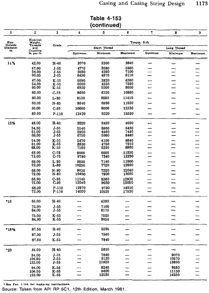
Source: Taken
from
API
RP
5C1,
12th
Edition,
March
1981.
1174
Drilling and Well Completions
(text
continued
from
puge
1167)
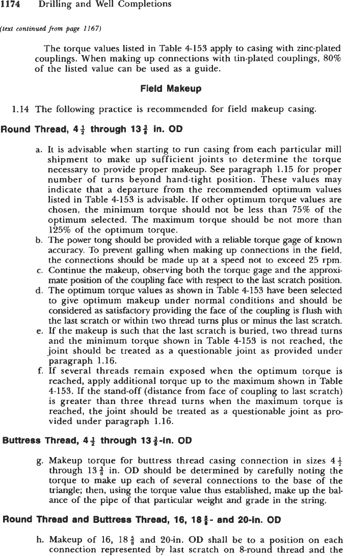
The torque values listed in Table
4153
apply to casing with zinc-plated
couplings. When making up connections with tin-plated couplings,
80%
of the listed value can be used as a guide.
Fieid Makeup
1.14
The following practice is recommended for field makeup casing.
Round Thread,
44
through 133 in.
OD
a. It is advisable when starting to run casing from each particular mill
shipment to make up sufficient joints to determine the torque
necessary to provide proper makeup. See paragraph
1.15
for proper
number of turns beyond hand-tight position. These values may
indicate that a departure from the recommended optimum values
listed in Table
4-153
is advisable. If other optimum torque values are
chosen, the minimum torque should not be less than
75%
of the
optimum selected. The maximum torque should be not more than
125%
of the optimum torque.
b. The power tong should be provided with a reliable torque gage of known
accuracy. To prevent galling when making up connections in the field,
the connections should be made up at a speed not to exceed
25
rpm.
c. Continue the makeup, observing both the torque gage and the approxi-
mate position of the coupling face with respect to the last scratch position.
d. The optimum torque values as shown in Table
4153
have been selected
to give optimum makeup under normal conditions and should be
considered as satisfactory providing the face of the coupling is flush with
the last scratch
or
within two thread turns plus or minus the last scratch.
e. If the makeup is such that the last scratch is buried, two thread turns
and the minimum torque shown in Table
4-153
is not reached, the
joint should be treated as a questionable joint as provided under
paragraph
1.16.
f. If several threads remain exposed when the optimum torque is
reached, apply additional torque up to the maximum shown in Table
4-153.
If the stand-off (distance from face of coupling to last scratch)
is greater than three thread turns when the maximum torque is
reached, the joint should be treated as a questionable joint as pro-
vided under paragraph
1.16.
Buttress Thread,
4
3
through 13 +-in.
OD
g. Makeup torque for buttress thread casing connection in sizes
4+
through
139
in.
OD
should be determined by carefully noting the
torque to make up each of several connections to the base of the
triangle; then, using the torque value thus established, make up the bal-
ance of the pipe of that particular weight and grade in the string.
Round Thread and Buttress Thread,
16,
18#- and 20-in.
OD
h. Makeup of
16,
18%
and 20-in.
OD
shall be to a position on each
connection represented by last scratch on 8-round thread and the