Lyons W.C. (ed.). Standard handbook of petroleum and natural gas engineering.2001- Volume 1
Подождите немного. Документ загружается.

Hoisting System
525
block weighs
9,000
lb and the traveling block weighs
4,500
lb. Assume that there
are no other tools hanging in the derrick and that the deadline is attached to
the rig floor across from the drawworks in its normal position (see Figure
4-7).
Assume the standard deduction of
2%
per working line to calculate eh.
eh
=
1.00
-
0.02(8)
=
0.84
From Equation
4-13
600
000
+
600,000
+
9,
ooo
0.84(8)
8
F,
=
604,500
+
-
-
=
604,500
+
89,286
+
75,000
+
9,000
=
786,786
lb
Drawworks
The drawworks is the key operating component of the hoisting system. On
most modern rotary drilling rigs, the prime movers either operate the hoisting
drum within the drawworks or operate the rotary table through the transmission
within the drawworks. Thus the drawworks
is
a complicated mechanical system
with many functions
[1,7].
Functions
The drawworks does not carry out only hoisting functions on the rotary
drilling rig. In general, the functions of the drawworks are as follows:
1.
Transmit power from the prime movers (through the transmission) to its
hoisting drum to lift drill string, casing string, or tubing string, or to pull
in excess of these string loads to free stuck pipe.
2.
Provide the braking systems on the hoist drum for lowering drill string,
casing string, or tubing string into the borehole.
3.
Transmit power from the prime movers (through the transmission) to the
rotary drive sprocket to drive the rotary table.
4.
Transmit power to the catheads for breaking out and making up drill string,
casing string, and tubing string.
Figure
4-9
is a schematic of drawworks together with the prime mover power
source.
Design
The
drawworks basically contains the hoist drum, the transmissions,
the
brake
systems, the clutch systems, rotary drive sprocket, and cathead. Figure
410
shows
a
schematic of the drawworks.
The power is provided to the drawworks by the prime movers at the master
clutch (see Figure
49)
and
is
transmitted to the master clutch shaft via sprockets
and roller chain drives. The speed and the torque from the prime movers are
controlled through the compound. The compound is a series
of
sprockets, roller
chain drives, and clutches that allow the driller to control the power
to
the
526
Drilling and Well Completions
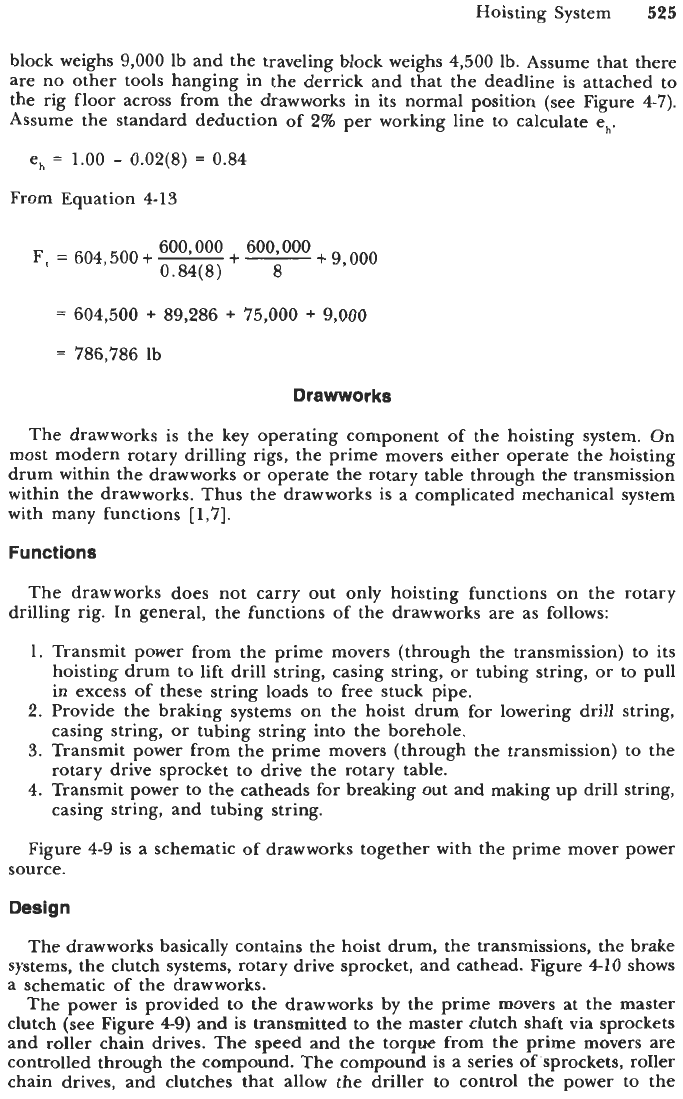
1
16
11
9.
Rotary drive air clutch countershaft
10. Driller’s console
11.
Drum low air clutch
12. High gear
13. Reverse gear
14. Intermediate gear
15.
Low
gear
16.
Power
flow selector*
1.
Drive to pump
2. Master clutch
3. Generator
4. Air compressor
5. Washdown pump
6.
Sand reel drive
7.
Drum high air clutch
8.
Auxiliary brake
*Note: This item is shown as a manually operated clutch.
This,
of
course,
on
an actual rig would be air actuated.
Figure
4-9.
Power train on a drawworks
with
accessories.
drawworks. The driller operates the compound and the drawworks (and other
rig functions) from a driller’s console (see Figure
4-11).
With the compound, the driller can obtain as many as
12
gears working
through the drawworks transmission.
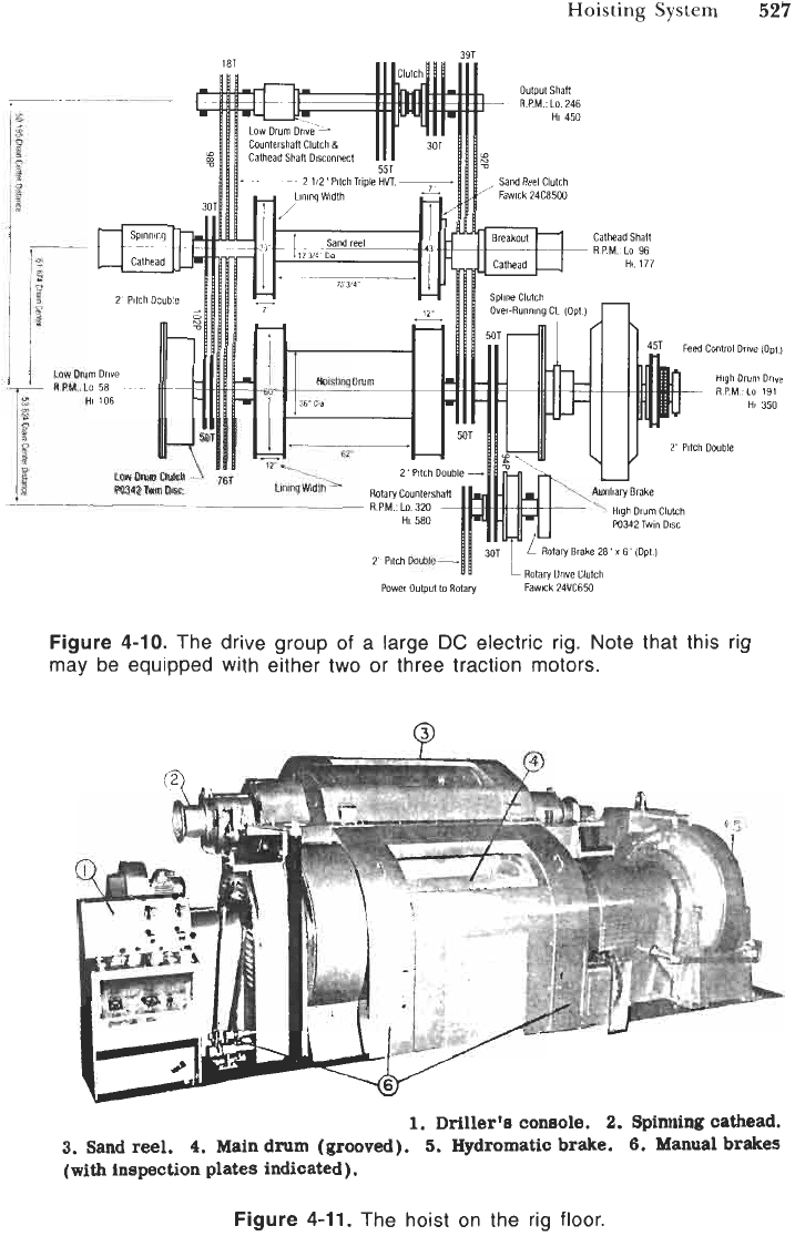
In Figure
4-11,
the driller’s console is at the left of the drawworks. Also, the
hoisting drum and sand reel can be seen. The driller’s brake control is between
the driller’s console and the drawworks to control the brake systems
of
the
hoisting drum.
Hoisting
Drum.
The hoisting drum (usually grooved) is probably the most
important component on the drawworks. It is through the drum that power is
transmitted to lift the drill string with the drilling line (wire rope) wound on
the drum. From the standpoint
of
power requirements
for
hoisting, the ideal
Hoisting
System
527
i
Rotary
Brake
20
x
6"
(Opt
Rotary
Dnve
Clutch
Fawick 24VC650
Power
output
lo
Rotary
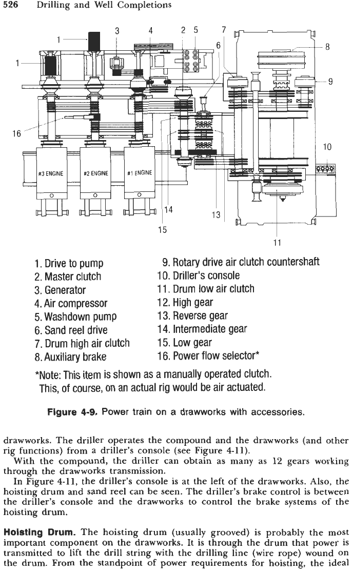
Figure
4-10.
The drive group
of
a large
DC
electric rig. Note that this rig
may be equipped with either two or three traction motors.
1.
Driller's
coneole.
2.
Spinning cathead.
3.
Sand reel.
4.
Main drum
(grooved).
5.
Hydromatic brake.
6.
Manual brakes
(with
inspection plates indicated).
Figure
4-11.
The hoist on the rig floor.
528
Drilling and Well Completions
drum would have a diameter as small as possible and a width as great as
possible. From the standpoint of drilling line wear and damage, the hoisting
drum would have the largest drum diameter. Therefore, the design of the
hoisting drum must be compromised to obtain an optimum design. Thus, the
hoist drum is usually designed to be as small as practical, but the drum is
designed to be large enough to permit fast line speeds in consideration of
operation and economy.
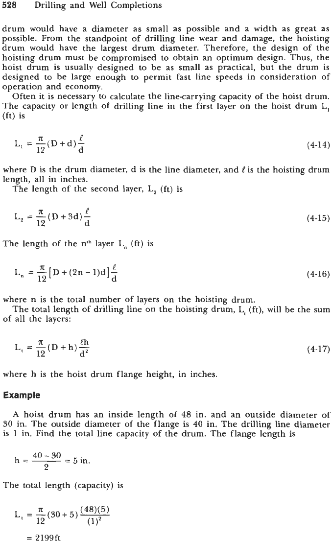
Often it is necessary to calculate the line-carrying capacity of the hoist drum.
The capacity or length of drilling line in the first layer on the hoist drum
L,
(ft)
is
A
e
L,
=
-(D+d)- (4-14)
12 d
where
D
is the drum diameter, d is the line diameter, and
is the hoisting drum
length, all in inches.
The length of the second layer,
L,
(ft) is
A
e
L,
=
-(D+3d)-
12 d
The length of the nth layer
Ln
(ft) is
A
e
Ln
=
-[D+(2n-l)d]-
12 d
(4-15)
(4-16)
where n is the total number of layers on the hoisting drum.
of all the layers:
The total length of drilling line on the hoisting drum,
Lt
(ft),
will be the sum
A
eh
L,
=
-(D+h)-
12 d2
(4-17)
where h is the hoist drum flange height, in inches.
Example
A
hoist drum has an inside length of
48
in. and an outside diameter
of
30 in. The outside diameter of the flange is 40 in. The drilling line diameter
is 1 in. Find the total line capacity of the drum. The flange length is
The total length (capacity) is
L,
=
-(30+5)-
A
(48x5)
12
=
2199ft
Hoisting System
529
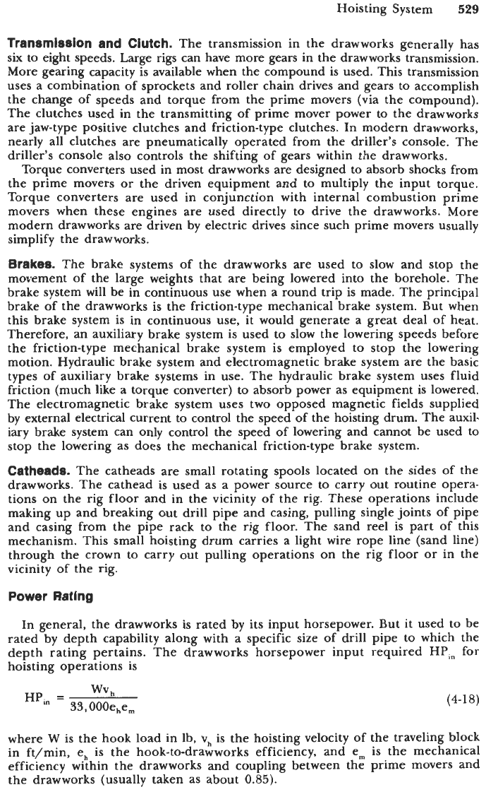
Transmission and Clutch.
The transmission in the drawworks generally has
six
to eight speeds. Large rigs can have more gears in the drawworks transmission.
More gearing capacity is available when the compound is used. This transmission
uses a combination of sprockets and roller chain drives and gears
to
accomplish
the change of speeds and torque from the prime movers (via the compound).
The clutches used in the transmitting
of
prime mover power to the drawworks
are
jaw-type positive clutches and friction-type clutches. In modern drawworks,
nearly all clutches are pneumatically operated from the driller’s console. The
driller’s console also controls the shifting of gears within the drawworks.
Torque converters used in most drawworks are designed to absorb shocks from
the prime movers
or
the driven equipment and to multiply the input torque.
Torque converters are used in conjunction with internal combustion prime
movers when these engines are used directly to drive the drawworks. More
modern drawworks are driven by electric drives since such prime movers usually
simplify the drawworks.
Brakes.
The brake systems of the drawworks are used to slow and stop the
movement of the large weights that are being lowered into the borehole. The
brake system will be in continuous use when a round trip is made. The principal
brake
of
the drawworks is the friction-type mechanical brake system. But when
this brake system is in continuous use, it would generate a great deal of heat.
Therefore, an auxiliary brake system is used to slow the lowering speeds before
the friction-type mechanical brake system
is
employed
to
stop the lowering
motion. Hydraulic brake system
and
electromagnetic brake system are the basic
types of auxiliary brake systems in use. The hydraulic brake system uses fluid
friction (much like
a
torque converter) to absorb power as equipment is lowered.
The electromagnetic brake system uses two opposed magnetic fields supplied
by external electrical current to control the speed
of
the hoisting drum. The auxil-
iary
brake system can only control the speed of lowering and cannot be used to
stop the lowering as does the mechanical friction-type brake system.
Catheads.
The catheads are small rotating spools located
on
the sides of the
drawworks. The cathead is used as a power source to carry out routine opera-
tions on the rig floor and in the vicinity of the rig. These operations include
making up and breaking out drill pipe and casing, pulling single joints of pipe
and casing from the pipe rack to the rig floor. The sand reel is part of this
mechanism. This small hoisting drum carries a light wire rope line (sand line)
through the crown to carry out pulling operations on the rig floor
or
in the
vicinity of the rig.
Power Rating
In general, the drawworks is rated by its input horsepower. But it used to be
rated by depth capability along with a specific size of drill pipe to which the
depth rating pertains. The drawworks horsepower input required
HPi,
for
hoisting operations
is
wv
h
HP,
=
33,000ehe,
(4-18)
where
W
is the hook load in lb,
vh
is the hoisting velocity of the traveling block
in ft/min, e,, is the hook-to-drawworks efficiency, and e,,, is the mechanical
efficiency within the drawworks and coupling between the prime movers and
the drawworks (usually taken as about
0.85).
530
Drilling and Well Completions
Example
It is required that the drawworks input power be able to lift
600,000
lb at
a
rate of
50
ft/min. There are eight working lines between the traveling block
and the crown block. Three input power systems are available:
1,100, 1,400,
and
1,800
hp. Which
of
the three will be the most appropriate? The value of eh is
e,,
=
1.00
-
0.02(8)
=
0.84
The input horsepower is
600,000(
50)
33,000( 0.84)(
0.85)
HP,
=
=
1273.2
The input power system requires
1400
hp.
Drilling and Production Hoisting Equipment
[9,10]
Drilling and production hoisting equipment includes:
1.
2.
3.
4.
5.
6.
7.
a.
9.
10.
11.
12.
13.
14.
15.
Crown block sheaves and bearings:
The stationary pulley system at the top
of
the derrick or mast.
Traveling blocks:
A
heavy duty pulley system that hangs in the derrick and
travels up and down with the hoisted tools. It is connected to the crown
block with a wire rope that ultimately runs to the hoisting drum.
Block-to-hook adapters:
A
metal piece that attaches to the bottom
of
the
traveling block and serves as the mount for the hook.
Connectors and link adapters.
Drilling
hooks:
The hook that attaches to the traveling block to connect
the bail
of
the swivel.
Tubing and sucker rod
hooks:
Hooks connected to the traveling block for
tubing and sucker-rod hoisting operations.
Elevator
Zinks:
The elevator is a hinged clamp attached to the hook and
is used to hoist drill pipe, tubing, and casing. The actual clamp is in a
pair of links that in turn attaches to a bail supported on the hook.
Casing, tubing and drill
pipe
elevators.
Sucker rod elevator.
Rotary swivel bail adaptors:
A
bail adaptor that allows the bail of the swivel
to be grasped and hoisted with elevators.
Rotary swivels.
The swivel connecting the nonrotating hook and the
rotating kelley while providing a nonrotating connection through which
mud enters the kelley.
Spiders:
The component of the elevator that latches onto the hoisted item.
Deadline tiedowns:
The deadline is the nonmoving end of the wire rope
from the hoisting down through the crown and traveling blocks. This end
is anchored at ground level with a tiedown.
Kelley spinners, when used
as
tension members:
An adapter between the swivel
and the kelley that spins the kelley for rapid attachment and disattachment
to joints
of
drill pipe.
Rotary
tables,
as
structural members:
The rotary table rotates to turn the
drill string. It
is
also used to support the drill string during some phases
of operation.
Hoisting System
531
16.
Tension members
of
subsea handling equipment.
17.
Rotary
slips:
Wedging devices used to clamp the tool string into the rotary
table. The wedging action is provided by friction.
Material Requirements
Castings.
Steel castings used in the manufacture of the main load carrying
components of the drilling and production hoisting equipment shall conform
to ASTM A781: “Common Requirements for Steel and Alloy Castings for General
Industrial Use,” and either an individual material specification listed therein or
a proprietary material specification that as a minimum conforms to ASTM A781.
Forgings.
Steel forgings used in the manufacture of the main load carrying
components
of
the equipment shall conform to ASTM
A668:
“Steel Forgings,
Carbon and Alloy, for General Industrial Use” and ASTM A778: “Steel Forgings,
General Requirements.” A material specification listed in ASTM A788 or a
proprietary specification conforming to the minimum requirements of ASTM
A788
may be used.
Plates, Shapes, and Bar Stock.
Structural material used in the manufacture
of main load carrying components of the equipment shall conform
to
applicable
ASTM or API specifications covering steel shapes, plates, bars, or pipe, or a
proprietary specification conforming to the minimum requirements of applicable
ASTM or appropriate standard. Structural steel shapes having a specified minimum
yield strength less
than
33,000
psi, or steel pipe having a specified minimum yield
strength less than
35,000
psi shall not be used.
Design Rating and Testing
All hoisting equipment shall be rated in accordance with the requirements
specified herein. Such ratings shall consist
of
a maximum load rating for all
items, and a main-bearing rating for crown blocks, traveling blocks, and swivels.
The traveling block
and
crown block ratings are independent
of
wire rope size and
strength.
Such ratings shall be calculated as specified herein and in accordance
with good engineering practices. The ratings determined herein are intended
to apply to new equipment only.
Maximum Load Rating.
The maximum load ratings shall be given in tons
(2,000-lb units). The size class designation shall represent the dimensional
interchangeability and the maximum rated load of equipment specified herein.
The recommended size classes are as follows (ton):
5
40
350
10
65 500
15 100 650
25 150
750
250
1,000
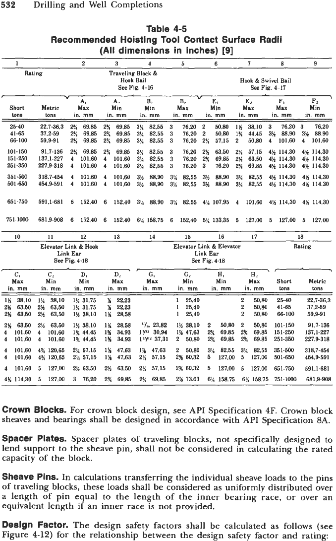
For purpose of interchangeability contact radii shall comply with Table
4-5.
Maximum
Load
Rating
Bases.
The maximum load rating will
be
based on the
design safety factor and the yield strength of the material. Crown block beams
are an exception and shall be rated and tested in accordance with API Spec
4E:
“Specification for Drilling and Well Servicing Structures.”
532
Drilling and Well Completions
Table
4-5
Recommended Hoisting Tool Contact Surface Radii
(All
dimensions in inches)
[9]
~ ~
1
2
3 4 5
6
7
8
9
Rating Traveling Block
&
Hook Bail
See
Fig.
4-16
Hook
&
Swivel Bail
See
Fig.
4-17
"
A,
A?
B,
Bz
E,
El
F,
Fd
'
Short Metric Max
Min
Min
Max
Min
Max
Mu
Min
tons
tons in.
mm
in.
mm
in.
mm
in.
mm
in.
mm
in.
mm
in.
mm
in.
mm
25-40
22.7-36.3
2%
69.85
2%
69.85
3% 82.55
3
76.20
2
50.80
1%
38.10 3
76.20
3
76.20
41-65
37.2-59
2%
69.85
2%
69.85
3% 82.55
3
76.20
2
50.80
1%
44.45
3% 88.90 3%
8890
66-100
59.9-91
2%
69.85
2%
69.85
3% 82.55
3
76.20
2%
57.15
2
50.80
4 101.60
4 101.60
101-150 91.7-136
2%
69.85
2%
69.85
3% 82.55
3
76.20
2%
63.50
2%
57.15 4% 114.30
4% 114.30
151-250
137.1-227 4 101.60
4
101.60
3% 82.55
3
76.20
2%
69.85
2%
63.50 4% 114.30
4% 114.30
251-350 227.9-318
4 101.60
4 101.60
3% 82.55
3
76.20
3
76.20
2%
69.85
4%
114.30 4% 114.30
351-500
318.7-454 4 101.60
4
101.60 3%
88.90
3%
82.55
3% 88.90
3%
82.55 4% 114.30
4% 114.30
501-650 454.9-591
4 101.60
4 101.60 3%
88.90
3%
82.55
3%
88.90
3% 82.55
4% 114.30 4% 114.30
651.750 591.1-681
6
152.40
6
152.40 3% 88.90 3% 82.55 4% 107.95 4 101.60 4% 114.30 4% 114.30
751-1000 681.9-908
6
152.40 6 152.40
6%
158.75
6
152.40 5% 133.35
5
127.00 5 127.00 5 127.00
10
11
12
13
14
1.5
16
17
18
Elevator Link
&
Hook
Link Ear
See
Fig.
4-18
Elevator Link
&
Elevator
Link Ear
See
Fig.
4-18
Rating
\-
C,
c,
D,
D,
G,
c,
H,
n1
Max Min Min Max
MW
Min Min Max Short Metric
in.
mm
1%
38.10
2%
63.50
2%
65.50
2%
63-50
4 101.60
4 101.60
4 101.60
4 101.60
4 101.60
4% 114.30
in.
mm
1%
38.10
2%
63.50
2%
63.50
2%
63.50
4 101.60
4 101.60
4% 120.65
4% 120.65
5 127.00
5 127.00
in.
mm
1%
31.75
1%
31.75
1%
38.10
1%
38.10
1%
44.45
1%
44.45
2%
57.15
2%
57.15
2%
63.50
3
76.20
in.
mm
%
22.23
%
22.23
1%
28.58
1%
28.58
1%
34.93
1%
34.93
1%
47.63
1%
47.63
2%
63.50
2%
69.85
in.
mm
'
Yt.
23.82
17"
30.94
l'Yp"
37.31
1%
47.63
2%
57.15
2%
57.15
2%
69.85
in.
mm
1
25.40
1
25.40
1
25.40
1%
38.10
1%
47.63
2
50.80
2
50.80
2%
60.32
2%
60.32
2%
73.03
in.
mm
in.
mm
tons
2
50.80 25-40
2
50.80 41-65
2
50.80 66-100
2
50.80
2
50.80 101-150
FA
69.85
2%
69.85 151-250
2%
69.85
2%
69.85
251-350
3% 82.55 3% 82.55 351-500
5 127.00
5
127.00 501-650
5 127.00 5 127.00 651-750
6% 158.75
6%
158.75 751-1000
tons
22.7-36.3
37.2-59
59.9-91
91.7-136
137.1-227
227.9-318
318.7-454
454.9-591
591.1-681
681.9-908
Crown
Blocks.
For
crown block design, see
API
Specification 4F. Crown block
sheaves and bearings shall be designed in accordance with
API
Specification
8A.
Spacer Plates.
Spacer plates of traveling blocks, not specifically designed to
lend support to the sheave pin, shall not be considered in calculating the rated
capacity of the block.
Sheave Pins.
In calculations transferring the individual sheave loads to the pins
of traveling blocks, these loads shall be considered as uniformly distributed over
a length
of
pin equal to the length of the inner bearing race, or over an
equivalent length if an inner race is not provided.
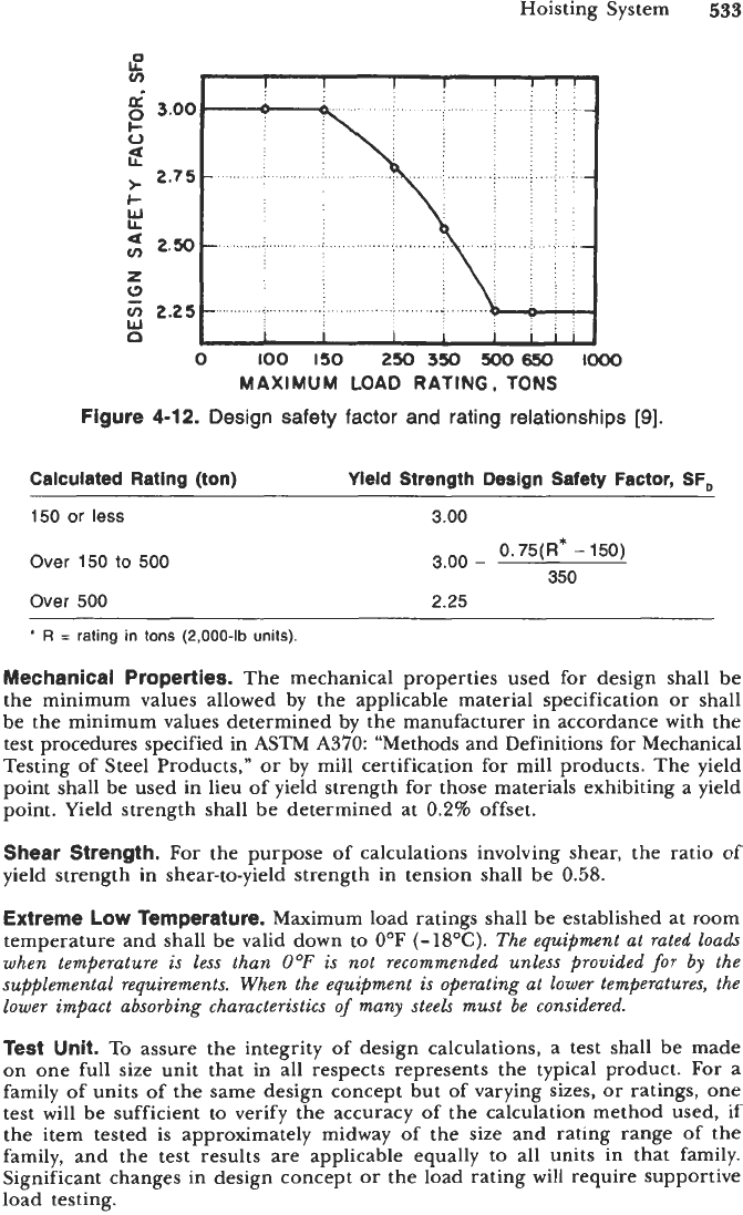
Deslgn Factor.
The design safety factors shall be calculated as follows (see
Figure
4-12)
for the relationship between the design safety factor and rating:
Hoisting System
533
0
too
150
250
350
500650
to00
MAXIMUM
LOAD
RATING.
TONS
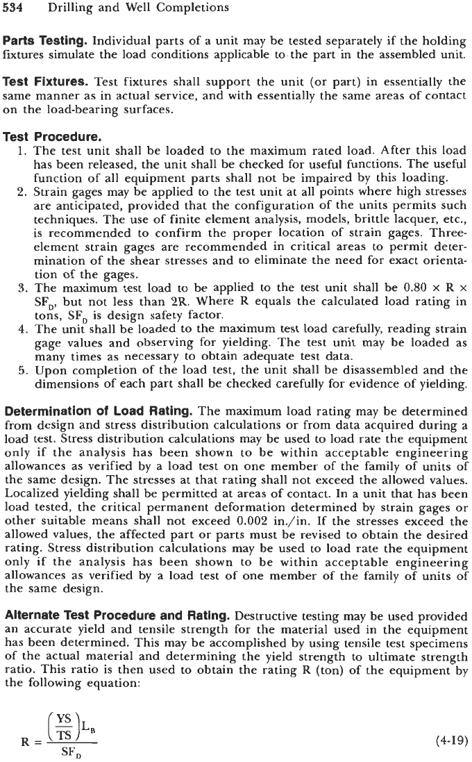
Figure
4-12.
Design safety factor and rating relationships
[Q].
Calculated Rating (ton)
Yield Strength
Design
Safety Factor,
SF,
150
or less
Over
150
to
500
Over
500
3.00
3.00
-
2.25
0.75(R*
-
150)
350
+
R
=
rating in tons
(2,000-lb
units).
Mechanical Properties.
The mechanical properties used for design shall be
the minimum values allowed by the applicable material specification or shall
be the minimum values determined by the manufacturer in accordance with the
test procedures specified in ASTM
A370:
“Methods and Definitions for Mechanical
Testing of Steel Products,” or by mill certification for mill products. The yield
point shall be used in lieu of yield strength for those materials exhibiting a yield
point. Yield strength shall be determined at
0.2%
offset,
Shear Strength.
For
the purpose of calculations involving shear, the ratio of
yield strength in shear-to-yield strength in tension shall be
0.58.
Extreme Low Temperature.
Maximum load ratings shall be established at room
temperature and shall be valid down to
OOF
(-l8OC).
The equipment at rated loads
when temperature
is
less than
0°F
is not recommended unless provided
for
by the
supplemental requirements. When the equipment is operating at lower temperatures, the
lower impact absorbing characteristics
of
many steels must be considered.
Test
Unit.
To
assure the integrity of design calculations, a test shall be made
on one full size unit that in all respects represents the typical product.
For
a
family of units
of
the same design concept but of varying sizes, or ratings, one
test will be sufficient to verify the accuracy of the calculation method used, if
the item tested
is
approximately midway of the size and rating range of the
family, and the test results
are
applicable equally to all units in that family.
Significant changes in design concept or the load rating will require supportive
load testing.
534
Drilling and Well Completions
Parts Testing.
Individual parts of a unit may be tested separately if the holding
fxtures simulate the load conditions applicable to. the part in the assembled unit.
Test Fixtures.
Test fixtures shall support the unit
(or
part) in essentially the
same manner as in actual service, and with essentially the same areas of contact
on the load-bearing surfaces.
Test Procedure.
1.
The test unit shall be loaded to the maximum rated load. After this load
has been released, the unit shall be checked for useful functions. The useful
function of all equipment parts shall not be impaired by this loading.
2.
Strain gages may be applied to the test unit at all points where high stresses
are anticipated, provided that the configuration of the units permits such
techniques. The use of finite element analysis, models, brittle lacquer, etc.,
is recommended to confirm the proper location of strain gages. Three-
element strain gages are recommended in critical areas to permit deter-
mination of the shear stresses and to eliminate the need for exact orienta-
tion of the gages.
3.
The maximum test load to be applied to the test unit shall be
0.80
x
R
x
SF,,
but not less than
2R.
Where
R
equals the calculated load rating in
tons,
SF,
is design safety factor.
4.
The unit shall be loaded
to
the maximum test load carefully, reading strain
gage values and observing for yielding. The test unit may be loaded as
many times as necessary to obtain adequate test data.
5.
Upon completion of the load test, the unit shall be disassembled and the
dimensions of each part shall be checked carefully for evidence of yielding.
Determination
of
Load Rating.
The maximum load rating may be determined
from design and stress distribution calculations
or
from data acquired during a
load test. Stress distribution calculations may be used to load rate the equipment
only
if
the analysis has been shown to be within acceptable engineering
allowances as verified by a load test on one member of the family of units of
the same design. The stresses at that rating shall not exceed the allowed values.
Localized yielding shall be permitted at areas of contact. In a unit that has been
load tested, the critical permanent deformation determined by strain gages or
other suitable means shall not exceed
0.002
in./in. If the stresses exceed the
allowed values, the affected part or parts must be revised to obtain the desired
rating. Stress distribution calculations may be used to load rate the equipment
only if the analysis has been shown to be within acceptable engineering
allowances as verified by
a
load test of one member of the family of units of
the same design.
Alternate Test Procedure and Rating.
Destructive testing may be used provided
an accurate yield and tensile strength for the material used in the equipment
has been determined. This may be accomplished by using tensile test specimens
of the actual material and determining the yield strength to ultimate strength
ratio. This ratio is then used
to
obtain the rating
R
(ton) of the equipment by
the following equation:
(4-19)