Malcolm Barnes. Practical Variable Speed Drives and Power Electronics
Подождите немного. Документ загружается.

Power electronic converters 69
− DC to AC
− Frequency
− Voltage level
− Current level
− Number of phases
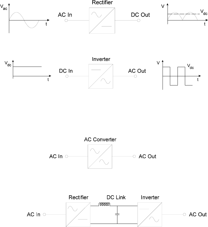
The following graphic symbols are used to designate the different types of converter.
• Rectifier is that special type of converter that converts AC to DC
• Inverter is that special type of converter that converts DC to AC.
• AC converter is that special type of converter that converts AC, of one
voltage and frequency, to AC of another voltage and frequency, which are
often variable.
An AC frequency converter is a special type of AC converter.
In a power electronic AC converter, it is common to use an intermediary DC
link with some form of smoothing.
• DC converter is one that converts DC of one voltage to DC of another
voltage.
70 Practical Variable Speed Drives and Power Electronics
In a DC converter, it is common to use an intermediary AC link, usually with
galvanic isolation via a transformer.
• Electronic switch is one that electronically connects or disconnects an AC or
DC circuit and can usually be switched ON and/or OFF. Conduction is
usually permitted in one direction only.
The following components are those devices that are most commonly used as electronic
switches in power electronic converters. Developments in semiconductor technology
have made these power electronic components smaller, more reliable, more efficient
(lower losses), cheaper and able to operate at much higher voltages, currents and
frequencies. The idealised operating principles of these components can be described in
terms of simple mathematical expressions.
• Power diodes
• Power thyristors
• Gate turn-off thyristors (GTO)
• MOS controlled thyristors (MCT)
• Power bipolar junction transistors (BJT)
• Field effect transistors (FET, MOSFET)
• Integrated gate bipolar transistors (IGBT)
• Resistors (provide resistance)
• Reactors or chokes (provide inductance)
• Capacitors (provide capacitance)
In power electronic circuits, semiconductor devices are usually operated in the bi-stable
mode, which means that they are operated in either one of two stable conditions:
• Blocking mode: fully switched OFF
− Voltage across the component is high
− Current through the component is low (only leakage current)
Power electronic converters 71
• Conducting Mode: fully switched ON
− Voltage across the component is low
− Current through the component is high
Diodes and thyristors are inherently bi-stable but transistors are not. Transistors must be
biased fully ON to behave like bi-stable devices.
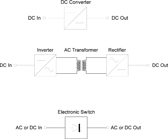
3.3 Power diodes
A power diode is 2-terminal semiconductor device with a relatively large single P-N
junction. It consists of a 2-layer silicon wafer attached to a substantial copper base. The
base acts as a heat-sink, a support for the enclosure and also one of the electrical
terminals of the diode. The other surface of the wafer is connected to the other electrical
terminal. The enclosure seals the silicon wafer from the atmosphere and provides
adequate insulation between the two terminals of the diode. The two terminals of a diode
are called the anode (A) and the cathode (K). These names are derived from the days
when Valves were commonly used.
SYMBOL:
IDEAL:
Forward conduction: Resistanceless
Reverse blocking: Lossless
Switch on/off time: Instantaneous
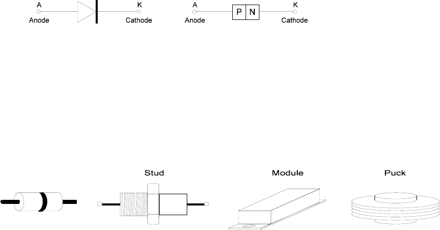
Many different mechanical designs are commonly used for diodes, some of which are
shown below. Power diodes rated from a few amperes are usually stud mounted but it is
increasingly common (more economical) to have several diodes encapsulated into an
insulated module. Examples are full wave rectifiers, 6-pulse diode bridges, etc.
Figure 3.1:
Typical mechanical construction of diodes
The base of this type of diode module is usually not electrically active, so it can be
mounted directly onto the heat-sink of a converter. Larger units for high current ratings
are usually of the disc type, which provides a larger area of contact between the case and
the heat-sink for better cooling.
When the anode is positive relative to the cathode, it is said to be forward biased and
the diode conducts current. When the anode is negative relative to the cathode the diode
is said to be reverse biased and the flow of current is blocked. The typical characteristic
of a power diode is shown in the figure below.
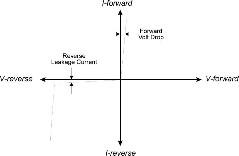
72 Practical Variable Speed Drives and Power Electronics
Figure 3.2:
Typical characteristic of a power diode
Unfortunately, power diodes have several limitations:
• In the conduction mode, when the diode is forward biased
− Real diodes are not resistanceless and there is a forward volt drop of
between 0.5 to 1.0 volts during conduction
− As a result, there is a limit to how much current can continuously flow
without overheating. This is the maximum rated current of the diode.
• In the blocking mode, when the diode is reverse biased
− there is a small leakage current
− there is a limit to how much voltage it can withstand before reverse
breakdown and current can start to flow in the reverse direction. It is
sound common practice to select diodes with a reverse voltage limit of
at least twice the value that will practically occur.
• The commutation time from the blocking mode to the conduction mode and
vice versa takes a finite time.
A power diode must be rated for the electrical environment in which it is to be used.
The following are the most important factors that must be considered when choosing a
power diode for a converter application:
• Forward current rating. The current rating is based on a certain wave shape
and should be taken as a guide only. The real selection should be based on the
total power losses in the diode taking into account the actual wave shape, load
cycle and cooling conditions.
Power electronic converters 73
• Forward voltage drop. This has an effect on current sharing between parallel
circuits that include diodes.
• Forward surge current capability (rate of rise of current di/dt)
• Reverse voltage rating (sometimes referred to as PIV - peak inverse voltage)
• Reverse recovery current di/dt. This should be taken into account when
considering the commutation transients in the diode circuit.
• I
2
t rating. This is a measure of the energy that a diode can handle in the case
of a short circuit without permanent damage. It gives a guide to the correct
choice of high speed fuses to protect the diode. Briefly, a protection fuse must
be chosen with an I
2
t rating lower than the diode.
Depending on the application requirements, various types of diode are available:
• Schottky diodes
• These diodes are used where a low forward voltage drop, typically 0.4 volts, is
needed for low output voltage circuits. These diodes have a limited blocking
voltage capability of 50 to 100 volts.
• Fast recovery diodes
• These diodes are designed for use in circuits where fast recovery times are
needed, for example in combination with controllable switches in high
frequency circuits. Such diodes have a recovery time (t
RR
) of less than a few
microsecs.
• Line frequency diodes
• The on-state voltage of these diodes is designed to be as low as possible to
ensure that they switch on quickly in rectifier bridge applications. Unfortunately
the recovery time (t
RR
) is fairly long, but this is acceptable for line-frequency
rectifier applications. These diodes are available with blocking voltage ratings
of several kV and current ratings of several hundred kamps. In addition, they an
be connected in series or parallel to satisfy high voltage or current requirements.
3.4 Power thyristors
Thyristors are often referred to as SCRs (silicon controlled rectifiers). This was the name
originally given to the device when it was invented by General Electric (USA) in about
1957. This name has never been universally accepted and used. The name accepted by
both the IEC and ANSI/IEEE is reverse blocking triode thyristor or simply thyristor. The
name thyristor is a generic term that is applied to a family of semiconductor devices that
have the regenerative switching characteristics. There are many devices in the thyristor
family including the power thyristor, the gate turn-off thyristor (GTO), the field
controlled thyristor (FCT), the triac, etc.
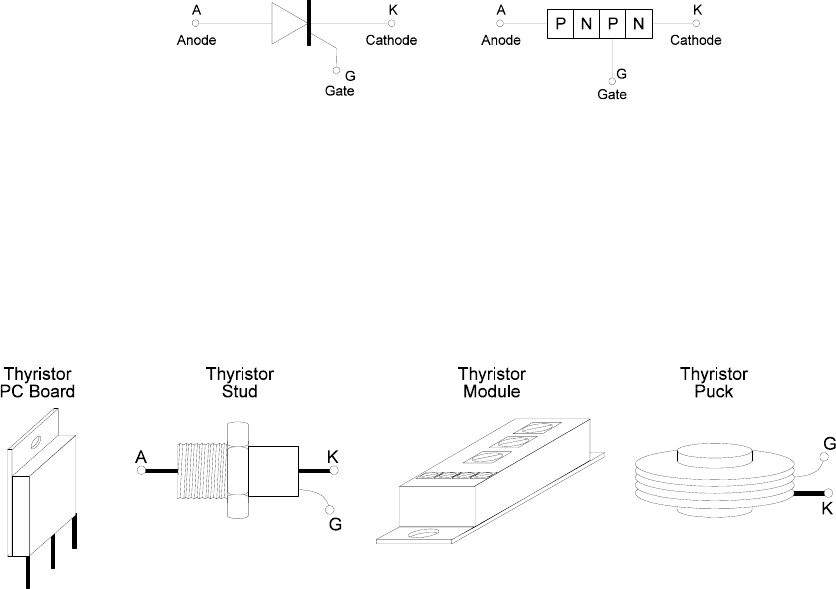
A thyristor consists of a 4-layer silicon wafer with 3 P-N junctions. It has two power
terminals, called the anode (A) and cathode (K), and a third control terminal called the
gate (G). High voltage, high power thyristors sometimes also have a 4th terminal, called
an auxiliary cathode and used for connection to the triggering circuit. This prevents the
main circuit from interfering with the gate circuit.
A thyristor is very similar to a power diode in both physical appearance and
construction, except for the gate terminal required to trigger the thyristor into the
conduction mode.
74 Practical Variable Speed Drives and Power Electronics
SYMBOL:
IDEAL: Forward conduction: Resistanceless
Forward blocking: Lossless (no leakage current)
Reverse blocking: Lossless (no leakage current)
Switch on/off time: Instantaneous
As with power diodes, smaller units are usually of the stud type but it is also
increasingly common to have 2 or more thyristors assembled into a thyristor module. The
base of this type of pack is not electrically active, so it can be mounted directly onto the
heat-sink of a converter. Large thyristor units are usually of the disc type for better
cooling.
Figure 3.3:
Typical mechanical construction of thyristors
Most converters for the speed control of motors are air-cooled, the smaller units using
natural convectional cooling over the heat-sink and the larger units using a fan for forced
cooling.
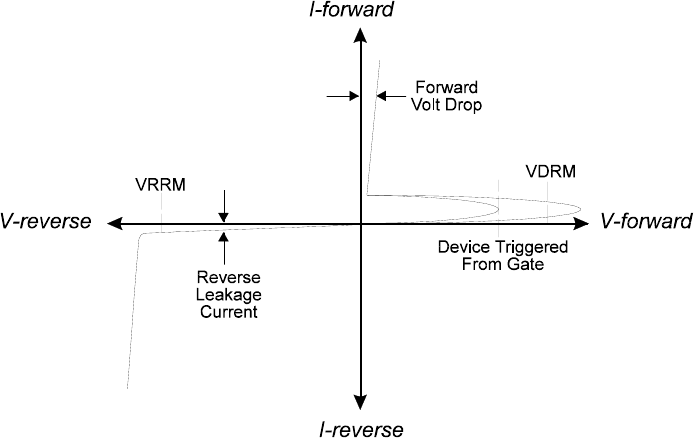
A thyristor is a controllable device, which can be switched from a blocking state (high
voltage, low current) to a conducting state (low voltage, high current) by a suitable gate
pulse. Forward conduction is blocked until an external positive pulse is applied to the gate
terminal. A thyristor cannot be turned off from the gate. During forward conduction, its
behavior resembles that of a power diode and it also exhibits a forward voltage drop of
between 1 to 3 volts. Like the diode, conduction is blocked in the reverse biased
direction. A typical characteristic of the thyristor is shown in the Figure 3.4.
There are several ways in which a thyristor can be turned on or brought into forward
conduction.
• Positive current gate pulse. This is the normal way that a thyristor is brought
into conduction. The gate pulse must be of a suitable amplitude and duration,
depending on the size of the thyristor.
• High forward voltage. An excessively high forward voltage between the
anode and the cathode can cause enough leakage current to flow to trigger the
turn on process.
• High rate of rise of forward voltage, dV/dt. A high dV/dt can produce
enough leakage current to trigger the turn on process.
Power electronic converters 75
• Excessive temperature. The leakage current increases with temperature, so
high temperature can aggravate the above two problems.
Figure 3.4:
Typical characteristic of a thyristor
A thyristor must be suitable for the electrical environment in which it is used. The
following are some of the more important factors which must be considered when
choosing a thyristor for a converter application:
• Same factors outlined above for diodes.
• The power losses in the thyristor comprise the conduction losses, switching
losses (turn on and turn off), gate power losses, forward off state losses and
reverse blocking losses. The data sheet usually provides curves for estimating
power losses for various wave shapes.
• Peak forward voltage (PFV). This is the forward anode voltage that the
device must withstand without switching on and without damage.
• Rate of rise of forward voltage dV/dt should not be too high, typically it
should be less than about 200 Volt/µsec. A parallel RC snubber circuit is
usually required to protect the thyristor.
• Rate of rise of anode current di/dt should not be too high, typically it should
be less than about 100 amp/µsec. The current is initially concentrated around
the gate and takes a finite time to spread over the conducting area.
If the rate of rise is too high, local overheating could damage the thyristor. Circuit
inductance is usually required to limit the rate of rise of current.
• Holding current. The minimum forward current required for the thyristor to
maintain forward conduction.
• Latching current. The minimum forward current that causes the thyristor to
initially latch. This is usually higher than the holding current and is important
because the gate pulse may be relatively short.
76 Practical Variable Speed Drives and Power Electronics
• Gate triggering requirements. A relatively small gate pulse will turn the
thyristor on. Typically a value of 100 mA for 10 µsec is the threshold. In
practice, a much higher value should be used for optimum thyristor operation.
Also, the turn on time is affected by the magnitude of the gate pulse.
The thyristor is turned off when it becomes reverse biased and/or the forward current
falls below the holding current. This must be controlled externally in the power circuit.
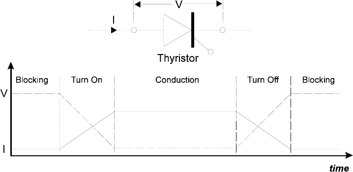
3.5 Commutation
The transitional period from blocking to conducting, and vice versa, is called
commutation and the period during which a component turns on/off, is called the
commutation period. During commutation, the component comes under electrical stress
due to changes in the circuit conditions and the thermal stress due to losses. These losses
produce heat in the component and also stress the insulation and current paths.
• In the blocking mode, losses are usually small and mainly due to the leakage
current flowing through the device
• In the conducting mode, losses are relatively higher and mainly due to the
current and forward volt drop across the component (I
2
R losses)
• During commutation, losses are due to the transitional voltage and current
activity within the component and in the control circuit to trigger the gate.
Figure 3.5 illustrates thyristor commutation for both the turn-on and the turn-off
periods.
Figure 3.5:
Simple commutation of an electronic switch
In modern PWM inverters, there is a tendency to use electronic switches operating at
high switching frequencies to achieve faster responses or better output wave-shapes.
Unfortunately, the increased number of commutations results in higher losses both in the
triggering circuits as well as the power circuits of the components.
Losses may be reduced by using devices that have the following characteristics:
• Low leakage current during blocking
Power electronic converters 77
• Low forward volt drop during conduction
• High switching speed, short commutation period
• Low triggering losses in the control circuit
3.6 Power electronic rectifiers (AC/DC converters)
The first stage of an AC frequency converter is the conversion of a 3-phase AC power
supply to a smooth DC voltage and current. Simple bi-stable devices, such as the diode
and thyristor, can effectively be used for this purpose.
Initially, when analyzing power electronic circuits, it will be assumed that the bi-stable
semiconductor devices, such as the diodes and thyristors, are ideal switches with no
losses and minimal forward voltage drop. It will also be assumed that the reactors,
capacitors, resistors, and other components of the circuits have ideal linear characteristics
with no losses. Once the operation of a circuit is understood, the imperfections associated
with the practical components can be introduced to modify the performance of the power
electronic circuit.
In power electronics, the operation of any converter is dependent on the switches being
turned ON and OFF in a sequence. Current passes through a switch when it is ON and is
blocked when it is OFF. As mentioned above, the word commutation is used to describe
the transfer of current from one switch turning OFF to another turning ON.
In a diode rectifier circuit, a diode turns ON and starts to conduct current when there is
a forward voltage across it, i.e. the forward voltage across it becomes positive. This
process usually results in the forward voltage across another diode becoming negative,
which then turns off which stops conducting current. In a thyristor rectifier circuit, the
switches additionally need a gate signal to turn them on and off.
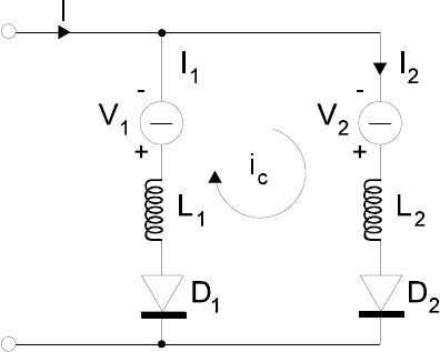
Figure 3.6:
Simple circuit to illustrate commutation from diode D1 to D2
The factors affecting commutation may be illustrated in the idealized diode circuit in
Figure 3.6, which shows two circuit branches, each with its own variable DC voltage
source and circuit inductance. Assume, initially, that a current I is flowing through the
circuit and that the magnitude of the voltage V
1
is larger than V
2
. Since V
1
> V
2
, diode D1
has a positive forward voltage across it and it conducts a current I
1
through its circuit
inductance L
1
. Diode D
2
has a negative forward voltage across it and is blocking and
carries no current.

78 Practical Variable Speed Drives and Power Electronics
Consequently, at time t
1
I
1
= I
I
2
= 0
Suppose that voltage V
2
is increased to a value larger than V
1
, the forward voltage
across diode D
2
becomes positive and it then starts to turn on. However, the circuit
inductance L
1
prevents the current I
1
from changing instantaneously and diode D
1
will not
immediately turn off. So, both diodes D
1
and D
2
remain ON for an overlap period called
the commutation time t
c
.
With both diodes turned on, a closed circuit is established which involves both
branches. The effective circuit voltage V
C
= (V
2
– V
1
), called the commutation voltage,
then drives a circulating current i
c
, called the commutation current, through the two
branches which have a total circuit inductance of L
C
= (L
1
+ L
2
).
In this idealized circuit, the volt drop across the diodes and the circuit resistance have
been ignored. From basic electrical theory of inductive circuits, the current i
c
increases
with time at a rate dependent on the circuit inductance. The magnitude of the
commutation current may be calculated from the following equations.
t
i
)
L
+
L
( = )
V
V
(
d
d
c
21
12
−
t
i
L
=
V
d
d
c
c
c
L
V
=
t
i
c
cc
d
d
If the commutation starts at a time t
1
and finishes at a time t
2
, the magnitude of the
commutation current I
C
at any time t, during the commutation period, may be calculated
by integrating the above equation from time t
1
to t.
t
V
L
=
I
d
1
c
c
c
∫
During the commutation period:
• It is assumed that the overall current through the circuit remains constant.
I = (I
1
+I
2
) constant
As the circulating commutation current increases:
• Current (I
2
) through the diode that is turning on increases in value
I
2
= I
c
increasing