Massoud M. Engineering Thermofluids: Thermodynamics, Fluid Mechanics, and Heat Transfer
Подождите немного. Документ загружается.


IIIc. Fluid Mechanics: Compressible Flow
412
the extent of the control volume is from inlet (1) through the throat (2). We make
the following simplifying assumptions: the fluid behaves as an ideal gas, the flow
velocity is less than the speed of sound in the fluid, and the process is steady as
well as isentropic. The energy equation between stages 1 and 2,
2
11
/2hV+=
2
22
/2hV+
, can be written as:
)(2
11
12
2
2
2
2
2
2
1
2
1
TTcm
AA
p
−=
¸
¸
¹
·
¨
¨
©
§
−
ρρ
where we substituted for velocities from the continuity equation,
11 1
mVA
ρ
==
22 2
VA
ρ
. Also substituting for temperature in terms of pressure from the isentropic
relation IIa.4.3 (i.e.,
12
/
ρρ
= (P
1
/P
2
)
1/
γ
), for c
p
from c
p
= R
γ
/(
γ
–1), and for density
from
/
P
RT
ρ
= and after some algebraic manipulation, we find:
()
»
»
¼
º
«
«
¬
ª
−
−
¸
¸
¹
·
¨
¨
©
§
−
=
−
γ
γγγ
β
ρ
γ
γ
/24
/)1(/2
112
1
1
1
2
r
rr
PAm
where A
2
is the flow area at the throat,
12
/ DD=
β
, and
12
/ PPr = . Using the
same argument as in Section IIIb.4.2 for incompressible flow measurement by
Bernoulli obstruction meters, the above relation becomes:
()
»
»
¼
º
«
«
¬
ª
−
−
¸
¸
¹
·
¨
¨
©
§
−
=
−
γ
γγγ
β
ρ
γ
γ
/24
/)1(/2
112
1
1
1
2
r
rr
PACm
d
IIIc.1.36
Comparing Equation IIIc.1.36 with relation IIIb.4.4, we seek a means to express
the flow rate of both compressible and incompressible fluids with an identical re-
lation. To do so, we define a factor Y (referred to as the adiabatic expansion fac-
tor or net expansion factor):
flowibleincompressanofrateflowmass
flowlecompressibaofrateflowmass
=Y
Substituting for the numerator from Equation IIIc.1.36 and for the denominator
from Equation IIIb.4.4 yields:
PYAm ∆=
12
2
ρα
IIIc.1.37
where A
2
is the venturi throat diameter,
4
1/
βα
−=
d
C ,
12
/ DD=
β
, ∆P = P
1
– P
2
, and Y is given as:
()
2/ ( 1)/
4
42/
1
11 1
Venturi
rr
Y
rr
γγγ
γ
γβ
γβ
+
−
−
=
−− −
IIIc.1.38

1. Steady Internal Compressible Viscous Flow
413
Knowing the type of gas (γ) and the inlet pressure and temperature, we know the
gas density (
ρ
). If we also know the throat pressure (P
2
and alternatively r =
P
2
/P
1
) and the venturi size (
β
), we can calculate Y from Equation IIIc.1.38 and
then find mass flow rate from Equation IIIc.1.37. Since the calculation of Y is la-
borious, values of Y have been provided in tables and figures for various gases (
γ)
and venturi sizes
β
. The expansion coefficient as calculated above applies to noz-
zles and venturies. ASME has provided the following correlation for a thin-plate
orifice:
]/)1)[(35.041.0(1
4
γβ
rY
Orifice
−+−= IIIc.1.39
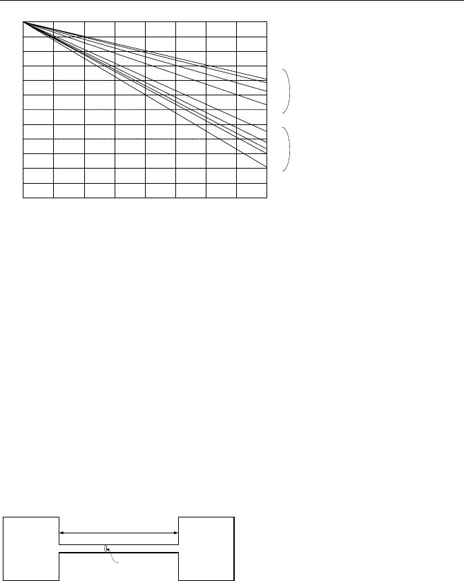
Values for the adiabatic expansion factor as given by Equations IIIc.1.38 and
IIIc.1.39 are plotted in Figure IIIc.1.5. Note that the differential pressure taps are
located one-pipe diameter upstream and a half-pipe diameter downstream of the
inlet face of the nozzle and the orifice plate (D:D/2).
Example IIIc.1.6. A venturi meter is used to measure the flow of carbon dioxide.
The inlet and the throat diameters are 5 (12.7 cm) and 2 (5.08 cm) inches, respec-
tively. Inlet pressure and temperature are 150 psia (1.034 MPa) and 200 F
(93.33 C). Pressure at the throat of the venturi is 145 psia (1 MPa). Carbon diox-
ide kinematic viscosity is 1.32E-5 ft
2
/s (1.23E-6 m
2
/s) and for carbon dioxide,
γ
= 1.3. Find the mass flow rate.
Solution: To use Equation IIIc.1.37, we need to find A,
ρ
, r, and Y:
2
22
/4AD
π
==
π
(2/12)
2
/4 = 0.0218 ft
2
(2 cm
2
)
932.0)]200460()44/1545/[(144150/
111
=+××== RTP
ρ
lbm/ft
3
(14.93 kg/m
3
)
Having
γ
= 1.3,
β
= 2/5 = 0.4 and r = P
2
/P
1
= 145/150 = 0.967, we find Y:
()
98.0
967.01
4.01
967.0.40-1
967.0967.0
3.0
1.3
4
3.1/24
3.1/3.23.1/2
=
−
−
×
−
=
Venturi
Y
The discharge coefficient is found from Equation IIIb.4.7 as:
4.5
0.9858 0.196
d
C
β
=− = 0.983
The flow coefficient becomes
4
/1
d
C
α
β
=− = 0.983/(1 – 0.4
4
)
0.5
= 0.995. Fi-
nally, mass flow rate from Equation IIIc.1.37 is found as:
419.4)1445(932.02.3220218.098.0995.02
12
=××××××=∆= PYAm
ρα
lbm/s
(2 kg/s)
IIIc. Fluid Mechanics: Compressible Flow
414
0.00
0.02
0.04
0.06
0.08
0.10
0.12
0.14
0.16
0.8
0.9
1.0
0.95
0.85
0.7
0.5
0.3
0.0
β
2
0.5
0.4
0.3
0.0
0.2
(1-r)/
γ
Y
Nozzles
and
Venturies
Orifices
Figure IIIc.1.5. Values of the net expansion factor Y for Bernoulli obstruction meters
2. The Phenomenon of Choked or Critical Flow
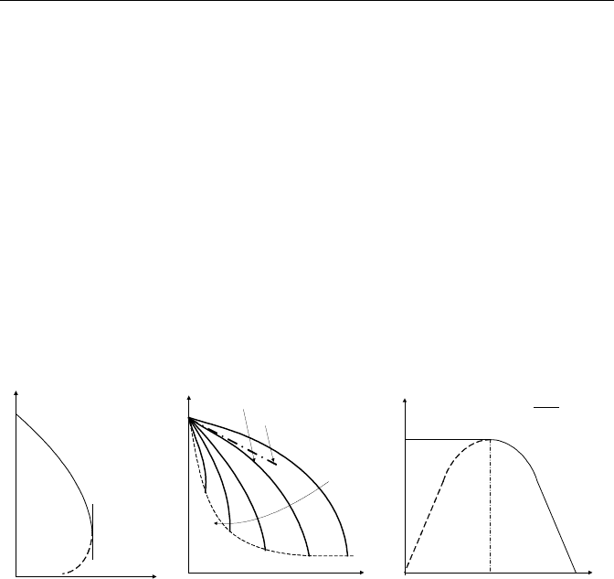
In the flow of fluids, any downstream perturbation travels upstream at the speed of
sound in that fluid. We now consider two tanks connected by a pipe as shown in
Figure IIIc.2.1. The tanks are filled with a compressible fluid and are initially at
the same thermodynamic condition. Hence, there is no flow of fluid from the left
tank to the right tank and vice versa. If we maintain pressure in the left tank and
begin to reduce pressure in the right tank, a flow rate will be established. The
more we reduce pressure in the right tank the higher the rate of flow will be be-
tween the two tanks. As was discussed in Section IIIb.7, this is due to the fact that
reduction in the downstream pressure, being a disturbance, is carried upstream
faster than the flow velocity. Once this reduction in pressure is “felt” upstream,
the rate of flow increases.
P
o
P
b
L
D
Figure IIIc.2.1. Tanks filled with compressible fluid and connected by a pipe.
There is of course a limit to the increase in the flow rate. This limit is reached
when the flow velocity itself reaches the speed of sound. In this case, the speed of
the disturbance to travel upstream is the same as the flow velocity. Hence, the
perturbation cannot be “communicated” upstream. As a result, the flow rate re-
mains the same regardless of further reduction in the downstream pressure. Flow
rate under such circumstance is choked. The choked or critical flow rate is, there-
fore, only a function of the upstream pressure in the flow field. For ideal gases,
2. The Phenomenon of Choked or Critical Flow
415
we can derive an analytical relation for the choked flow rate. For non-ideal fluids,
we have to resort to hybrid solutions, being a blend of theory and experimental
data in the form of a correlation. In this chapter, we are concerned only with the
choked flow of single-phase compressible fluids such as ideal gases, saturated,
and superheated steam. Choked flow for two-phase (water and steam) conditions
is discussed in Chapter Va.
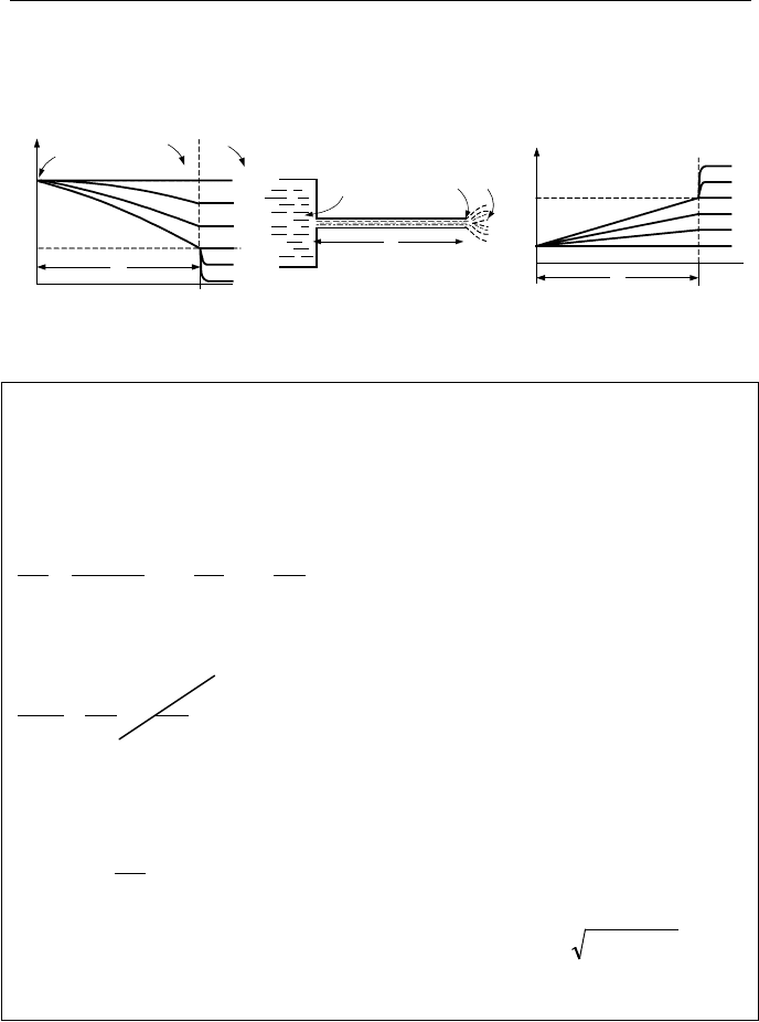
Assuming the process is isothermal, we examine Equation IIIc.1.16. As shown
in Figure IIIc.2.2(a), the ratio of P/
ρ
V
2
determines the slope, dP/dx. For P/
ρ
V
2
> 1,
the slope is negative. This is the region on the curve between points A and B. For
P/
ρ
V
2
< 1, the slope is positive. This is the region between points B and C. For
P/
ρ
V
2
= 1, which occurs at point B, the tangent to the curve is vertical. The condi-
tion corresponding to point B is called the critical condition and the pressure at
point B, the critical pressure. Let’s now examine Equation IIIc.1.19. Figure
IIIc.2.1(b) shows the plot of P
b
/P
o
versus fL/D for various Mach numbers. The
straight line represents the incompressible flow behavior from Equation IIIc.1.20.
x
P
A
B
C
f L/D
A
B
B
B
BB
Ma
0
0
1
0.1
0.125
0.2
Compressible
Incompressible
r
r
m
m
.
.
*
r0
*
1
r
P
b
P
o
=
(a) (b) (c)
Figure IIIc.2.2. (a) and (b) Depiction of Equation IIIc.1.16 and (c) Equation IIIc.1.19
Note in Figure IIIc.2.2(b) similar to Figure IIIc.2.2(a), as flow velocity ap-
proaches the speed of sound in the fluid, the denominator approaches zero. At
sonic velocity, the tangent to the curve becomes vertical. Finally, in examining
Equation IIIc.1.19, we obtain a parabolic plot of mass flow rate versus r = P
b
/P
o
as
shown in Figure IIIc-2-2(c). At r = 1 (P
b
= P
o
) there is no flow. As P
2
is lowered,
flow rate increases. As discussed above, there is a critical pressure (shown by
*
e
P
and the corresponding ratio by r
*
) beyond which the flow becomes independent of
the downstream pressure. Equation IIIc.1.31 shows that the mass flow rate peaks
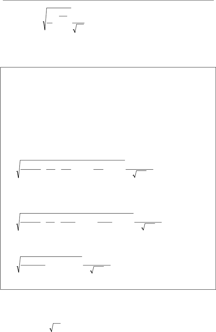
when the downstream pressure causes flow to become sonic. El-Wakil has sum-
marized the above discussion in the plots of Figure IIIc.2.3. As shown in this Fig-
ure IIIc.2.3, when the source pressure is equal to the downstream, back, or the re-
ceiving tank pressure, there is no flow and velocity is zero (line number 0). Line
numbers 1 and 2 show subsonic flow, which increases with further reduction in
IIIc. Fluid Mechanics: Compressible Flow
416
back pressure. Line 3 shows the back pressure at which flow has become sonic.
Lines 4 and 5 show that further reduction in back pressure beyond that of line 3
does not result in further flow increase.
P
1
3
5
0
2
4
P
o
P
b
L
0
1
2
3
4
5
P
e
P
e
*
L
P
o
P
e
P
b
V
V*
L
4
2
0
5
3
1
0
1
2
3
4
5
Figure IIIc.2.3. Pressure and Flow Velocity of Compressible Fluids (El-Wakil)
Example IIIc.2.1. Show that for an isentropic condition the critical flow of a
compressible fluid in a horizontal constant area pipe is identical to the mass flow
rate at sonic speed.
Solution: For choked flow 0/ =dPmd
. We find from the continuity equation
under steady state condition:
0
)(
=+==
d
P
dV
A
d
P
d
VA
d
P
VAd
d
P
md
ρ
ρ
ρ
from which we find dP/dV = (–
ρ
/V)dP/d
ρ
. From Equation IIIc.1.4 for frictionless
flow:
0
2
2
=++
D
dx
f
V
dV
V
dP
ρ
from which we find dP/dV = –
ρ
V. Therefore, (–
ρ
/V)dP/d
ρ
= –
ρ
V. Since G =
ρ
V,
then:
()
2222
c
d
dP
G
s
ρ
ρ
ρ
=
¸
¸
¹
·
¨
¨
©
§
=
where we substituted for the speed of sound as given by
s
ddPc )/(
ρ
= . Note
that subscript s, for entropy, is added to emphasize that the process is adiabatic
and frictionless (isentropic).
2.1. Calculation of Choked Flow for Ideal Gases
We can readily derive the flow rate of ideal gases under choked condition from the
energy equation written between the flow upstream and the receiving tank down-
stream as:

2. The Phenomenon of Choked or Critical Flow
417
h
o
= h
b
+
2
b
V /2 IIIc.2.1
where the stagnation enthalpy (i.e., the enthalpy plus the associated kinetic en-
ergy) is used for the upstream flow. Substituting for enthalpies, we find:
2
b
V = 2c
p
T
b
(T
o
/T
b
– 1) IIIc.2.2
Relating velocity to Mach number via Ma
2
= V
2
/c
2
and substituting for c
2
=
γ
RT,
we obtain:
)1/(
1
2
)1/)](1/([2
)1/(2)1/(2
Ma
2
−
−
=
−−
=
−
=
−
=
bo
bo
bop
b
bop
TT
R
TTR
R
TTc
RT
TTTc
γγ
γγ
γγ
so that
2
Ma1/
ζ
+=
bo
TT IIIc.2.3
where
ζ
= (
γ
– 1)/2. Using the isentropic relations given by Equations IIa.4.4
and IIa.4.5, we further find that:
()
)1/(
2
Ma1/
−
+=
γγ
ζ
bo
PP IIIc.2.4
()
)1/(1
2
Ma1/
−
+=
γ
ζρρ
bo
IIIc.2.5
It is important to note that when flow is choked, Ma = 1, hence
T*/T
o
= Ȝ IIIc.2.6
ρ
*/
ρ
o
= Ȝ
1/(
γ
– 1)
IIIc.2.7
P*/P
o
= Ȝ
γ
/(
γ
– 1)
IIIc.2.8
where Ȝ = 2/(
γ
+ 1) and * represents properties at the choked condition. From the
last relation we can identify two cases. First, back pressure less than critical pres-
sure, P
b
> P* and second, back pressure greater than critical pressure, P
b
< P*.
These cases are discussed next.
Case A. P
b
> P*
We can find mass flux from Equation IIIc.2.2 by substituting from T
b
/T
o
=
(P
b
/P
o
)
(
γ
– 1)/
γ
and
ρ
b
= P
b
/RT
b
= (P
o
/RT
o
)(P
b
/P
o
)
1/
γ
to obtain:
»
»
¼
º
«
«
¬
ª
¸
¸
¹
·
¨
¨
©
§
−
¸
¸
¹
·
¨
¨
©
§
−
==
+
γγγ
γ
γ
/)1(/2
1
2
/
o
b
o
b
o
o
P
P
P
P
RT
PAmG
IIIc.2.9
Case B. P
b
≤ P*
We can find mass flux from
VAmG
ρ
== /
with V and
ρ
substituted from Equa-
tions IIIc.2.2, IIIc.2.6, and IIIc.2.7, respectively to obtain:
IIIc. Fluid Mechanics: Compressible Flow
418
o
o
T
P
R
AmG
¸
¸
¹
·
¨
¨
©
§
−
+
==
1
1
/
γ
γ
λ
γ
IIIc.2.10
Expectedly, when flow is choked, P
b
does not appear in the equation for mass
flux.
Example IIIc.2.2. A tank contains air at stagnation properties of 100 psia (0.69
MPa) and 75 F (23.89 C). A 1 inch (2.54 cm) diameter vent valve is opened. Find
a) air flow rate if P
b
= 60 psia (0.36 MPa) and b) air flow rate if P
b
= 14.7 psia
(1 atm).
Solution: For Air,
γ
= c
p
/c
v
= 0.24/0.17 = 1.4 hence Ȝ = 2/(1 + 1.4) = 0.8334.
Also R = R
u
/M
air
= 1545/28.97 = 53.33 ft lbf/lbm R (0.287 kJ/kmol·K), T
o
= 75 +
460 = 535 R (297 K), and A = 5.454E-3 ft
2
(5.07E-4 m
2
). We first find P*, the
pressure at which flow is choked. This is found from Equation IIIc.2.8 as:
P* = P
o
λ
γ
/(
γ
– 1)
= 100(0.8334)
1.4/0.4
= 52.83 psia (0.36 MPa)
a) Since P
b
> P*, we use Equation IIIc.2.9:
()
2.320
535
144100
)
100
65
()
100
65
(
4.0
4.1
33.53
2.322
4.1/4.24.1/2
=
×
¸
¹
·
¨
©
§
−×
×
=G lbm/s·ft
2
(1612.2 kg/s·m
2
)
Therefore, lbm/s745.13E454.52.320 =−×=m
(0.79 kg/s)
b) We can find the choked flow rate from either Equation IIIc.2.9:
()
24.331
535
144100
)
100
83.52
()
100
83.52
(
4.0
4.1
33.53
2.322
4.1/4.24.1/2
=
×
¸
¹
·
¨
©
§
−×
×
=G
lbm/s·ft
2
(1617.24 kg/s·m
2
)
or from Equation IIIc.2.10:
()
24.331
535
144100
)8334.0(
33.53
2.324.1
4./4.2
=
××
=G lbm/s·ft
2
(1617.24 kg/s·m
2
)
The choked mass flow rate is lbm/s81.13E454.524.331 =−×=m
(0.821 kg/s).
To expedite arithmetic, we may calculate the constants in Equation IIIc.2.10
for a specified ideal gas. If for example air is the working fluid, then the choked
mass flux of air in British Units becomes:
ooBU
TPG /63.76= IIIc.2.11-1

2. The Phenomenon of Choked or Critical Flow
419
where P
o
is the source pressure in psia, T
o
is the source temperature in degree
Rankine, and G is mass flux in lbm/s·ft
2
. Similarly, for P
o
in kPa and T
o
in degree
Kelvin, mass flux of air in kg/s·m
2
is given by:
ooSI
TPG /42.40= IIIc.2.11-2
Example IIIc.2.3. Air in an isentropic process and at a rate of 5 kg/s is expanded
through the throat to an exit Mach number of 2. The air pressure and temperature
at the inlet are P
o
= 350 kPa and T
o
= 250 C (523 K). Find a) the throat area, b)
the air pressure and temperature at the exit, c) exit velocity and exit area.
Solution: For Air,
γ
= c
p
/c
v
= 0.24/0.17 = 1.4,
ζ
= (γ – 1)/2 = 0.2, and Ȝ = 2/(1 +
γ
) = 2/(1 + 1.4) = 0.8334.
a) Since V
exit
> 1 then V
throat
= 1:
oo
TPG /42.40= = 40.42 × 350/(523)
0.5
= 618.6 kg/s·m
2
GmA
throat
/
= = 5/618.6 = 8.08E-3 m. Therefore,
D
throat
= (4A/
π
)
0.5
= (4 × 8.08E-3/
π
)
0.5
= 10 cm
b) We use Equations IIIc.2.3 and IIIc.2.4:
T
exit
= T
o
/[1 +
ζ
Ma
2
] = 523/[1 + 0.2 × 2
2
] = 290.5 K
P
exit
= P
o
/[1 +
ζ
Ma
2
]
γ
/(
γ
– 1)
= 350/[1 + 0.2 × 2
2
]
3.5
= 44.73 kPa
c) V
exit
= cMa and c = RT
γ
= [1.4 × (8,314/28.97) × 290.5]
0.5
= 339.58 m/s
To find A
exit
, we find
ρ
exit
having P
exit
and T
exit
:
ρ
exit
= P
exit
/(RT
exit
) = 44.73/[(8.314/28.97) × 290.5] = 0.536 kg/m
3
A
exit
= Vm
ρ
/(
) = 0.0274 m
2
.
Therefore, D
throat
= (4A/
π
)
0.5
= (4 × 0.0274/
π
)
0.5
= 18.7 cm
2.2. Steady Flow of Ideal Gases Through Pipe Breaks
The rate of discharging compressible fluids to the atmosphere depends generally
on the source and the sink pressures as well as the flow path length and diameter.
As shown in Figure IIIc.2.4, the flow path may be equipped with fittings and
valves and hence, the frictional losses due to skin friction and form losses in
valves and fittings must be accounted for in the analysis. As a result, the flow
may be either subsonic or choked.
It is therefore important to determine the flow condition prior to the calculation
of the flow rate, as discussed next.
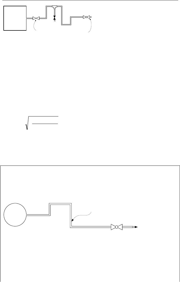
IIIc. Fluid Mechanics: Compressible Flow
420
P
1
Isolation
Valve
Regulating
Valve
P
2
Figure IIIc.2.4. Discharging compressible fluids to the atmosphere through valves and fit-
tings
A. Steady Flow of Ideal Gases Through Pipe Breaks, Subsonic Flow
To obtain the mass flow rate, we use Equation IIIb.3.14 as was derived for incom-
pressible fluids. To account for the changes in density due to the associated pres-
sure drop through the flow path, we find fluid density at the source pressure and
temperature (
ρ
1
) while introducing Y, the adiabatic expansion factor. Addition-
ally, as was discussed in the derivation of Equations IIIb.4.4 and IIIc.1.37, to ac-
count for the deviation from ideal conditions, we apply
α
, the flow coefficient.
Therefore, mass flow for compressible fluids (Equation IIIb.3.14) becomes:
K
)(
2
211
PP
YAm
−
=
ρ
IIIc.2.12
where
i
DfL
¦
+= K/K . Equation IIIc.2.12 applies if flow remains subsonic.
The Y factor is given in Figure IIIc.2.5 for gases with
γ
= 1.3 and
γ
= 1.4. Flow
remains subsonic as long as we can find K from the plots of Figure IIIc.2.5. An
application of Equation IIIc.2.12 is discussed in the following example.
Example IIIc.2.4. Pressure in a large tank containing air is maintained at 50 psia
(0.34 MPa) and 120 F (49 C) while air is discharged to the atmosphere through a 1
in (2.54 cm) clean commercial steel pipe. The 50 ft (164 m) long pipe includes
four 90-degree elbows and a fully open globe valve. Find a) If flow is choked and
b) the mass flow rate of air.
1-inch Clean Commercial steel pipe
P = 50 psia
T = 120 F
Air
Solution: a) To see if flow is chocked, we need K and ∆P/P
1
:
K = [L/D + K
Entrnace
+ 4 × K
90-Elbow
+ K
Globe-Valve
+ K
Exit
]f
We find f = 0.023 from Table IIIb.3.2 and loss coefficients from Table IIIb.3.3:
K = [(50×12/1) + 0.5 + 4×30 + 340 + 1] × 0.023 = 24.4
∆P/P
1
= (50 – 14.7)/50 = 0.706
To find Y, we use Figure IIIc.2.5 to get; Y = 0.77

2. The Phenomenon of Choked or Critical Flow
421
Since we found Y from the figure, flow is not choked.
b) To find the mass flow rate from Equation IIIc.2.12, we need A and
ρ
:
A =
π
D
2
/4 =
π
(1/12)
2
/4 = 0.00545 ft
2
(5.063E-4 m
2
)
ρ
1
= P
1
/RT
1
= 50 × 144/[(1545/28.97) × (460 + 120)] = 0.233 lbm/ft
3
23.0]4.24/)1447.1414450(233.02.322[00545.077.0
5.0
=×−×××××=m
lbm/s.
B. Steady Flow of Ideal Gases Through Pipe Breaks, Choked Flow
The minimum value of Y corresponding to the maximum value of
∆P/P
1
is circled
on each plot in Figure IIIc.2.5 and tabulated next to the figure for a specified loss
coefficient K. If for a given gas (
γ
), given loss coefficient (K), and given ∆P/P
1
,
we cannot find the corresponding Y factor from Figure IIIc.2.5, we should then use
the associated table next to these plots, as specified in CRANE. This would imply
that the flow is choked. In this case, the choked flow rate is found from:
K
2
max1
P
YAm
∆
=
ρ
IIIc.2.13
where
∆P
max
must be obtained from the tables associated with Figure IIIc.2.5.
Example IIIc.2.5. Use the same data as in Example IIIc.2.3 but for a tank pres-
sure of 450 psia (3.1 MPa). Find a) if flow is choked and b) the maximum mass
flow rate of air.
Solution: a) Having K, to see if flow is chocked we need ∆P/P
1
:
∆P/P
1
= (450 – 14.7)/450 = 0.967
We cannot find Y from Figure IIIc.2.4. Thus, Y must be found from the related ta-
ble adjacent to Figure IIIc.2.4. Using K = 24.5, we find Y = 0.71 by interpolation.
This implies that flow is choked. From the same table, maximum ∆P/P
1
by inter-
polation is found as 0.8487.
∆P = 0.8487 × 450 = 381.9 psia (2.633 MPa)
b) Having A, to find the mass flow rate from Equation IIIc.2.13, we need
ρ
:
ρ
1
= P
1
/RT
1
= 450 × 144/[(1545/28.97) × (460 + 120)] = 2.1 lbm/ft
3
(33.64 kg/m
3
)
m
= 1.2]4.24/)]1449.381()1.22.32[(200545.071.0 =×××× lbm/s.
Standard Condition: Due to the change of density in compressible fluids,
flow rate is either expressed as mass per unit time or the volumetric flow rate per
hour at standard condition (P
S
= 14.7 psi and T
S
= 60 F = 520 R). To express flow
rate in terms of standard condition, since the mass flow rates must remain the
same, we write
