Mattingly J.D., Heiser W.H., Pratt D.T. Aircraft Engine Design
Подождите немного. Документ загружается.

276 AIRCRAFT ENGINE DESIGN
U
m
V'
0.30
0.25
0.20
0.15
0.10
M~ R =0.9
M 2 =0.9 .... " ...
M 2 =1.1 --
0.05 .... I .... i .... i ....
60 65 70 75 80
a 2 C)
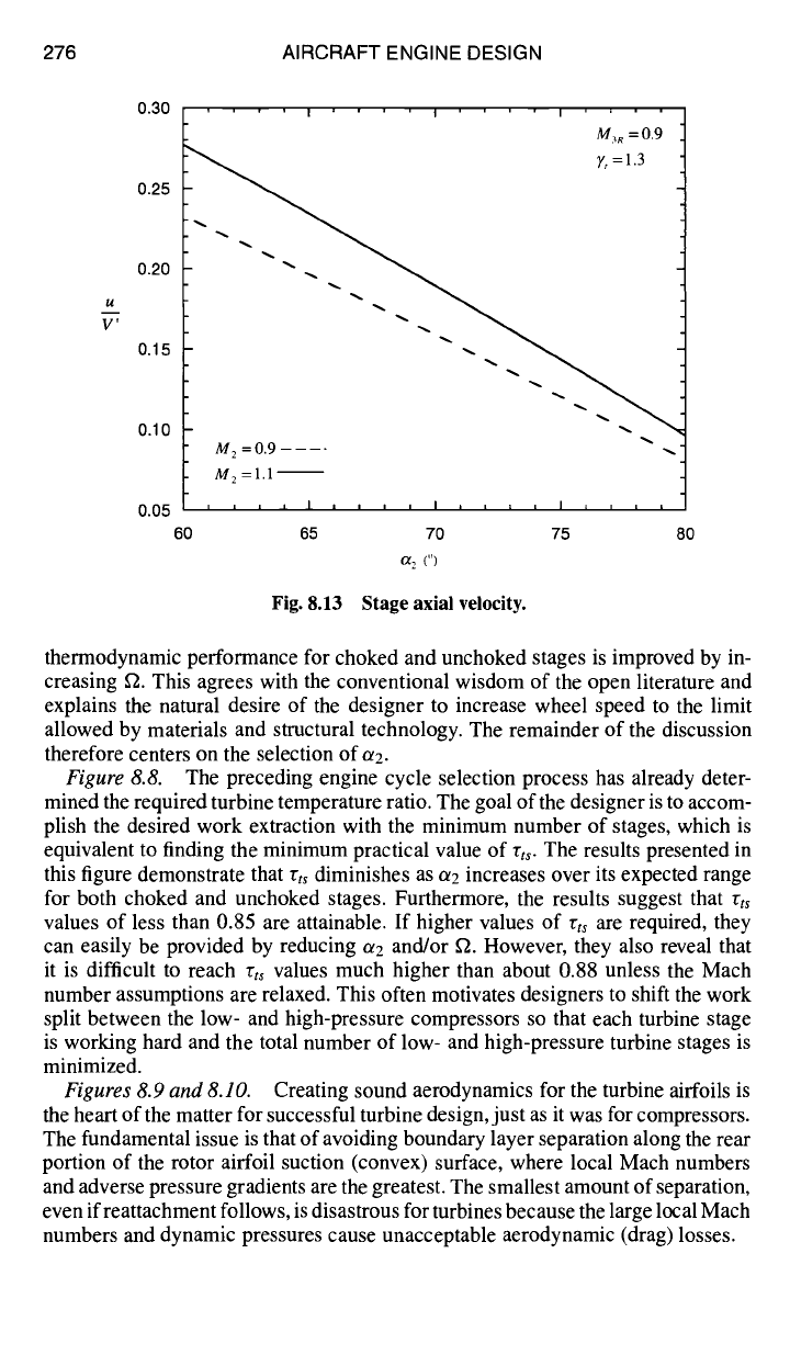
Fig. 8.13 Stage axial velocity.
thermodynamic performance for choked and unchoked stages is improved by in-
creasing f2. This agrees with the conventional wisdom of the open literature and
explains the natural desire of the designer to increase wheel speed to the limit
allowed by materials and structural technology. The remainder of the discussion
therefore centers on the selection of or2.
Figure 8.8. The preceding engine cycle selection process has already deter-
mined the required turbine temperature ratio. The goal of the designer is to accom-
plish the desired work extraction with the minimum number of stages, which is
equivalent to finding the minimum practical value of rts. The results presented in
this figure demonstrate that 75ts diminishes as or2 increases over its expected range
for both choked and unchoked stages. Furthermore, the results suggest that rts
values of less than 0.85 are attainable. If higher values of rts are required, they
can easily be provided by reducing ~2 and/or ~2. However, they also reveal that
it is difficult to reach rt~ values much higher than about 0.88 unless the Mach
number assumptions are relaxed. This often motivates designers to shift the work
split between the low- and high-pressure compressors so that each turbine stage
is working hard and the total number of low- and high-pressure turbine stages is
minimized.
Figures 8.9 and 8.10. Creating sound aerodynamics for the turbine airfoils is
the heart of the matter for successful turbine design, just as it was for compressors.
The fundamental issue is that of avoiding boundary layer separation along the rear
portion of the rotor airfoil suction (convex) surface, where local Mach numbers
and adverse pressure gradients are the greatest. The smallest amount of separation,
even if reattachment follows, is disastrous for turbines because the large local Mach
numbers and dynamic pressures cause unacceptable aerodynamic (drag) losses.
DESIGN: ROTATING TURBOMACHINERY 277
Unfortunately, as the results presented in Fig. 8.9 reveal, the tendency to in-
crease stage work extraction by increasing a2 is accompanied by a surprisingly
rapid increase in the rotor flow turning angle. The streamline curvature effects
within the passage between adjacent rotor airfoils caused by this flow turning are
the principal contributor to the low suction surface static pressures and therefore
to the potential for boundary layer separation, especially when the average Mach
number is near sonic and shock waves can arise. Carefully tailoring the pressure
distribution around the complete airfoil profile by means of sophisticated com-
putational fluid dynamics (CFD) in order to resist separation despite very large
rotor flow turning angles is one of the major achievements of modern turbine tech-
nology (see Ref. 1). However, because the CFD must account for such exquisite
effects as the state of the boundary layer (for example, laminar, turbulent, or tran-
sitional), freestream turbulence levels, airfoil roughness, airfoil heat transfer, and
locally transonic flow, the application of these methods is beyond the scope of this
textbook.
Instead, we will capitalize on our general observation that skillful designers are
able to define rotor airfoil profiles that do not separate for flow turning angles
(/32 +/33) up to 120-130 deg provided that the rotor degree of reaction is at least
0.20. That is, the average static temperature and pressure drop significantly across
the rotor in order to partially counteract the adverse pressure gradient due to stream-
line curvature. Combining the results of Figs. 8.9 and 8.10, we see that these criteria
are met as long as or2 does not exceed approximately 70 deg, depending on the
exact value of f2. If some margin of safety is required, the selected value of a2
should be further reduced.
It is worthwhile to pause at this point to consider the relationship between com-
pressor and turbine airfoil design. In the compressor case, the adverse pressure
gradient caused by streamline curvature on the rear portion of the suction surface
is increased by the average static pressure increase across the row. Thus, the com-
pressor diffusion factor D, which is based on a simple estimate of their sum, is
a useful device. In the turbine case, it is reduced by the average static pressure
drop across the row. The flow turning angles of compressor airfoils are therefore
much smaller than turbine airfoils. Nevertheless, the streamline curvature effects
exceed the average static pressure drops in modern turbine stages, and, contrary
to the popular but naive notion, the flow runs "uphill" (pressure increasing) rather
than "downhill" where it matters most. Turbine and compressor airfoil designers
therefore actually share the adventure of working at the same limits allowed by
nature.
Figure 8.11.
The stage exit flow angle or swirl, which should be kept small
whether or not another stage follows. In the former case, a small or3 reduces the
total flow turning for the succeeding inlet stator. In the latter case, the need for
turbine exit guide vanes and their accompanying diffusion losses is reduced or
avoided.
The consensus of the turbine design community is that or3 should not exceed
about 40 deg. The results presented in this figure show that meeting this criterion
depends strongly on both oe2 and f2, as well as whether the stage is choked or
unchoked. In some cases, this criterion could restrict ~3 to values less than 70 deg.
A somewhat subtle but important point is that designing the low-pressure turbine
to rotate in the opposite direction can accommodate large amounts of exit swirl from
278 AIRCRAFT ENGINE DESIGN
the high-pressure turbine. The so-called counter-rotating, low-pressure turbine will
thus require an inlet guide vane with little tuming, or perhaps no inlet guide vane
at all. This complicates the bearing and support system because the shafts must
also counter-rotate, but the overall result must be beneficial because many modem
engines apply this approach.
The computations also show that the stator degree of reaction exceeds that of
the rotor, and that the stator flow tuming (aa + a2) is less than that of the rotor
(especially for inlet guide vanes where al is zero). Consequently, the aerodynamic
design of rotor airfoil profiles is usually more difficult than that of stator airfoils,
justifying our focus on rotor airfoil design.
Figure 8.12.
Because the individual turbine stator and rotor airfoils are
heavy and expensive, especially cooled airfoils that employ exotic materials, ela-
borate manufacturing processes, and intricate intemal flow passages, it is im-
portant to reduce their number to the extent possible. The Zweifel coefficient
(Ref. 12) provides a reliable and straightforward method for making an initial
estimate of the minimum solidity and number of required airfoils (see Ref. 11,
Sec. 9.5).
Put simply, the Zweifel coefficient Z is a measure of how closely the turbine
designer can tailor the pressure distribution around the airfoil profile to conform
to the ideal of static pressure equal to stagnation pressure along the entire pres-
sure (concave) surface and exit static pressure along the entire suction (convex)
surface. This rectangular pressure distribution has no adverse pressure gradients
and thus is free of boundary layer separation. This ideal pressure distribution has
Z = 1 according to the mathematical definition of the Zweifel coefficient (see
Ref. 11, Sec. 9.5). Most importantly, the CFD procedures that have enabled air-
foil designers to increase the flow tuming angles for modest degrees of reaction
have simultaneously enabled them to achieve Zweifel coefficients one or more for
stators and rotors. Thus, Eq. (8.52) can be used to estimate the minimum rotor
solidity based on a maximum assumed value of Z.
Figure 8.12.
This figure reveals that the minimum rotor solidity is of the order
of one for Z = 1, and that it decreases rapidly as or2 increases for both choked and
unchoked stages. The designer is therefore encouraged to select higher values of
a2 in order to reduce the number of rotor airfoils.
Figure 8.13.
The dimensionless stage axial velocity is an indicator of the
throughflow area that will be required by the stage and hence of the height of the
airfoils and the rotor centrifugal stress (see Sec. 8.2.3). The results presented in
this figure show that u diminishes rapidly as or2 increases for both choked and
unchoked stages and is independent of f2. The designer is therefore encouraged to
choose values of or2 less than 70 deg in order to increase u and thus obtain shorter,
lighter airfoils, and rotor blades that have lower centrifugal stresses. This evidently
creates another conflict between stage performance and airfoil life.
General conclusions.
These results are clearly in agreement with the conven-
tional wisdom of turbine stage design. In particular, they support the universal
drive for increasing f2 to the limit allowed by materials and structures. Further-
more, they support the contention that the best choice of a2 is in the range of
60-75 deg. Finally, they provide a sound basis for initial estimates for the detailed
TURBN computations that must be carried out for your specific turbine stage de-
signs. Four sets of representative initial design choices that meet all of the design
DESIGN: ROTATING TURBOMACHINERY 279
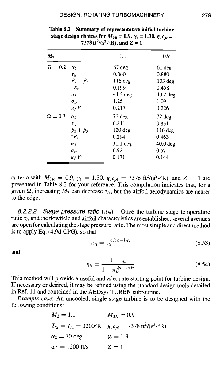
Table 8.2 Summary of representative initial turbine
stage design choices for
M3R =
0.9, % = 1.30,
gccm =
7378 ft2/(sZ-°R), and Z = 1
M2 1.1 0.9
S2 = 0.2 13l 2 67 deg 61 deg
rts 0.860 0.880
f12 "~ f13
116 deg 103 deg
°Rt
0.199 0.458
0~3 41.2 deg 40.2 deg
ffxr
1.25 1.09
U~ V'
0.217 0.226
g2 = 0.3 or2 72 deg 72 deg
rts
0.811 0.831
f12 + f13 120 deg 116 deg
°Rt 0.294 0.463
a'3 31.1 deg 40.0 deg
crxr 0.92 0.67
u/V'
0.171 0.144
criteria with
M3R
= 0.9, Ft = 1.30,
gcCpt =
7378 ft2/(s2-°R), and Z = 1 are
presented in Table 8.2 for your reference. This compilation indicates that, for a
given f2, increasing M2 can decrease rt~, but the airfoil aerodynamics are nearer
to the edge.
8.2.2.2 Stage pressure ratio
(:rrts).
Once the turbine stage temperature
ratio
rts
and the flowfield and airfoil characteristics are established, several avenues
are open for calculating the stage pressure ratio. The most simple and direct method
is to apply Eq. (4.9d-CPG), so that
~rts = rt~ '/(y'-l)e"
(8.53)
and
1-- Vts
--
.(×,-1)/×, (8.54)
Ors 1 - nts
This method will provide a useful and adequate starting point for turbine design.
If necessary or desired, it may be refined using the standard design tools detailed
in Ref. 11 and contained in the AEDsys TURBN subroutine.
Example case:
An uncooled, single-stage turbine is to be designed with the
following conditions:
M: = 1.1 M3R = 0.9
Tt2 = Ttl
= 3200°R
gcCpt
= 7378 ft2/(s2-°R)
ot2 = 70 deg Yt = 1.3
mr
= 1200 ft/s Z = 1
280
Then
AIRCRAFT ENGINE DESIGN
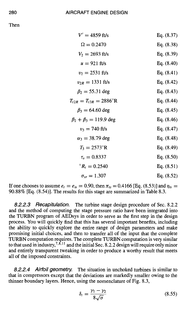
V' = 4859 ft/s Eq. (8.37)
f2 = 0.2470 Eq. (8.38)
V2 = 2693 ft/s Eq. (8.39)
u = 921 ft/s Eq. (8.40)
v2 = 2531 ft/s Eq. (8.41)
v2n = 1331 ft/s Eq. (8.42)
f12 = 55.31 deg Eq. (8.43)
Tt2R = Tt3R =
2886°R Eq. (8.44)
/33 = 64.60 deg Eq. (8.45)
/32 + f13 = 119.9 deg Eq. (8.46)
v3 = 740 ft/s Eq. (8.47)
~3 = 38.79 deg Eq. (8.48)
T3 = 2573°R Eq. (8.49)
rs = 0.8337 Eq. (8.50)
°Rt = 0.2540 Eq. (8.51)
tTxr
~---
1.307 Eq. (8.52)
If one chooses to assume
et
---- ets = 0.90, then zrts = 0.4166 [Eq. (8.53)] and r/ts =
90.88% [Eq. (8.54)]. The results for this stage are summarized in Table 8.3.
8.2.2.3 Recapitulation.
The turbine stage design procedure of Sec. 8.2.2
and the method of computing the stage pressure ratio have been integrated into
the TURBN program of AEDsys in order to serve as the first step in the design
process. You will quickly find that this has several important benefits, including
the ability to quickly explore the entire range of design parameters and make
promising initial choices, and then to transfer all of the input that the complete
TURBN computation requires. The complete TURBN computation is very similar
to that used in industry, 7,8,11 and the initial Sec. 8.2.2 design will require only minor
and entirely transparent tweaking in order to produce a worthy result that meets
all of the imposed constraints.
8.2.2.4 Airfoil geometry.
The situation in unchoked turbines is similar to
that in compressors except that the deviations are markedly smaller owing to the
thinner boundary layers. Hence, using the nomenclature of Fig. 8.3,
Yl -- Y2
~t - (8.55)
DESIGN: ROTATING TURBOMACHINERY
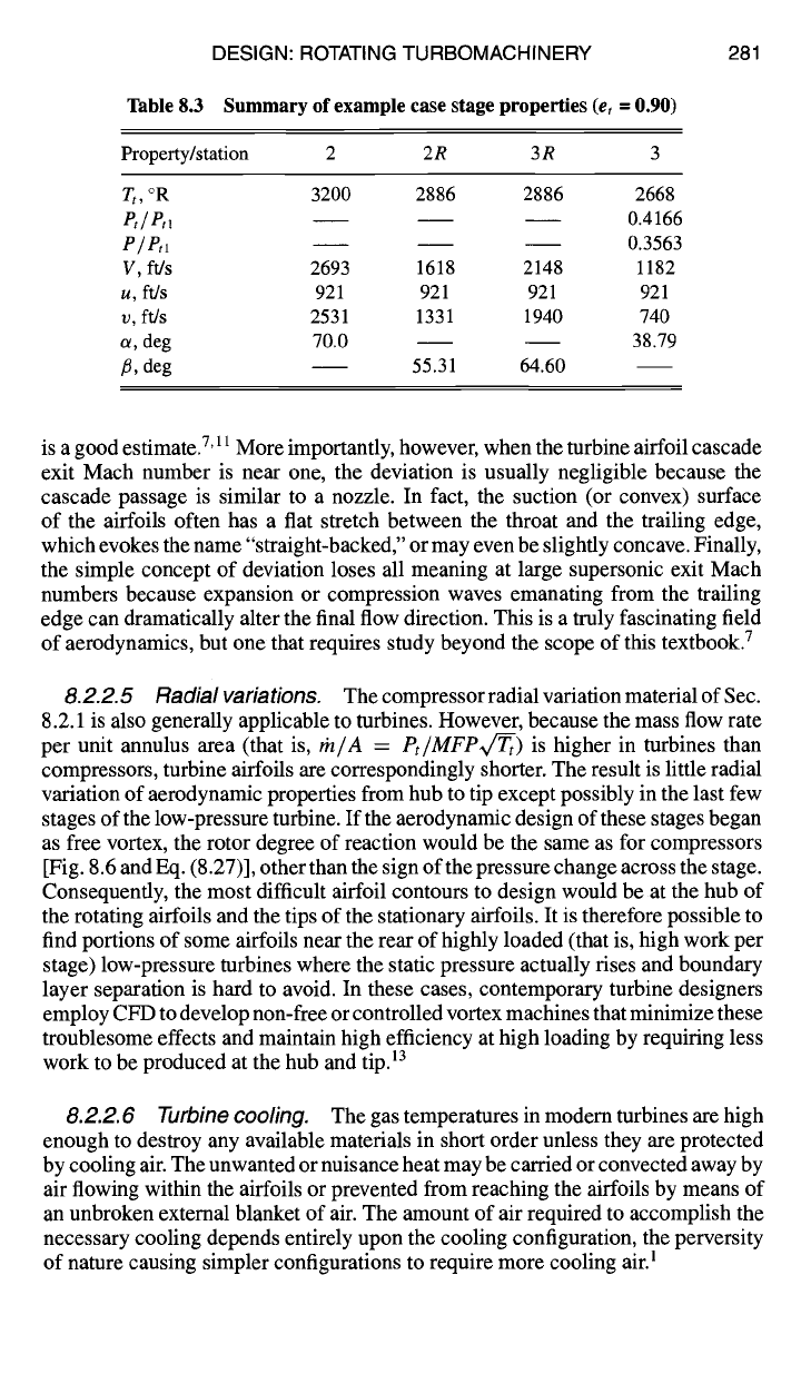
Table 8.3 Summary of example case stage properties
(et
= 0.90)
281
Property/station 2 2R 3R 3
Tt, °R 3200 2886 2886 2668
Pt/Pt~ 0.4166
e/erl 0.3563
V, ft/s 2693 1618 2148 1182
u, ft/s 921 921 921 921
v, ft/s 2531 1331 1940 740
c¢, deg 70.0 38.79
/~, deg 55.31 64.60
is a good estimate.7'
11
More importantly, however, when the turbine airfoil cascade
exit Mach number is near one, the deviation is usually negligible because the
cascade passage is similar to a nozzle. In fact, the suction (or convex) surface
of the airfoils often has a flat stretch between the throat and the trailing edge,
which evokes the name "straight-backed," or may even be slightly concave. Finally,
the simple concept of deviation loses all meaning at large supersonic exit Mach
numbers because expansion or compression waves emanating from the trailing
edge can dramatically alter the final flow direction. This is a truly fascinating field
of aerodynamics, but one that requires study beyond the scope of this textbook. 7
8.2.2.5 Radial variations. The compressor radial variation material of Sec.
8.2.1 is also generally applicable to turbines. However, because the mass flow rate
per unit annulus area (that is, rh/A = Pt/MFP~c~t) is higher in turbines than
compressors, turbine airfoils are correspondingly shorter. The result is little radial
variation of aerodynamic properties from hub to tip except possibly in the last few
stages of the low-pressure turbine. If the aerodynamic design of these stages began
as free vortex, the rotor degree of reaction would be the same as for compressors
[Fig. 8.6 and Eq. (8.27)], other than the sign of the pressure change across the stage.
Consequently, the most difficult airfoil contours to design would be at the hub of
the rotating airfoils and the tips of the stationary airfoils. It is therefore possible to
find portions of some airfoils near the rear of highly loaded (that is, high work per
stage) low-pressure turbines where the static pressure actually rises and boundary
layer separation is hard to avoid. In these cases, contemporary turbine designers
employ CFD to develop non-free or controlled vortex machines that minimize these
troublesome effects and maintain high efficiency at high loading by requiring less
work to be produced at the hub and
tip. 13
8.2.2. 6 Turbine cooling.
The gas temperatures in modem turbines are high
enough to destroy any available materials in short order unless they are protected
by cooling air. The unwanted or nuisance heat may be carded or convected away by
air flowing within the airfoils or prevented from reaching the airfoils by means of
an unbroken extemal blanket of air. The amount of air required to accomplish the
necessary cooling depends entirely upon the cooling configuration, the perversity
of nature causing simpler configurations to require more cooling air. 1
282 AIRCRAFT ENGINE DESIGN
0.6
0.5-
0.4-
0.3-
0.2
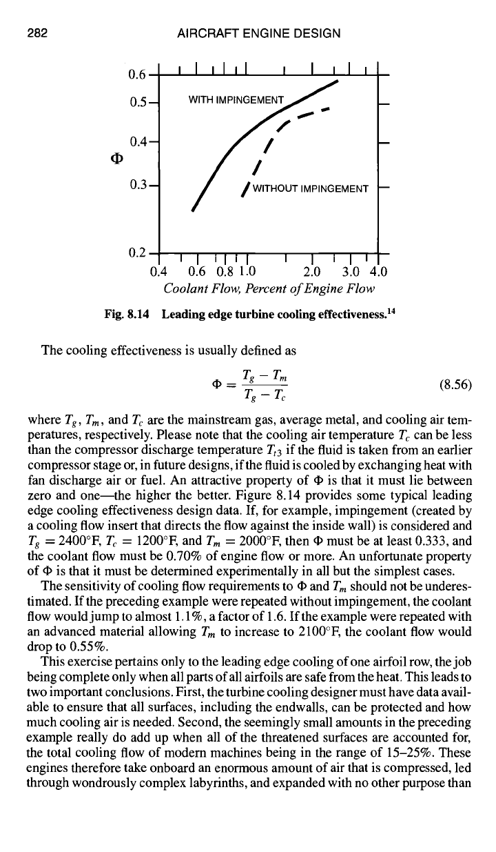
Fig. 8.14
IIlil I I ill
WITH IMPINGEMENT/
/ WITHOUT IMPINGEMENT
I I till t I I I ~
0.4 0.6 0.8 1.0 2.0 3.0 4.0
Coolant Flow, Percent of Engine Flow
Leading edge turbine cooling effectiveness. ~4
The cooling effectiveness is usually defined as
do _ Tg - Tm
(8.56)
7~- Tc
where
Tg, Tm, and Tc are
the mainstream gas, average metal, and cooling air tem-
peratures, respectively. Please note that the cooling air temperature Tc can be less
than the compressor discharge temperature Tt3 if the fluid is taken from an earlier
compressor stage or, in future designs, if the fluid is cooled by exchanging heat with
fan discharge air or fuel. An attractive property of do is that it must lie between
zero and one--the higher the better. Figure 8.14 provides some typical leading
edge cooling effectiveness design data. If, for example, impingement (created by
a cooling flow insert that directs the flow against the inside wall) is considered and
Tg = 2400°F, Tc = 1200°F, and
T m =
2000°F, then do must be at least 0.333, and
the coolant flow must be 0.70% of engine flow or more. An unfortunate property
of do is that it must be determined experimentally in all but the simplest cases.
The sensitivity of cooling flow requirements to do and
Tm
should not be underes-
timated. If the preceding example were repeated without impingement, the coolant
flow would jump to almost 1.1%, a factor of 1.6. If the example were repeated with
an advanced material allowing
Tm
to increase to 2100°F, the coolant flow would
drop to 0.55%.
This exercise pertains only to the leading edge cooling of one airfoil row, the job
being complete only when all parts of all airfoils are safe from the heat. This leads to
two important conclusions. First, the turbine cooling designer must have data avail-
able to ensure that all surfaces, including the endwalls, can be protected and how
much cooling air is needed. Second, the seemingly small amounts in the preceding
example really do add up when all of the threatened surfaces are accounted for,
the total cooling flow of modem machines being in the range of 15-25%. These
engines therefore take onboard an enormous amount of air that is compressed, led
through wondrously complex labyrinths, and expanded with no other purpose than
DESIGN: ROTATING TURBOMACHINERY 283
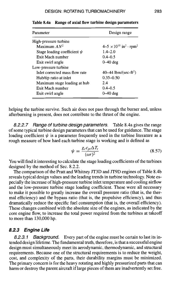
Table 8.4a Range of axial flow turbine design parameters
Parameter Design range
High-pressure turbine
Maximum
AN 2
Stage loading coefficient 7t
Exit Mach number
Exit swirl angle
Low-pressure turbine
Inlet corrected mass flow rate
Hub/tip ratio at inlet
Maximum stage loading at hub
Exit Mach number
Exit swirl angle
4-5 x 101° in 2. rpm 2
1.4-2.0
0.4-0.5
040 deg
40-44 lbrrd(sec-ft 2)
0.35-0.50
2.4
0.4-0.5
04-40 deg
helping the turbine survive. Such air does not pass through the burner and, unless
afterburning is present, does not contribute to the thrust of the engine.
8.2.2. 7 Range of turbine design parameters.
Table 8.4a gives the range
of some typical turbine design parameters that can be used for guidance. The stage
loading coefficient ~p is a parameter frequently used in the turbine literature as a
rough measure of how hard each turbine stage is working and is defined as
-- gccptA Tt
(8.57)
(wr) 2
You will find it interesting to calculate the stage loading coefficients of the turbines
designed by the method of Sec. 8.2.2.
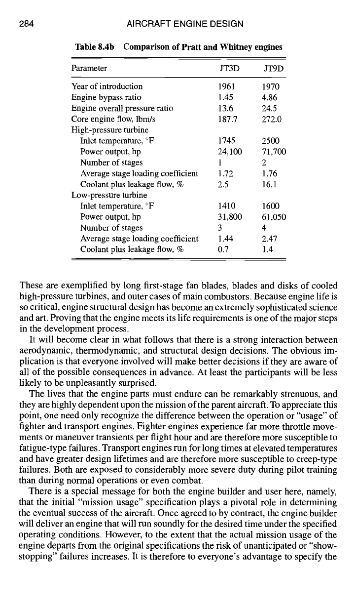
The comparison of the Pratt and Whitney JT3D and JT9D engines of Table 8.4b
reveals typical design values and the leading trends in turbine technology. Note es-
pecially the increase of high-pressure turbine inlet temperature and cooling airflow
and the low-pressure turbine stage loading coefficient. These were all necessary
to make it possible to greatly increase the overall pressure ratio (that is, the ther-
mal efficiency) and the bypass ratio (that is, the propulsive efficiency), and thus
dramatically reduce the specific fuel consumption (that is, the overall efficiency).
These changes combined with the absolute size of the engines, as indicated by the
core engine flow, to increase the total power required from the turbines at takeoff
to more than 130,000 hp.
8.2.3 Engine Life
8.2.3.1 Background.
Every part of the engine must be certain to last its in-
tended design lifetime. The fundamental truth, therefore, is that a successful engine
design must simultaneously meet its aerodynamic, thermodynamic, and structural
requirements. Because one of the structural requirements is to reduce the weight,
cost, and complexity of the parts, their durability margins must be minimized.
The primary concern is for the heavy rotating and highly pressurized parts that can
harm or destroy the parent aircraft if large pieces of them are inadvertently set free.
284 AIRCRAFT ENGINE DESIGN
Table 8.4b Comparison of Pratt and Whitney engines
Parameter JT3D JT9D
Year of introduction 1961 1970
Engine bypass ratio 1.45 4.86
Engine overall pressure ratio 13.6 24.5
Core engine flow, lbm/s 187.7 272.0
High-pressure turbine
Inlet temperature, ° F 1745 2500
Power output, hp 24,100 71,700
Number of stages 1 2
Average stage loading coefficient 1.72 1.76
Coolant plus leakage flow, % 2.5 16.1
Low-pressure turbine
Inlet temperature, ° F 1410 1600
Power output, hp 31,800 61,050
Number of stages 3 4
Average stage loading coefficient 1.44 2.47
Coolant plus leakage flow, % 0.7 1.4
These are exemplified by long first-stage fan blades, blades and disks of cooled
high-pressure turbines, and outer cases of main combustors. Because engine life is
so critical, engine structural design has become an extremely sophisticated science
and art. Proving that the engine meets its life requirements is one of the major steps
in the development process.
It will become clear in what follows that there is a strong interaction between
aerodynamic, thermodynamic, and structural design decisions. The obvious im-
plication is that everyone involved will make better decisions if they are aware of
all of the possible consequences in advance. At least the participants will be less
likely to be unpleasantly surprised.
The lives that the engine parts must endure can be remarkably strenuous, and
they are highly dependent upon the mission of the parent aircraft. To appreciate this
point, one need only recognize the difference between the operation or "usage" of
fighter and transport engines. Fighter engines experience far more throttle move-
ments or maneuver transients per flight hour and are therefore more susceptible to
fatigue-type failures. Transport engines run for long times at elevated temperatures
and have greater design lifetimes and are therefore more susceptible to creep-type
failures. Both are exposed to considerably more severe duty during pilot training
than during normal operations or even combat.
There is a special message for both the engine builder and user here, namely,
that the initial "mission usage" specification plays a pivotal role in determining
the eventual success of the aircraft. Once agreed to by contract, the engine builder
will deliver an engine that will run soundly for the desired time under the specified
operating conditions. However, to the extent that the actual mission usage of the
engine departs from the original specifications the risk of unanticipated or "show-
stopping" failures increases. It is therefore to everyone's advantage to specify the
DESIGN: ROTATING TURBOMACHINERY 285
mission usage correctly at the outset. Furthermore, it is essential that the parts be
realistically exposed to the life-consuming portions of the engine usage spectrum
early and repeatedly in the development process. This is done best with the safety
and control made possible by simulated altitude testing in ground test facilities
and must be continued until the required engine durability has been confidently
demonstrated.
This foreword is meant to underscore the overwhelming importance of structural
design for modern aircraft engines. What follows next is an abbreviated, qualitative
introduction to the design process. The reader should be aware that much has been
written on this subject, and that adequate reference material exists to satisfy almost
any curiosity. We are indeed fortunate to be able to include an excellent review of
Turbine Engine Life Management, authored by Dr. William Cowie, a pioneer and
foremost expert in the field, as Appendix N. You will find this to supply a unique
and invaluable background for the engine design process.
The first step in the iterative structural design process is to estimate the stresses
that will be experienced by each part. The stresses stem from the environment to
which the parts are exposed and can, in turn, be regarded as the forcing functions
that consume available life. The second step is to evaluate the response of the parts
in terms of their life expectancy. Both steps require intimate knowledge of many
properties of the materials involved. If the life of any given part is inadequate (or
excessive), its design is changed, and the process is repeated until a satisfactory
solution is found.
We are about to embark on the development of several structural design tools
consistent with the philosophy of this textbook. Their focus will be on the main
source of stresses in rotating parts--the centrifugal force. For the sake of perspec-
tive, it is well to bear in mind the fact that the centrifugal force experienced by
an element of material rotating at 10,000 rpm and a radius of 1 ft is equivalent to
34,000 g!
Nevertheless, there are many other forces at work that can consume the life (or
destroy) stationary or rotating parts, all of which must eventually be accounted
for in the design and test process. Some of the most important, not necessarily in
order of importance, include the following:
1) Airfoil bending moments are caused by the pressure differences across the sta-
tionary and rotating airfoils (or their lift) and are greatest where they are fastened.
The centrifugal force can also cause airfoils with complex three-dimensional
shapes to twist and bend.
2) Flutter (self-induced vibration) is an unsteady aerodynamic phenomenon
that airfoils and/or disks can spontaneously experience, in which they vibrate at a
system natural frequency and for which the driving energy is extracted from the
flowing gas. This is most commonly found in fan and compressor airfoil rows and
comes in many varieties (for example, supersonic flutter, stall flutter, and choke
flutter). Once flutter begins, the life of the parts is measured in minutes because
of the large stresses and high frequency vibrations (> 1000 Hz) that result. Flutter
must be avoided at any cost, but the analysis tools are beyond the scope of this
textbook.
3) Airfoils, disks, and other flowpath parts are exposed to unsteady aerodynamic
forces, such as buffeting (forced vibration) and high cycle fatigue (HCF) that result
from temporally and/or spatially nonuniform flows. Care must be taken to avoid