Mattingly J.D., Heiser W.H., Pratt D.T. Aircraft Engine Design
Подождите немного. Документ загружается.

356 AIRCRAFT ENGINE DESIGN
and mass (molecules) may be transported laterally as well. If the two streams have
different molecular identities, the shear layer is also a mixing layer. By analogy
with the definition of boundary layer thickness, the mixing layer thickness
~m
is
defined as the region within which the mole fractions of mixant gases differ by 1%
or more from their respective values in the unmixed streams.
The velocity ratio r =
U2/U1
and the velocity difference AU = U1 - U2 are
related to the mean convective velocity U¢ = ( U1 -+- U2)/2 by
1-r
For very small A U the shear layer may be laminar and time steady. As the
velocity difference A U between the two streams is increased, the laminar shear
layer becomes unstable, and large vortices are periodically formed between the
two streams, just as in the case for round jets, as shown schematically in Fig. 9.18.
The cross-hatched area shown in the third vortex structure in Fig. 9.18 represents
the fully micromixed region. Of course, molecular diffusion occurs continuously at
the fuel-air interface immediately after the splitter plate, and the fully micromixed
end state is simply the cumulative result of interfacial diffusion.
The time-mean growth rate of a turbulent shear layer is given approximately
by 19
~ 3B 2 1 - r (9.53)
---
X
where ~ is the local shear layer width at a distance x downstream of the splitter
plate, and where B is the ratio of the Prandtl mixing length ~m to the shear layer
width, B =
f.m/&
The ratio B is an empirical constant and can only be determined
from experimental data. 19 A time-averaged picture of the growth of the shear layer
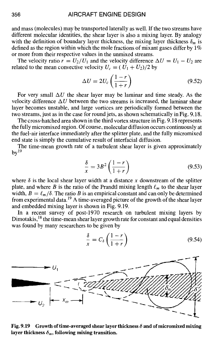
and embedded mixing layer is shown in Fig. 9.19.
In a recent survey of post-1970 research on turbulent mixing layers by
Dimotakis, 18 the time-mean shear layer growth rate for constant and equal densities
was found by many researchers to be given by
1-r
X
/
"3
/
Fig. 9.19 Growth of time-averaged shear layer thickness 6 and ofmicromixed mixing
layer thickness
6m,
following mixing transition.
DESIGN: COMBUSTION SYSTEMS 357
where C~ was reported as varying from 0.25 to 0.45. Note that Eqs. (9.54) and (9.53)
are of the same form and differ only in the representation of the proportionality
constant.
When the mass densities in the two streams are different, the convective velocity
Uc
is given by 18
U 1 -~- Sl/2U2
Uc -- 1 + s72
(9.55)
where s =
P2/Pl.
The corresponding growth rate of the shear layer is also consid-
erably more complex than Eq. (9.54):
C,s( 1-r ) (~) { (1--s1/2)/(l+slh) }
x = 1 + s'/2r
1 - 1 + 1.29(1 +
r)/(1 - r)
(9.56)
Note that Eq. (9.56) reduces to Eq. (9.54) when s = 1.
By inspection of Fig. 9.18, it is apparent that, at any axial station, micromixing
(indicated by dashed lines) is not complete throughout the shear layer. In fact,
for the first one or two vortices sketched in Fig. 9.18, it may be seen that com-
paratively little micromixing has yet occurred. The distance downstream of the
splitter plate at which significant amount of mixed fluid is first present is called the
mixing transition point. The mixing transition occurs approximately at the point
where
(UI -- U2)~ ~
10 (9.57)
P
where v is a representative average value of the molecular kinematic viscosity
within the shear layer. Following the mixing transition, the time-averaged mi-
cromixing layer is observed to grow approximately as a constant fraction of the
shear layer,
~m
--
~ 0.49 (9.58)
as illustrated in Fig. 9.19.
The composition of the gases within the mixing layer is characterized by the
volumetric entrainment ratio Ev, defined as the volume ratio of high-speed fluid
to low-speed fluid entrained within each vortex structure, that is, "wrapped up"
into each vortex or "jelly-roll" structure as shown in Fig. 9.18. The volumetric
entrainment ratio is observed to depend on both the density ratio and velocity
ratio ~s as
1-r
The corresponding mass-basis and mole-basis entrainment ratios
Em and En are
given by
Em=--Ev
and E.=
M2Em
(9.60)
s M~
358 AIRCRAFT ENGINE DESIGN
where M1 and M2 are the mean or apparent molecular weights of the gases in
streams 1 and 2, respectively.
TM
9.1.5 Total Pressure Loss
The main burner or combustor is the engine component immediately down-
stream of the high-pressure compressor. For reasons to be shown presently, the
main burner requires an inlet velocity which is much lower than that leaving
the high-pressure compressor, so that the flow velocity must be greatly reduced
between these two components. As the required flow diffuser inserted into the
flowpath is a passive device, adding neither mechanical nor thermal energy to the
flow, it is not clear from a strictly logical point of view where design responsibility
for this component should lie. Historically, it has been regarded as a part of the
main burner, and so it is included here.
In this section it will first be shown how to estimate the main burner diffuser total
pressure loss. Next, the principal source of total pressure loss in the main burner
liner (see Fig. 9.1) namely, stirring and mixing with jets, will be considered. Finally,
the total pressure loss in the afterburner (see Fig. 9.2) will be analyzed.
A number of assumptions will be made in common for all of the derivations
to follow. They are as follows: 1) flow is quasi-one dimensional, 2) mass density
varies with temperature, but not with pressure, n 3) combustion in the main burner
is at constant pressure, and 4) the mass flow rate of fuel is neglected compared to
that of air.
9. 1.5.1 Flat-wall diffuser.
Although the purpose of a flow diffuser is to
reduce axial velocity in order to gain static pressure, this must be accomplished
in a very short axial distance and with a minimal loss of total pressure. As with
the diffusing flow in compressor blade passages, this is not easily accomplished
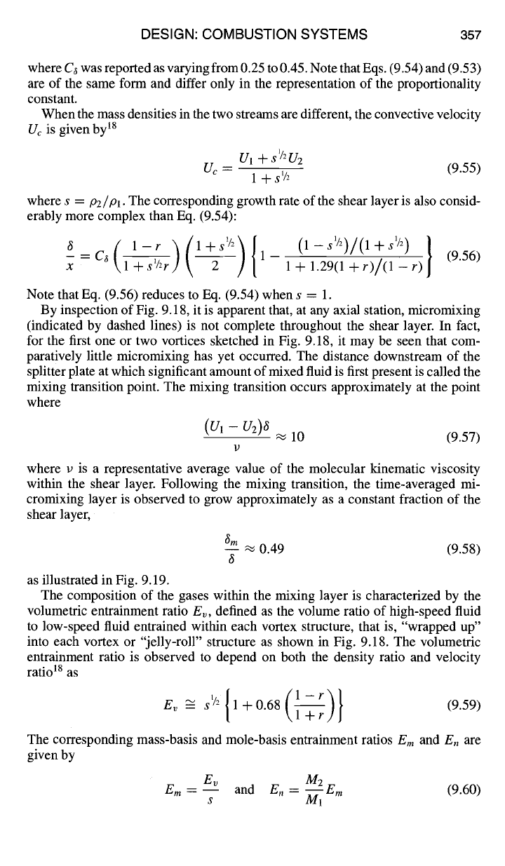
without flow separation. The geometry and nomenclature of a generic fiat wall
diffuser with flow-straightening section are shown in Fig. 9.20. The entry and exit
stations of Fig. 9.20 correspond to compressor outlet, station 3.1, and burner inlet,
station 3.2, respectively, in Fig. 9.1. Typically, an area ratio
AR = A2/A1
of 3 to 5
is required to diffuse the flow, although an area ratio as great as 10 or even 20 may
be required for some engine designs. A "tailpipe" of length
La
can be added for
improved performance.
\
L tan8
+ 2/_/--~
H 2
Fig. 9.20 Geometry of a flat-wall diffuser with tailpipe. 2°m
DESIGN: COMBUSTION SYSTEMS 359
Strictly speaking, both the main burner and afterbumer diffusers are annular
diffusers, rather than the planar diffuser pictured in Fig. 9.20. Because an annular
flow passage has inner and outer radii
ri and ro,
respectively, the geometrical
variables that define the shape of an annular (quasi-flat-wall) diffuser are given by
AR -- A2 -- H2rm2 -- 1 + 2rmz L tanO
A1 H1 rml rml HI
or
L t/rml"~ (AR-
1)
H-~ =
I Ikrm21
2tanO
(9.61)
where H is the radial height H =
(ro - ri) and rm
is the mean radius, r,, --
(ro +ri)/2.
Note that when the inlet and exit mean radii are equal Eq. (9.61) reduces to the
geometrical relationship for a planar flat-wall diffuser given on Fig. 9.20.
There are a number of measures used to characterize the performance of a
diffuser. The pressure recovery coefficient Ce is defined by 2°'21
P2 - P1
C p _4_
(9.62)
ql
In the case of isentropic flow, that is, flow with neither wall friction nor flow
separation, and with the assumptions listed at the beginning of this section, con-
servation of mass leads immediately to the ideal pressure recovery coefficient
Cpid:
(/°2 --
el)ise n ql - qZisen 1
Cpi d
----" --
-- 1 - -- (9.63)
ql ql AR 2
The ratio of actual-to-ideal pressure recovery is a logical measure of diffuser
performance and is called the diffuser effectiveness or diffusion efficiency r/D,
Ce
OD -- (9.64)
Cpid
It is interesting to note that ~/D defined by Eq. (9.64) is identical to the isentropic
diffuser efficiency 0D defined by the ratio of ideal-to-actual enthalpy change, 22
h2s - hi
OD ---- (9.65)
h2 - hi
The total pressure loss coefficient is defined by
( ~ ( 1 )
APt _ Ptl-Pt2 =Cmd-Cp
= 1-~-~ (1--~n) (9.66)
\ ql ID ql
and the related total pressure ratio ~o is
t)t2 (APt/ql)D
(1 -
1/AR2)(1 - riD )
7"/" 0 ~" --
1 -- 1 - (9.67)
Ptl 1 + 2/vM 2 1 + 2/vM21
All of the preceding figures of merit are useful, depending on the perspective
or interest of the designer. If the primary design goal of the diffuser is maximum
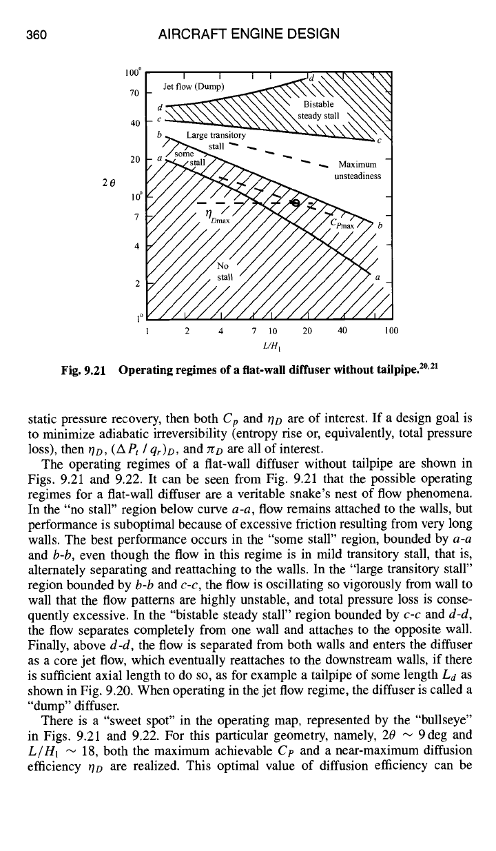
360 AIRCRAFT ENGINE DESIGN
20
Fig. 9.21
100 °
, ,
,,
Jet flow (Dump)
7o
d ~.~_~~~ steady~~stall \~
40
/~tall "" -,...
20 ~1~ -- "" -- Maximum
10 °
7
4
2
,o
2 4 7 10 20 40 100
L/H I
Operating regimes
of a flat-wall diffuser without tailpipe. 2°'21
static pressure recovery, then both
Cp
and OD are of interest. If a design goal is
to minimize adiabatic irreversibility (entropy rise or, equivalently, total pressure
loss), then
rlD, (APt /
qr)D,
and
no are
all of interest.
The operating regimes of a flat-wall diffuser without tailpipe are shown in
Figs. 9.21 and 9.22. It can be seen from Fig. 9.21 that the possible operating
regimes for a flat-wall diffuser are a veritable snake's nest of flow phenomena.
In the "no stall" region below curve
a-a,
flow remains attached to the walls, but
performance is suboptimal because of excessive friction resulting from very long
walls. The best performance occurs in the "some stall" region, bounded by
a-a
and
b-b,
even though the flow in this regime is in mild transitory stall, that is,
alternately separating and reattaching to the walls. In the "large transitory stall"
region bounded by
b-b
and
c-c,
the flow is oscillating so vigorously from wall to
wall that the flow patterns are highly unstable, and total pressure loss is conse-
quently excessive. In the "bistable steady stall" region bounded by
c-c
and
d-d,
the flow separates completely from one wall and attaches to the opposite wall.
Finally, above
d-d,
the flow is separated from both walls and enters the diffuser
as a core jet flow, which eventually reattaches to the downstream walls, if there
is sufficient axial length to do so, as for example a tailpipe of some length
Ld
as
shown in Fig. 9.20. When operating in the jet flow regime, the diffuser is called a
"dump" diffuser.
There is a "sweet spot" in the operating map, represented by the "bullseye"
in Figs. 9.21 and 9.22. For this particular geometry, namely, 20 --~ 9deg and
L/H1 "~
18, both the maximum achievable
Cp
and a near-maximum diffusion
efficiency r/D are realized. This optimal value of diffusion efficiency can be
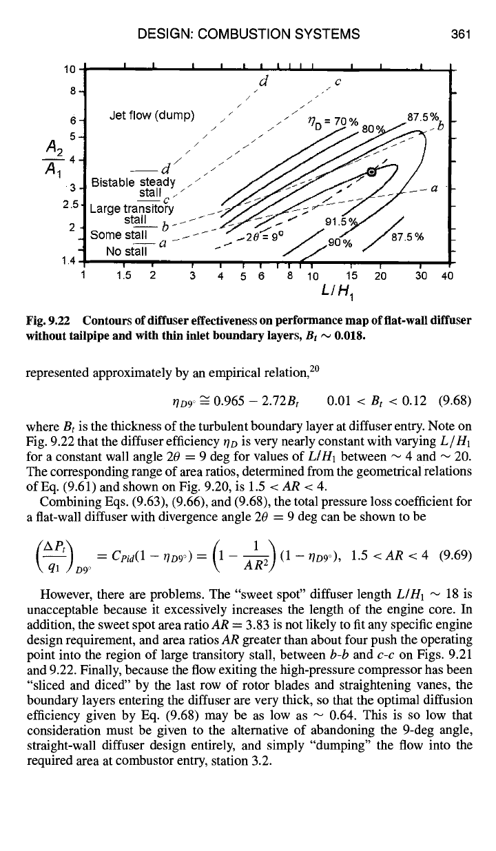
DESIGN: COMBUSTION SYSTEMS 361
10
8-
6-
A2
5-
4-
A1
"3=
2.5,
2-
1.4
I I I I I I I I I I I I i ,I ,
d c
/
J
// I /
Jet flow (dump) ~" i r]
-
70% 875% b
Bistable steady . z" /~ f .~Z-.Y" ...--~ / / /
Large ~rans~ory .~'/-j" _..~-'-~;, ~ /- /"
Some stall ~ ~ ~ ~ " ~20"= 9~ //87.5°/°
.o sty".
....
% /
.....
I i [ I [ | [I I I I I 1 I i |
1.5 2 3 4 5 6 8 10 15 20 30 40
L/H 1
Fig. 9.22 Contours of diffuser effectiveness on performance map of flat-wall diffuser
without tailpipe and with thin inlet boundary layers,
Bt ~
0.018.
represented approximately by an empirical relation, 2°
/7D9 ~ 0.965 -- 2.72Bt 0.01
<
B t
< 0.12 (9.68)
where Bt is the thickness of the turbulent boundary layer at diffuser entry. Note on
Fig. 9.22 that the diffuser efficiency ~o is very nearly constant with varying
L/H1
for a constant wall angle 20 = 9 deg for values of
L/H1
between "-- 4 and --- 20.
The corresponding range of area ratios, determined from the geometrical relations
of Eq. (9.61) and shown on Fig. 9.20, is 1.5 <
AR < 4.
Combining Eqs. (9.63), (9.66), and (9.68), the total pressure loss coefficient for
a fiat-wall diffuser with divergence angle 20 = 9 deg can be shown to be
= Cpid(l --
/'/D9 o) = --
(1
-- 0D9O), 1.5 <
AR
< 4
(9.69)
\ ql /D9 o
However, there are problems. The "sweet spot" diffuser length
L/H1
~ 18 is
unacceptable because it excessively increases the length of the engine core. In
addition, the sweet spot area ratio
AR
= 3.83 is not likely to fit any specific engine
design requirement, and area ratios AR greater than about four push the operating
point into the region of large transitory stall, between
b-b
and
c-c
on Figs. 9.21
and 9.22. Finally, because the flow exiting the high-pressure compressor has been
"sliced and diced" by the last row of rotor blades and straightening vanes, the
boundary layers entering the diffuser are very thick, so that the optimal diffusion
efficiency given by Eq. (9.68) may be as low as --~ 0.64. This is so low that
consideration must be given to the alternative of abandoning the 9-deg angle,
straight-wall diffuser design entirely, and simply "dumping" the flow into the
required area at combustor entry, station 3.2.
362 AIRCRAFT ENGINE DESIGN
9.1.5.2 Dump diffuser. At first glance, it may seem that the dump diffuser,
operating in the "jet flow" region above line d-d in Figs. 9.21 and 9.22, is the
worst possible case for flow diffusion, but, in fact, the bistable stall and large
transitory stall regions bounded by b-b and d-d in Figs. 9.21 and 9.22 are much
worse. 2°,21 Worst of all, in the large transitory stall region the flow separates and
then momentarily reattaches to only one of the downstream walls. This in turn
causes another, subsequent sudden expansion as the bifurcated flow tries to reattach
and fill the duct. The separated flow acts as a bistable oscillator, jumping from
wall to wall in a periodic Coanda effect, presenting randomly varying, nonuniform
velocity profiles to downstream components and causing an excessive loss of total
pressure, which can be 10-40% greater than a dump diffuser! Thus, a dump diffuser
is the "best worst" case for a flat-wall diffuser.
Consider the classic case of head loss or total pressure loss caused by a sudden
expansion in a duct. 21 Figure 9.20, with 20 = 180 deg and La ~ H2, is the control
volume for this analysis. (The tailpipe length La has to be sufficiently long for
the jet core flow at entry to reattach to both walls.) By applying the equations
of conservation of mass and linear momentum to this control volume, together
with the assumptions listed in the introduction to this section, the reader may (and
should) verify that the pressure recovery coefficient, total pressure loss coefficient,
and diffuser efficiency for the dump diffuser are given by
(AR-I
F ]
(1),
_-,-
ana
[CP]d,mp = 2 I~ AR 2 ]' k ql Jd,mp ~ '
2
[qD]dump =
1 + AR (9.70)
For the "sweet spot" diffuser area ratio AR = 3.83, Eq. (9.70c) predicts a dump
diffuser efficiency of only 0.414, which is considerably less than the absolutely
best value of qD = 0.91 obtainable by a thin-boundary layer, 2 0 = 9 deg flat-wall
diffuser of area ratio AR = 3.83 and length-to-entry height ratio L/H1 = 18. Ways
to overcome this perplexing problem will be presented in Sec. 9.2.3.
9.1.5.3 Main burner. In the early day of turbojet engine development, the
total pressure loss of the combustor was regarded as just another parasitic loss, in
addition to those of the diffuser, compressor and turbine, all of which reduced the
marginal engine performance achievable at the time. Consequently, main burner
designers were under great pressure to minimize total pressure loss, or at least
to justify the excessive amounts they claimed were necessary to achieve ade-
quate combustion stability and efficiency. As engine designs evolved, increasing
compression ratios and turbine inlet temperatures created a demand for increased
compressor bleed airflow for turbine blade cooling. Moreover, because the bleed
air itself was becoming increasingly hot, even greater flow rates were needed
to adequately protect the turbine blades. Consequently, the main burner is today
viewed not only as the source of thermal energy required by the propulsion cycle,
but also as a necessary flow constriction or circuit resistance, which must provide
adequate flow area blockage to maintain the required static pressure drop between
compressor bleed outlet and turbine inlet. This is especially critical if the turbine
first stage stator vanes depend on film cooling to protect their leading edges. If
~>~
~.=~
~ga
~'~ ~
~ .
~N
i
~
I. ~.
I
II
N
I I
b~
I
I t°l
".-.1
0
o'0
t~
~>
II
+
I
+
II
I
~.~X.~.~=~ ~.~ ~. ~ --~ ~ ~ o~ = =~ = ~q ~. ~ = ~ .~.~
o-o=~ ~
•
~.~o~=~.~ ...~
o~ ~- ~-~~ ~ ~: ~ .~ ..... o~
ii~ ~ ~ "'~ ~
o ~ ~'=.n'= ~ -~
- ~ ~,,..=o~ ~ ~ =,, ~ o ~
0 ~'0 0" ~'0
~" ~] ~
~. ~ ~ ~" ~ C~ ~ . ~ ~ "" 0 ~ 0 ~'"
~I ~ ~ 0 ~. ~ ' ~
"
' 0
~o" I ~1 ~
~-~ ~0 ~ i::r0~ In ~ ¢~ ~ 0 ~'
~ .~ ~" - ~
.
"0 0 ~ ~ ~ I~
o
ITI
¢aO
0
z
0
0
DD
C
O0
0
Z
O0
-<
O0
--I
m
oo
¢...0
O)
¢aO
364 AIRCRAFT ENGINE DESIGN
cross-sectional area AL, Eq. (9.71) becomes
qr ]MB \
lhr / \AL/ L\'-~j] -- rpz
(9.72)
Typical values for the primary zone of a 1950s turbojet engine are fez ~ 4,
Aj/AL
= 0.12,
AL/Ar
= 0.65, and
rhpz/rhr
= 0.3 (Ref. 10), for which
Eq. (9.72) gives a total pressure loss coefficient of about 14.
All of the terms in Eq. (9.72) are fixed by various engine design criteria that will
be presented in Sec. 9.2, except for (Ar/Aj), the ratio of liner cross-sectional area
to swifter jet (vena contracta) area. It is this parameter that determines the amount
of constriction or blockage required to obtain any given level of primary zone inlet
swirler jet velocity. Therefore, the next task is to determine how great this swirler
jet velocity has to be to achieve the degree of micromixing required for effective
flameholding in the primary zone.
To do this, it is necessary to first estimate the time required for micromixing to
occur, then ensure that the residence time or "stay time" in the primary zone is
equal to or greater than the micromixing time.
The micromixing time
tm
is estimated by assuming that the characteristic time
for decay of a turbulent eddy is approximately the same as that required for reduc-
tion of a temperature or concentration fluctuation, 23
2 !
tm ~
(9.73)
where H is a characteristic linear dimension of the primary zone, which we take to
be the liner height or "dome height" Hc and er is the rate of dissipation of
turbulence kinetic energy, which is equal to the mixing power of the stirring jets
per unit mass in the primary zone,
pjAjVj(V2/2) rpzAjV]
er = ppzH~ 2H 3
(9.74)
Substituting Eq. (9.74) into Eq. (9.73), the micromixing time estimate is
1
= --
tm \ ~pzAj /I
(9.75)
The residence time or stay time in the primary zone is defined as the mass of
working substance in the primary zone divided by the mass flow rate of fuel and
air into the primary zone:
- . "~ -- -- (9.76)
mf -+-rhpz rhpz pjAjVj rpzAjVj
where the fuel flow rate has been neglected compared to the primary zone air flow
rate.
It)
r/?
LLI
>-
Of)
Z
0
h-
Or)
rn
0
0
CO
U)
ILl
o
t~
~ 0
e~
A
,
I1
N ~
~1 ~
I1
~.~
~ "~_~
~ N
-~c,~
0 0
*~ "~,~ 0"~
~ .~ ~
.,-~
~N
~-~
o~ ¢~
"~: ~ ~ "~ o
~'~
~o
~.~
N
#
A
Ox
t~
N
N
C~
~-~ A
©
~c~ ~ i:i ~ ~ N ~ ,'~ ~
• ~ ~ ~ ,~ ~ ~
~..~ ~.~ ~ ~,.~ o~ ~ ~ ~ ~ =~
= ~ ~ 5 ~_ ~o ~ ~
~ ~.~ ~.~ ~ .~ o ~ ¢~ ~: ~ ~ ~::~ I::l ~,
~ ~'~ E ~ ~ "N~O ~,~
~,_--= ~''~
o 0~.---,-0 ~ c~,~ .~ ~ ~ ~= •
~ ~- o~ S ~ ~R.~
~ 0 r~ ~ ,,-~ ~ I:~"~ 0
~'~.~-~.,~ r~,.o ~ c~ ~ ~ 0"~...~ ~ 0.~ 0 ~:l ~
c~ or.~
°.- _ o...
o~ ~"o '~ ~
~=--
~ ~ ~ 0 ~: ~:~ ~ .~ Ox ~ ~ ~ ~ ~ o ~ c~ .
,-~ 0 ,-~ "~ "~ ~ ~ O~ ~ ,~ ' t~ 0 •
•
¢~ "~
" ~ ~ ~,-~ ~ ~ ~ 09
~-~ ~ ~ OX ~.-~ ~l c~ ~t-,C:l ~,.1= '~ ~=:~ ~ ~ :,.~ ~.~
"~ © ,~,'~ © ~"~ 0 "~ ~'> 0 ~
@ o ~ ,~ :~ ~ .~ o~ -~ ~ • o ~'~ >
0"~.~ ~ © ~ ~ .,.~ .~ 0 "~ ~
~.. ~ ~',~,~
~ ~ .a t~'No.~
• 0