Mattingly J.D., Heiser W.H., Pratt D.T. Aircraft Engine Design
Подождите немного. Документ загружается.

DESIGN: INLETS AND EXHAUST NOZZLES 427
Projected pressures
7
I
I
I
Inlet [--
centerline
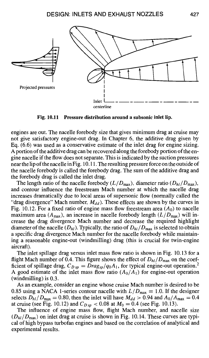
Fig. 10.11 Pressure distribution around a subsonic inlet lip.
engines are out. The nacelle forebody size that gives minimum drag at cruise may
not give satisfactory engine-out drag. In Chapter 6, the additive drag given by
Eq. (6.6) was used as a conservative estimate of the inlet drag for engine sizing.
A portion of the additive drag can be recovered along the forebody portion of the en-
gine nacelle if the flow does not separate. This is indicated by the suction pressures
near the lip of the nacelle in Fig. 10.11. The resulting pressure force on the outside of
the nacelle forebody is called the forebody drag. The sum of the additive drag and
the forebody drag is called the inlet drag.
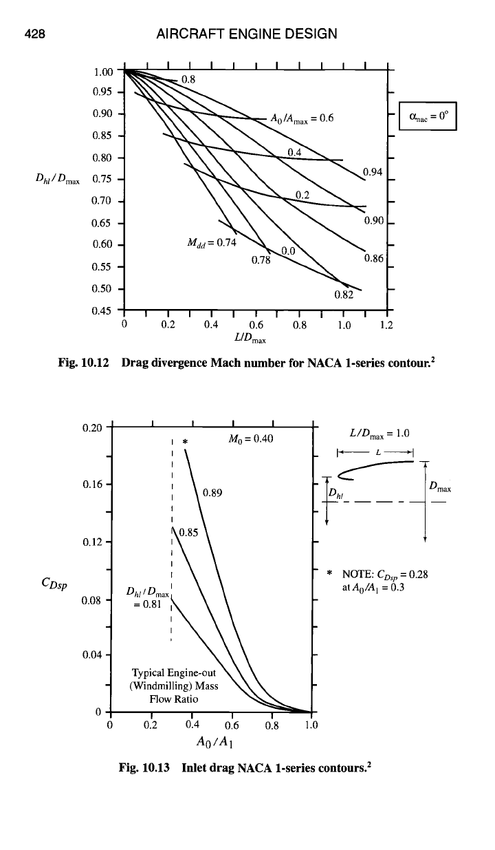
The length ratio of the nacelle forebody
(L/Dmax),
diameter ratio
(Dhl/Dmax),
and contour influence the freestream Mach number at which the nacelle drag
increases dramatically due to local areas of supersonic flow (normally called the
"drag divergence" Mach number,
Maa).
These effects are shown by the curves in
Fig. 10.12. For a fixed ratio of engine mass flow freestream area (A0) to nacelle
maximum area (Amax), an increase in nacelle forebody length
(L/Dmax)
will in-
crease the drag divergence Mach number and decrease the required highlight
diameter of the nacelle
(Dhl).
Typically, the ratio of
Dhl/Dmax
is selected to obtain
a specific drag divergence Mach number for the nacelle forebody while maintain-
ing a reasonable engine-out (windmilling) drag (this is crucial for twin-engine
aircraft).
The inlet spillage drag versus inlet mass flow ratio is shown in Fig. 10.13 for a
flight Mach number of 0.4. This figure shows the effect of
Dhl/Omax
on
the coef-
ficient of spillage drag,
CDsp = Dragsp/qoA1,
for typical engine-out operation. 2
A good estimate of the inlet mass flow ratio
(Ao/A1)
for engine-out operation
(windmilling) is 0.3.
As an example, consider an engine whose cruise Mach number is desired to be
0.85 using a NACA 1-series contour nacelle with
L/Dmax
= 1.0. If the designer
selects
Dhl/Drnax
= 0.80, then the inlet will have M~a > 0.94 and
Ao/Amax
-= 0.4
at cruise (see Fig. 10.12) and
Cow
< 0.08 at M0 = 0.4 (see Fig. 10.13).
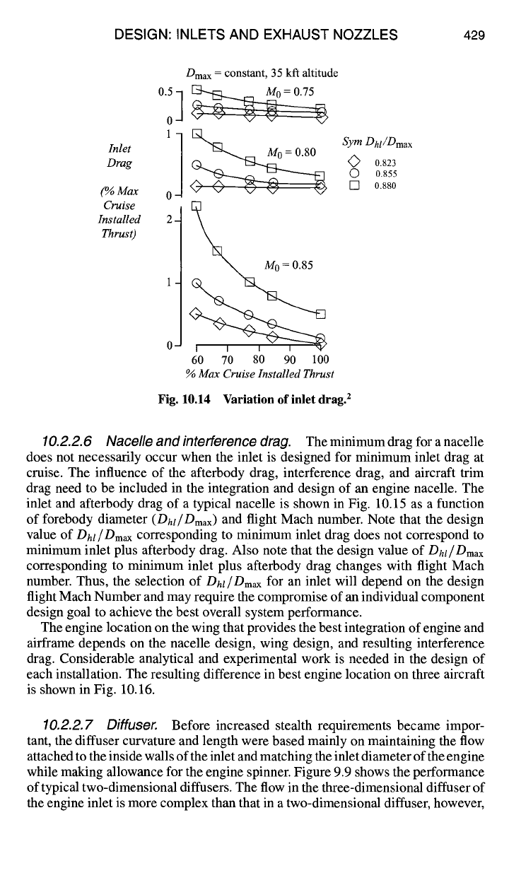
The influence of engine mass flow, flight Mach number, and nacelle size
(Dhl/Dmax)
on
inlet drag at cruise is shown in Fig. 10.14. These curves are typi-
cal of high bypass turbofan engines and based on the correlation of analytical and
experimental results.
428 AIRCRAFT ENGINE DESIGN
Dhl/Dmax
0.55
0.50
0.45
1.00 [
I I I I I I I I I I I
I
0.95
0.90
Ao/Ama x
= 0.6
0.85
o8o_ <~,'-~
075 ~~094
0.70 ~~
0.65 ~0.90
0.60
0.78 ~ 0.86
0.82
I I I I I I I I I I
0 0.2 0.4 0.6 0.8 1.0
L[Omax
Fig. 10.12
~,ac = oo I
1.2
Drag divergence Mach number for NACA 1-series contour. 2
CDw
0.20
0.16
0.12
0.08
0.04
I
I
I I
, M o = 0.40
0.89
TypicalEngine-out
\\ \
(Windmilling) Mass
\\\
0.2 0.4 0.6 0.8 1.0
Ao/A1
L/Dma x = 1.0
I" L "l
NOTE:
CDs p
= 0.28
atAo/A 1
= 0.3
Fig. 10.13 Inlet drag NACA 1-series contours. 2
DESIGN: INLETS AND EXHAUST NOZZLES 429
Dma x =
constant, 35 kfl altitude
Inlet 11~ SymDhl/Dmax
Drag
0<~ 0.823
0.855
(%Max
0 ~ @ ~ [] o.880
Cruise
M 0 = 0.85
Installed 2 -
Thrust)
o
60 70 80 90 100
% Max Cruise Installed Thrust
Fig. 10.14 Variation of inlet drag. 2
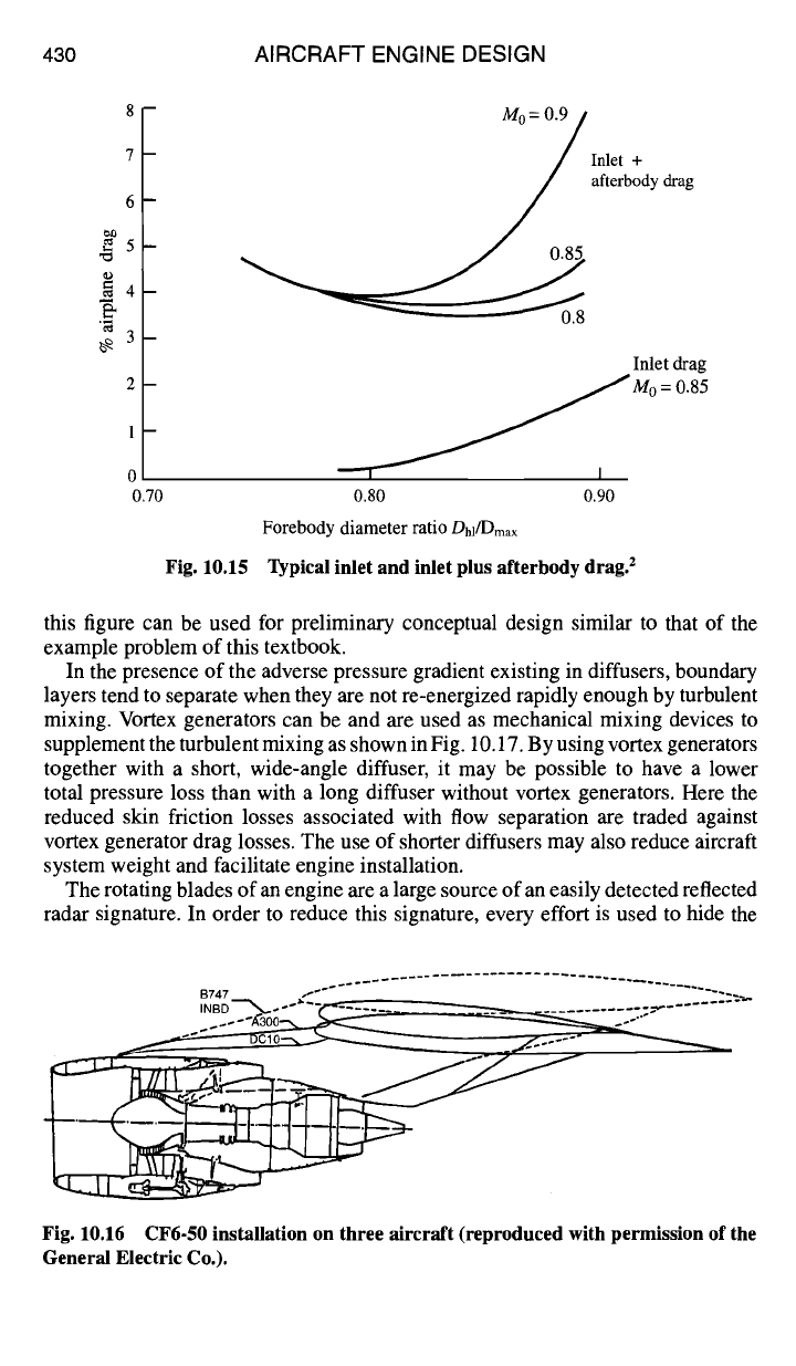
10.2.2.6 Nacelle and interference drag.
The minimum drag for a nacelle
does not necessarily occur when the inlet is designed for minimum inlet drag at
cruise. The influence of the afterbody drag, interference drag, and aircraft trim
drag need to be included in the integration and design of an engine nacelle. The
inlet and afterbody drag of a typical nacelle is shown in Fig. 10.15 as a function
of forebody diameter
(Dhl/Dmax)
and flight Mach number. Note that the design
value of
Dhl/Dmax
corresponding to minimum inlet drag does not correspond to
minimum inlet plus afterbody drag. Also note that the design value of
Dhl/Dmax
corresponding to minimum inlet plus afterbody drag changes with flight Mach
number. Thus, the selection of
Dhl/Dmax
for an inlet will depend on the design
flight Mach Number and may require the compromise of an individual component
design goal to achieve the best overall system performance.
The engine location on the wing that provides the best integration of engine and
airframe depends on the nacelle design, wing design, and resulting interference
drag. Considerable analytical and experimental work is needed in the design of
each installation. The resulting difference in best engine location on three aircraft
is shown in Fig. 10.16.
10.2.2. 7 Diffuser.
Before increased stealth requirements became impor-
tant, the diffuser curvature and length were based mainly on maintaining the flow
attached to the inside walls of the inlet and matching the inlet diameter of the engine
while making allowance for the engine spinner. Figure 9.9 shows the performance
of typical two-dimensional diffusers. The flow in the three-dimensional diffuser of
the engine inlet is more complex than that in a two-dimensional diffuser, however,
430 AIRCRAFT ENGINE DESIGN
8 m
7-
6-
~= 5-
==4-
3-
2-
1-
~.70
Fig. 10.15
~ Inlet +
afterbody drag
. /
0.85
Inlet drag
~~/,~I M0
=
0.85
0.80 0.90
Forebody diameter ratio Dhl/Dmax
Typical inlet and inlet plus afterbody drag. 2
this figure can be used for preliminary conceptual design similar to that of the
example problem of this textbook.
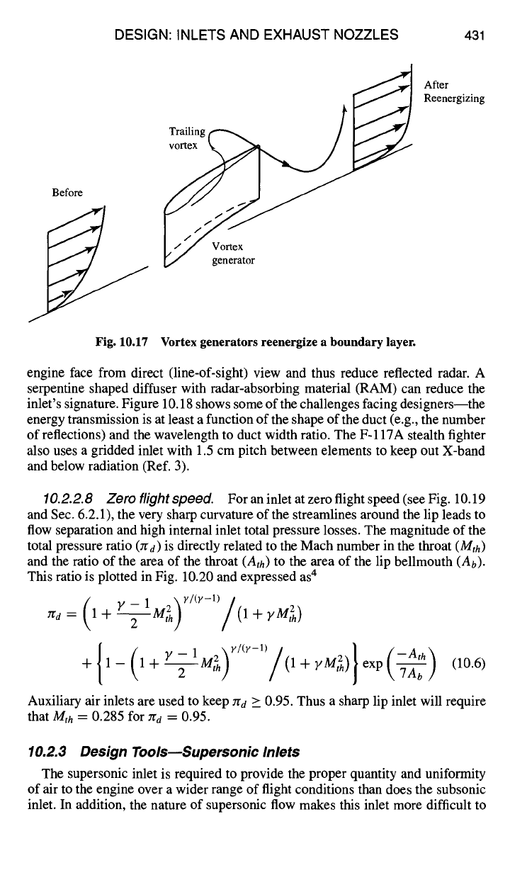
In the presence of the adverse pressure gradient existing in diffusers, boundary
layers tend to separate when they are not re-energized rapidly enough by turbulent
mixing. Vortex generators can be and are used as mechanical mixing devices to
supplement the turbulent mixing as shown in Fig. 10.17. By using vortex generators
together with a short, wide-angle diffuser, it may be possible to have a lower
total pressure loss than with a long diffuser without vortex generators. Here the
reduced skin friction losses associated with flow separation are traded against
vortex generator drag losses. The use of shorter diffusers may also reduce aircraft
system weight and facilitate engine installation.
The rotating blades of an engine are a large source of an easily detected reflected
radar signature. In order to reduce this signature, every effort is used to hide the
Fig. 10.16 CF6-50 installation on three aircraft (reproduced with permission of the
General Electric Co.).
DESIGN: INLETS AND EXHAUST NOZZLES 431
Before
I
/
/~ After
Reenergizing
Trailing
y generator
Fig. 10.17 Vortex generators reenergize a boundary layer.
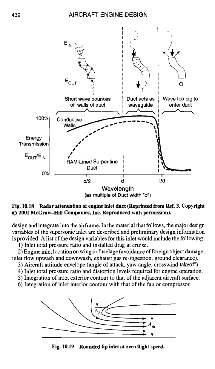
engine face from direct (line-of-sight) view and thus reduce reflected radar. A
serpentine shaped diffuser with radar-absorbing material (RAM) can reduce the
inlet's signature. Figure 10.18 shows some of the challenges facing designers the
energy transmission is at least a function of the shape of the duct (e.g., the number
of reflections) and the wavelength to duct width ratio. The F-117A stealth fighter
also uses a gridded inlet with 1.5 cm pitch between elements to keep out X-band
and below radiation (Ref. 3).
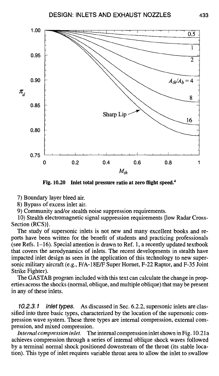
10.2.2.8 Zero flight speed.
Foraninletatzeroflightspeed(seeFig. 10.19
and Sec. 6.2.1), the very sharp curvature of the streamlines around the lip leads to
flow separation and high internal inlet total pressure losses. The magnitude of the
total pressure ratio (red) is directly related to the Mach number in the throat (Mth)
and the ratio of the area of the throat (Ath) to the area of the lip bellmouth (Ab).
This ratio is plotted in Fig. 10.20 and expressed as 4
(1+ Y-1 2\ ×~(v-l) I
2 /(1
red
N
{ ( )×'(×-')/ } (--Atk) (10.6)
+ 1- 1+ V-2 1Mr ~ (l+YMt~) exp\--~b]
Auxiliary air inlets are used to keep rea >__ 0.95. Thus a sharp lip inlet will require
that Mth = 0.285 for red = 0.95.
10.2.3 Design Tools--Supersonic Inlets
The supersonic inlet is required to provide the proper quantity and uniformity
of air to the engine over a wider range of flight conditions than does the subsonic
inlet. In addition, the nature of supersonic flow makes this inlet more difficult to
432 AIRCRAFT ENGINE DESIGN
100%
Energy
Transmission
Eou-r/EIN
0%
EIN "--.
EOUT~
e
r
Shod wave bounces
off
walls of duct
A
J
/
~ ')
Duct acts as
waveguide
A
Conductive ~ I., .... "~
sss S
I !
S
S
/
#
I
/
RAM-Lined Serpentine
Duct
Fig. 10.18
© 2001 McGraw-Hill Companies, Inc. Reproduced with permission).
/
Z
Wave too big to
enter duct
/ \
I
d/2 d 2d
Wavelength
(as multiple of Duct width "d")
Radar attenuation of engine inlet duct (Reprinted from Ref. 3. Copyright
design and integrate into the airframe. In the material that follows, the major design
variables of the supersonic inlet are described and preliminary design information
is provided. A list of the design variables for this inlet would include the following:
1) Inlet total pressure ratio and installed drag at cruise.
2) Engine inlet location on wing or fuselage (avoidance of foreign object damage,
inlet flow upwash and downwash, exhaust gas re-ingestion, ground clearance).
3) Aircraft attitude envelope (angle of attack, yaw angle, crosswind takeoff).
4) Inlet total pressure ratio and distortion levels required for engine operation.
5) Integration of inlet exterior contour to that of the adjacent aircraft surface.
6) Integration of inlet interior contour with that of the fan or compressor.
Fig. 10.19 Rounded lip inlet at zero flight speed.
DESIGN: INLETS AND EXHAUST NOZZLES 433
1.00
0.85
0.80
0.75
0 0.2 0.4 0.6 0.8 1
Mth
Fig. 10.20 Inlet total pressure ratio at zero flight speed. 4
7) Boundary layer bleed air.
8) Bypass of excess inlet air.
9) Community and/or stealth noise suppression requirements.
10) Stealth electromagnetic signal suppression requirements {low Radar Cross-
Section (RCS)}.
The study of supersonic inlets is not new and many excellent books and re-
ports have been written for the benefit of students and practicing professionals
(see Refs. 1-16). Special attention is drawn to Ref. 1, a recently updated textbook
that covers the aerodynamics of inlets. The recent developments in stealth have
impacted inlet design as seen in the application of this technology to new super-
sonic military aircraft (e.g., F/A-18E/F Super Homet, F-22 Raptor, and F-35 Joint
Strike Fighter).
The GASTAB program included with this text can calculate the change in prop-
erties across the shocks (normal, oblique, and multiple oblique) that may be present
in any of these inlets.
10.2.3.1 Inlet types.
As discussed in Sec. 6.2.2, supersonic inlets are clas-
sified into three basic types, characterized by the location of the supersonic com-
pression wave system. These three types are internal compression, external com-
pression, and mixed compression.
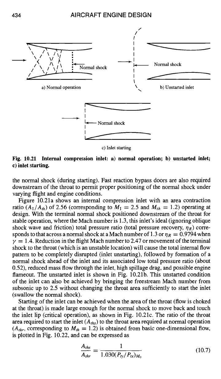
Internalcompression inlet.
The internal compression inlet shown in Fig. 10.21 a
achieves compression through a series of internal oblique shock waves followed
by a terminal normal shock positioned downstream of the throat (its stable loca-
tion). This type of inlet requires variable throat area to allow the inlet to swallow
434 AIRCRAFT ENGINE DESIGN
/
/
\k /~ \\//\/
J
!,
_' Normal shock
|
a) Normal operation
\
Normal shock
b) Unstarted inlet
I
I ,~ Normal shock
I
I
c) Inlet starting
Fig.
10.21 Internal
compression inlet:
a) normal operation; b) unstarted inlet;
c) inlet starting.
the normal shock (during starting). Fast reaction bypass doors are also required
downstream of the throat to permit proper positioning of the normal shock under
varying flight and engine conditions.
Figure 10.21a shows an internal compression inlet with an area contraction
ratio (A1/Ath) of 2.56 (corresponding to M1 = 2.5 and Mth = 1.2) operating at
design. With the terminal normal shock positioned downstream of the throat for
stable operation, where the Mach number is 1.3, this inlet's ideal (ignoring oblique
shock wave and friction) total pressure ratio (total pressure recovery, r/n) corre-
sponds to that across a normal shock at a Mach number of 1.3 or OR = 0.9794 when
y = 1.4. Reduction in the flight Mach number to 2.47 or movement of the terminal
shock to the throat (which is an unstable location) will cause the total internal flow
pattern to be completely disrupted (inlet unstarting), followed by formation of a
normal shock ahead of the inlet and its associated low total pressure ratio (about
0.52), reduced mass flow through the inlet, high spillage drag, and possible engine
flameout. The unstarted inlet is shown in Fig. 10.2lb. This unstarted condition
of the inlet can also be achieved by bringing the freestream Mach number from
subsonic up to 2.5 without changing the throat area sufficiently to start the inlet
(swallow the normal shock).
Starting of the inlet can be achieved when the area of the throat (flow is choked
at the throat) is made large enough for the normal shock to move back and touch
the inlet lip (critical operation), as shown in Fig. 10.21c. The ratio of the throat
area required to start the inlet (Aths) to the throat area required at normal operation
(Athr, corresponding to Mth = 1.2) is obtained from basic one-dimensional flow,
is plotted in Fig. 10.22, and can be expressed as
Ath s 1
= (10.7)
Athr 1.030(Pty/Ptx)Mo
DESIGN: INLETS AND EXHAUST NOZZLES 435
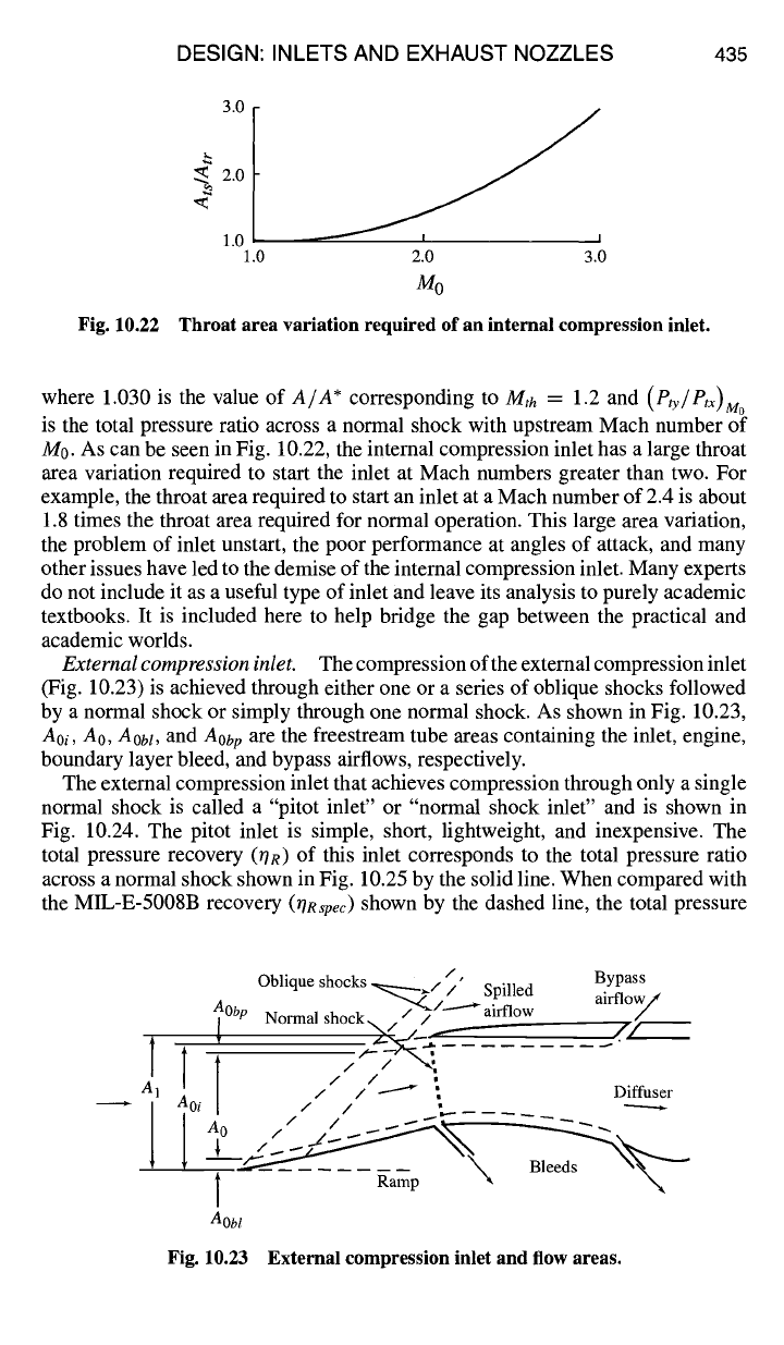
Fig. 10.22
3.0
.~ 2.0
1.0
1.0 2.0 3.0
M0
Throat area variation required of an internal compression inlet.
where 1.030 is the value of
A/A*
corresponding to Mth
=
1.2 and
(Pty/Ptx)M °
is the total pressure ratio across a normal shock with upstream Mach number of
M0. As can be seen in Fig. 10.22, the internal compression inlet has a large throat
area variation required to start the inlet at Mach numbers greater than two. For
example, the throat area required to start an inlet at a Mach number of 2.4 is about
1.8 times the throat area required for normal operation. This large area variation,
the problem of inlet unstart, the poor performance at angles of attack, and many
other issues have led to the demise of the internal compression inlet. Many experts
do not include it as a useful type of inlet and leave its analysis to purely academic
textbooks. It is included here to help bridge the gap between the practical and
academic worlds.
External compression inlet.
The compression of the external compression inlet
(Fig. 10.23) is achieved through either one or a series of oblique shocks followed
by a normal shock or simply through one normal shock. As shown in Fig. 10.23,
Aoi, AO, AObl,
and
Aob p are
the freestream tube areas containing the inlet, engine,
boundary layer bleed, and bypass airflows, respectively.
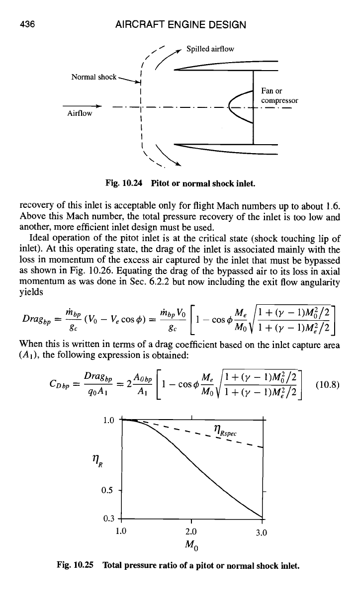
The external compression inlet that achieves compression through only a single
normal shock is called a "pitot inlet" or "normal shock inlet" and is shown in
Fig. 10.24. The pitot inlet is simple, short, lightweight, and inexpensive. The
total pressure recovery (OR) of this inlet corresponds to the total pressure ratio
across a normal shock shown in Fig. 10.25 by the solid line. When compared with
the MIL-E-5008B recovery
(OR~pec)
shown by the dashed line, the total pressure
/t
Oblique shocks ~.// Spilled Bypass
airflow
j v Normal shock__//.,,, / ....... /
f -
, ,...--- //
,_____ ---'~__-_: ......
A1 a / / / I Diffuser
I
-- ""
Ramp
Aobl
Fig. 10.23 External compression inlet and flow areas.
436 AIRCRAFT ENGINE DESIGN
///~.....Spilled airflow
Normal shock
Airflow
Fan or
.~._ compressor
Fig. 10.24 Pitot or normal shock inlet.
recovery of this inlet is acceptable only for flight Mach numbers up to about 1.6.
Above this Mach number, the total pressure recovery of the inlet is too low and
another, more efficient inlet design must be used.
Ideal operation of the pitot inlet is at the critical state (shock touching lip of
inlet). At this operating state, the drag of the inlet is associated mainly with the
loss in momentum of the excess air captured by the inlet that must be bypassed
as shown in Fig. 10.26. Equating the drag of the bypassed air to its loss in axial
momentum as was done in Sec. 6.2.2 but now including the exit flow angularity
yields
M e
/1 +(y-1)M2/21
Dragbp
= rhbp (V0- Vecos4,) =
thbpVo
1-cos4,-77-, ,/]MoV
gc gc + (y
1)Me2/2 J
When this is written in terms of a drag coefficient based on the inlet capture area
(A1), the following expression is obtained:
Dragbp Aobp[ --~oo~ I+(Y-1)M~/211)M~/2J
-- -- -- 2 1 -- cos 4' ~. (10.8)
CDbp
qoAl A1 1
+
(y
1.0 I
0.3 I
1.0 2.0 3.0
M0
Total pressure ratio of a
pitot or normal shock
inlet.
%
0.5
Fig. 10.25