Middleton W.M. (ed.) Reference Data for Engineers: Radio, Electronics, Computer and Communications
Подождите немного. Документ загружается.

41-10
REFERENCE
DATA
FOR
ENGINEERS
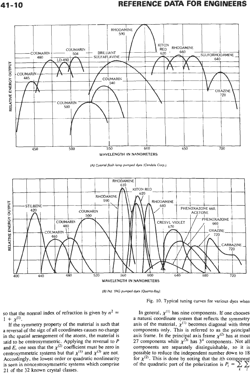
(A)
Coaxla1
flash
lomp pumped dyes (Condelo Corp.)
WAVELENGTH IN NANOMETERS
(Bj
Nd:
YAG
pumped dyes
(Quonto-Ray)
so
that the normal index of refraction is given by
n2
=
If the symmetry property of the material is such that
a
reversal of the sign of all coordinates causes no change
in the spatial arrangement of the atoms, the material is
said to be centrosymmetric. Applying the reversal to
P
and
E,
one sees that the
x(~)
coefficient must be zero in
centrosymmetric systems but that
x(I)
and
x(3)
are not.
Accordingly, the lowest order or quadratic nonlinearity
is seen in noncentrosymmetric systems which comprise
21
of the
32
known crystal classes.
1
+
x(1'.
Fig.
10.
Typical
tuning
curves
for
various
dyes
when
In general,
x(')
has nine components. If one chooses
a natural coordinate system that reflects the symmetry
axis
of
the material,
x(')
becomes diagonal with three
components only. This is referred to as the principal
axis frame. In the princi a1
axis
frame
x(~)
has at most
components are separately distinguishable,
so
it is
possible to reduce the independent number down
to
18
for
x(~).
This
is
done by noting that the ith component
of the quadratic
part
of
the polarization is
4
=
2 2
27
components while
,y(
P
)
has
34
components.
Not
all
ki
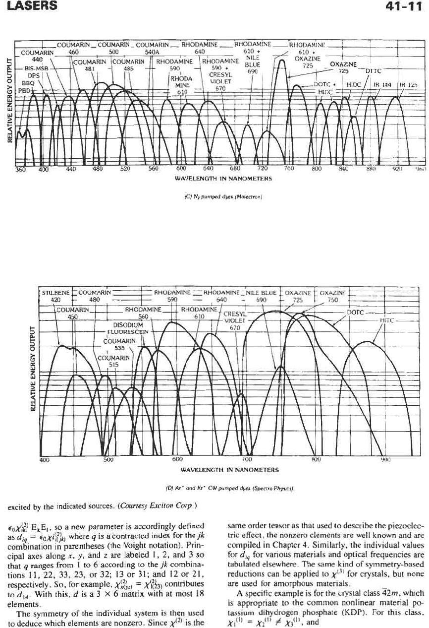
LASERS
41-11
WAVELENGTH IN NANOMETERS
(C)
Nz
pumped
dyer
(Molectron)
WAVELENGTH IN NANOMETERS
(D)
Art
and
Kr*
CW
pumped dyes
(Spectra-Physics)
excited
by
the
indicated
sources.
(Courtesy
Exciton
Corp.)
q,x$2)
E,E,
,
so
a new parameter is accordingly defined
as
di,
=
~~xif)~)
where
q
is a contracted index for the
jk
combination in parentheses (the Voight notation). Prin-
cipal axes along
x,
y,
and
z
are labeled
1,
2,
and
3
so
that
q
ranges from 1 to
6
according to the
jk
combina-
tions 11, 22,
33,
23, or 32;
13
or 31; and 12 or 21,
respectively.
So,
for example,
x$iz)
=
x\&)
contributes
to
did.
With this,
d
is a
3
X
6
matrix with at most
18
elements.
The symmetry
of
the individual system is then used
to deduce which elements are nonzero. Since
x(')
is the
same order tensor as that used to describe the piezoelec-
tric effect, the nonzero elements are well known and are
compiled in Chapter
4.
Similarly, the individual values
ford,, for various materials and optical frequencies are
tabulated elsewhere. The same kind of symmetry-based
reductions can be applied
to
x'~'
for crystals, but none
are used
for
amorphous materials.
A
specific example is for the crystal class
52m,
which
is appropriate to the common nonlinear material po-
tassium dihydrogen phosphate
(KDP).
For
this class,
xi(')
=
xii)
#
x3('),
and
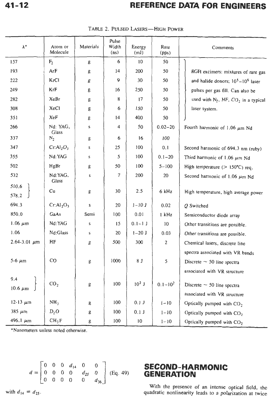
41-12
REFERENCE
DATA
FOR ENGINEERS
TABLE
2.
PULSED
LASERS-HIGH
POWER
A*
157
193
222
249
282
308
35
1
266
337
347
355
502
532
510.6
578.2
694.3
850.0
1.06
pm
1.06
2.64-3.01
pm
5-6
pm
9'4
10.6
pm
1
12-13
pm
385
pm
496.1
pin
Atom
or
Molecule
s
4rF
KICl
KrF
XeBr
XeCl
XeF
Nd: YAG,
Glass
N2
Cr:AI203
Nd:YAG
HgBr
Nd
:
YAG,
Glass
cu
Cr:A1,03
GaAs
Nd:YAG
Nd:Glass
HF
co
CO2
NH3
D20
CH,F
Materials
*Nanometers unless noted otherwise.
-
Pulse
Width
(ns)
6
14
9
16
8
6
14
4
6
25
5
50
I
30
20
100
15
20
500
1000
100
100
100
100
-
Energy
(mJ)
10
200
30
250
17
150
400
50
16
100
100
100
200
2.5
1-10
J
0.01
0.1-1
J
1-20
J
300
85
IOz
J
0.1
J
0.1
J
10
50
50
50
50
50
50
50
3.02-20
100
0.1
0.1-20
5-100
20
6
kHz
0.02
1
kHz
10
0.03
2
5
0.1-102
1-10
1-10
1-10
Comments
RGH
excimers: mixtures
of
rare gas
and halide donors;
105-106
laser
pulses per gas
fill.
Can also be
used with
N2,
HF, C02 in a typical
laser system.
mrth harmonic
of
1.06
pn
Nd
econd harmonic
of
694.3
nm (ruby)
hird harmonic
of
1.06
pm
Nd
[igh temperature
(>
150'C)
req.
econd harmonic
of
1.06
pm
Nd
Iigh temperature, high average power
?
Switched
iemiconductor diode array
Ither transitions are possible.
Ither transitions are possible.
:hemica1 lasers, discrete line
,pectra associated with VR bands
liscrete
-
50
line spectra
issociated with VR structure
Discrete
-
50
line spectra
issociated with VR structure
Dptically pumped with C02
Optically pumped with COz
Optically pumped with COz
SECOND-HARMONIC
0%
49)
GENERATION
0000
0
d36
With the presence
of
an
intense optical field, the
quadratic nonlinearity leads
to
a polarization at twice
with
d14
=
d25.
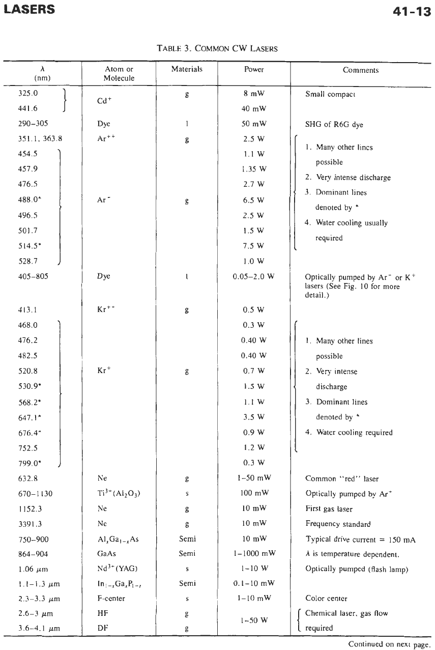
41-13
TABLE
3.
COMMON CW
LASERS
~
A
(nm)
325.0
441.6
290-305
351.1, 363.8
454.5
457.9
476.5
488
O*
496.5
501.7
514.5*
528.7
405-805
413.1
468.0
476.2
482.5
520.8
530.9%
568.2'
647.1*
676.4'
752.5
799.0*
632.8
670-
1
I30
1152.3
3391.3
750-900
864-904
1.06
pm
1.1-1.3
pm
2.3-3.3
pm
2.6-3
pm
3.6-4.1
pm
Atom
or
Molecule
Cdt
Dye
Arf+
Ar'
Kr+
Ne
Ti3+(AI203)
Ne
Ne
A1,Gal-,As
GaAs
Nd3' (YAG)
In,-,Ga,P,-,
F-center
HF
DF
Materials
Power
8
mW
40
mW
50
mW
2.5
W
1.1
w
1.35
W
2.7
W
6.5
W
2.5
W
1.5 W
7.5
w
1.0
w
0.05-2.0
W
0.5
W
0.3
W
0.40
W
0.40
W
0.7
W
1.5 W
1.1
w
3.5
w
0.9
W
1.2
w
0.3
W
1-50
mW
100
mW
10
mW
10
mW
10
mW
1-1000
mW
1-10
w
0.1-10
mW
1-10 mW
1-50
W
Comments
Small compact
SHG
of
R6G
dye
1.
Many other lines
possible
2. Very intense discharge
3.
Dominant lines
denoted by
*
4.
Water cooling usually
required
Optically pumped by
Ar'
or
K+
lasers (See Fig.
10
for
more
detail.)
1.
Many other lines
possible
2.
Very intense
discharge
3.
Dominant lines
denoted by
*
4.
Water cooling required
Common "red" laser
Optically pumped by Art
First gas laser
Frequency standard
Typical drive current
=
150
mA
A
is temperature dependent.
Optically pumped (flash lamp)
Color center
Chemical laser, gas flow
required
Continued on next page.
41-14
Atom
or
Molecule
co
COZ
co2
H20
CH,OH
HCN
CH,F
REFERENCE
DATA
FOR ENGINEERS
Materials
g
g
g
g
g
g
g
h
(nm)
5-6.5
pm
9.2-11.2
pm
10.6
pm
28, 78, 118
pm
118.1
pm
311, 377
pm
496.1
un
1.4
-
12
-
g
1.0
-
?
3
’
0.8
-
2
0.6
-
+
2
2
0.4
-
0
0.2
-
TABLE
3
(CONT).
COMMON
CW
LASERS
Power
10-20
w
4w
50 W-8.5
kW
10 mW
100
mW
100
mW
25
mW
Comments
Line
selectable
Line selectable, sealed
Flowing gas
Electrically excited
Optically pumped
(See
Fig.
12.)
Electrically excited
Optically pumped with COz
650
700 800
900
1000
1100
1200
WAVELENGTH IN NANOMETERS
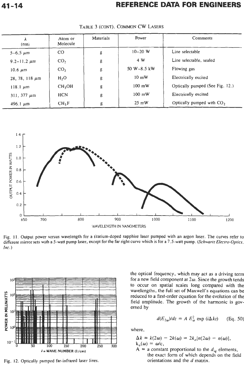
Fig. 11. Output power versus wavelength for
a
titatium-doped sapphire laser pumped with an argon laser. The curves refer to
different mirror sets with a 5-watt pump laser, except for the far right curve which
is
for a 7.5-watt pump.
(SchwurrzElectro-Optics,
Inc.)
i=
WAVE
NUMBER
(l/cm)
Fig.
12.
Optically pumped far-infrared laser lines.
the optical frequency, which may act as a driving term
for a new field component at
2w.
Since the growth tends
to occur
on
spatial scales long compared with the
wavelengths, the
full
set
of
Maxwell’s
equations
can
be
reduced to a first-order equation for the evolution
of
the
field amplitude. The growth of the harmonic is gov-
erned
by
d(E,,)/dz
=
A
E;
exp
(iAkz)
(Eq.
50)
where,
Ak
=
k(2w)
-
2k(w)
=
2k0[n(20)
-
n(w)],
k,(o)
=
wtc,
A
=
a constant proportional to the
d,
elements,
the exact
form
of
which depends on the field
orientations and the
d
matrix.
LASERS
I
I
d
41-15
I
I
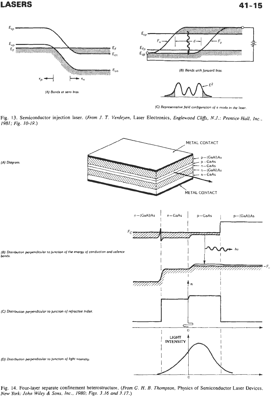
(A)
Bands at zero bras.
(5) Bands wlth forward
blas
(C)
Representatiw field configuratlon
of
(i
mode
In
the
laser.
Fig.
13.
Semiconductor injection laser.
(From
J.
T.
Verdeyen,
Laser Electronics,
Englewood
Clifs,
N.J.:
Prentice-Hull,
Inc.,
1981;
Fig.
10-19.)
METAL CONTACT
(A)
Dlagram
1
METAL CONTACT
n-(GaAI)As
I
n-GaAs
I
p-GaAs
1
p-(GaAI)As
I
(0
Dlstrlbutlon perpendlcular to lunctlon
of
refractlue Index
LIGHT
I
I
-I
I
INTENSITY
(0)
Dlstrlbutlon perpendlcular to junctlon
of
lfght lntenslty.
Fig.
14.
Four-layer separate confinement heterostructure.
(From
G.
H.
E.
Thompson,
Physics
of
Semiconductor Laser Devices.
New
York:
John
Wiley
&
Sons,
Inc.,
1980;
Figs.
3.16
and
3.17.)
41-16
REFERENCE
DATA
FOR
ENGINEERS
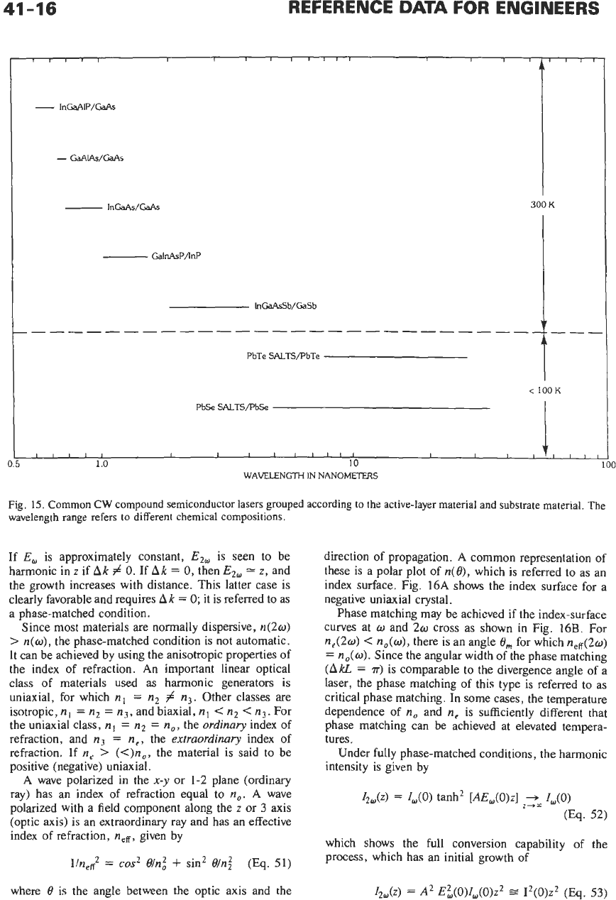
300
K
<
100
K
IIIII
f
I
I I I I,,, I I
,
,I,
,
,
,
PbSe
SALTSPbSe
1.0
10
WAVELENGTH
IN
NANOMEl€RS
Fig.
15.
Common
CW
compound semiconductor lasers grouped according to the active-layer material
and
substrate material. The
wavelength range refers
to
different chemical compositions.
If
E,
is approximately constant,
E2w
is seen to be
harmonic in
z
if
Ak
#
0.
If
Ak
=
0,
then
E2@
=
z,
and
the growth increases with distance. This latter case is
clearly favorable and requires
Ak
=
0;
it
is
referred to as
a phase-matched condition.
Since
most
materials are normally dispersive,
420)
>
n(o),
the phase-matched condition is not automatic.
It can be achieved by using the anisotropic properties of
the index of refraction.
An
important linear optical
class of materials used as harmonic generators is
uniaxial, for which
nl
=
n2
#
n3.
Other classes are
isotropic,
nl
=
n2
=
n3,
and biaxial,
nl
<
n2
<
n3.
For
the uniaxial class,
n,
=
n2
=
no,
the
ordinary
index of
refraction, and
n3
=
ne,
the
extraordinary
index of
refraction. If
ne
>
(<)no,
the material is said to be
positive (negative) uniaxial.
A
wave polarized in the
x-y
or
1-2
plane (ordinary
ray) has an index of refraction equal to
no.
A wave
polarized with a field component along the
z
or
3
axis
(optic axis)
is
an extraordinary ray and has an effective
index of refraction,
neff,
given by
lln,;
=
cos2
Oh:
+
sin2
Oh$
(Eq.
51)
where
0
is the angle between the optic axis and the
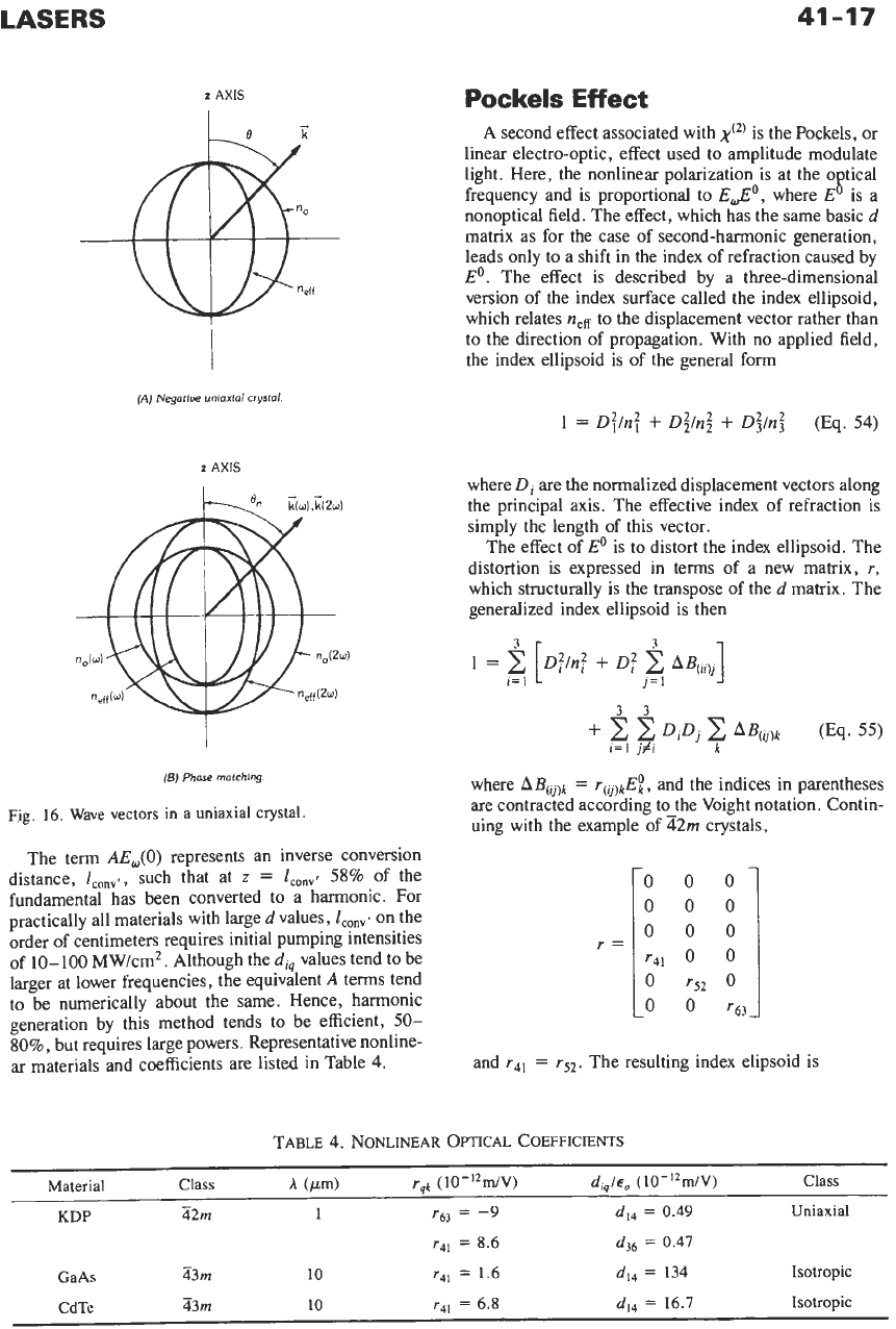
direction of propagation. A common representation of
these is a polar plot of
n(O),
which is referred to as an
index surface. Fig. 16A shows the index surface for a
negative uniaxial crystal.
Phase matching may be achieved if the index-surface
curves at
o
and
20
cross as shown in Fig. 16B. For
n,(2o)
<
n,(w),
there is an angle
e,,,
for which
neff(20)
=
no(@).
Since the angular width of the phase matching
(AkL
=
?r)
is comparable
to
the divergence angle of a
laser, the phase matching
of
this type
is
referred to as
critical phase matching.
In
some cases, the temperature
dependence
of
no
and
n,
is sufficiently different that
phase matching can be achieved at elevated tempera-
tures.
Under fully phase-matched conditions, the harmonic
intensity is given by
which shows the full conversion capability of the
process, which has an initial growth of
LASERS
41-17
z
AXIS
(A)
Negotlue
unioxlai
crystal.
3
i=l
j=
1
(B)
Phase
rnntchlng.
Fig.
16.
Wave vectors in
a
uniaxial crystal.
The term
AEJO)
represents an inverse conversion
distance,
l,,,,.,
such that at
z
=
lc0,,~
58%
of the
fundamental has been converted to a harmonic. For
practically all materials with large
d
values,
Z,,,,
on the
order
of
centimeters requires initial pumping intensities
of 10-100 MW/cm2. Although the
di,
values tend to be
larger at lower frequencies, the equivalent
A
terms tend
to be numerically about the same. Hence, harmonic
generation by this method tends to be efficient,
50-
80%,
but requires large powers. Representative nonline-
ar materials and coefficients are listed in Table
4.
Pockels
Effect
A
second effect associated with
is the Pockels, or
linear electro-optic, effect used to amplitude modulate
light. Here, the nonlinear polarization is at the
o
tical
nonoptical field. The effect, which has the same basic
d
matrix as for the case of second-harmonic generation,
leads only
to
a shift in the index of refraction caused by
Eo.
The effect is described by a three-dimensional
version of the index surface called the index ellipsoid,
which relates
nefi
to
the displacement vector rather than
to the direction of propagation. With no applied field,
the index ellipsoid is
of
the general form
frequency and is proportional to
E,,,Eo,
where E
!.
IS
a
where
Di
are the normalized displacement vectors along
the principal axis. The effective index of refraction
is
simply the length
of
this vector.
The effect of
Eo
is to distort the index ellipsoid. The
distortion
is
expressed in terms
of
a new matrix,
r,
which structurally is the transpose of the
d
matrix. The
generalized index ellipsoid is then
where
bB(ij,k
=
r(v)kF!,
and the indices in parentheses
are contracted according to-the Voight notation. Contin-
uing with the example
of
42m
crystals,
and
r41
=
r5*.
The resulting index elipsoid is
TABLE
4.
NONLINEAR OPTICAL
COEFFICIENTS
Material Class
h
(pm)
rqk
(10-'~miV)
diqlq,
(IO-12miV)
Class
-
KDP
42m
1
r63
=
-9
d14
=
0.49
Uniaxial
r4]
=
8.6
d,,
=
0.47
-
GaAs
43m
10
r41
=
1.6
d,,
=
134
Isotropic
CdTe
Z3m
10
~41
=
6.8
dI4
=
16.7
Isotropic
41-18
REFERENCE
DATA
FOR ENGINEERS
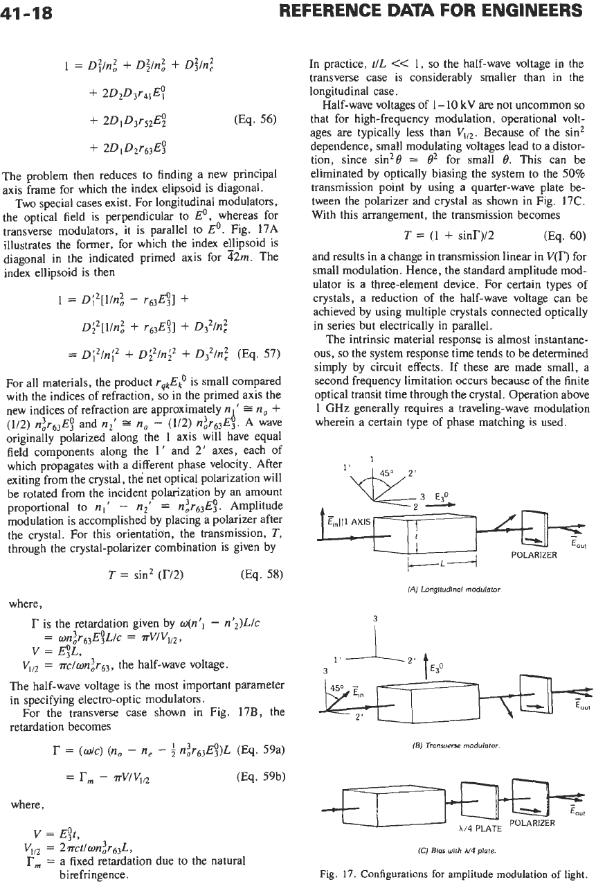
The problem then reduces to finding a new principal
axis frame for which the index elipsoid is diagonal.
Two special cases exist. For longitudinal modulators,
the optical field is perpendicular to
Eo,
whereas for
transverse modulators, it is parallel to
Eo.
Fig. 17A
illustrates the former, for which the index ellipsoid is
diagonal in the indicated primed axis for
42m.
The
index ellipsoid is then
1
=
Di2[l/n;
-
r63Eg]
f
D;’[l/n:
+
r63E!]
+
D:ln?
=
Di2/ni2
+
D;2/ni2
+
D32/n?
(Eq.
57)
For all materials, the product
rqkE:
is
small compared
with the indices of refraction,
so
in the primed axis the
new indices of refraction
are
approximately
n
’
(112) n:r6,E;
and
n2’
=
no
-
(112) n2r63E3.
A wave
originally polarized along the
1
axis will have equal
field components along the
1’
and
2’
axes, each
of
which propagates with a different phase velocity. After
exiting from the crystal, the net optical polarization will
be rotated from the incident polarization by an amount
proportional to
n,‘
-
n2‘
=
nar~~E2.
Amplitude
modulation is accomplished by placing a polarizer after
the crystal. For this orientation, the transmission,
T,
through the crystal-polarizer combination is given by
T
=
sin2
(r12)
(Eq.
58)
b
=no+
In practice,
tlL
<<
1,
so
the half-wave voltage in the
transverse case is considerably smaller than in the
longitudinal case.
Half-wave voltages of
1
-
10
kV
are not uncommon
so
that for high-frequency modulation, operational volt-
ages are typically less than Because of the sin2
dependence, small modulating voltages lead to a distor-
tion, since sin2@
=
0’
for small
t?.
This can be
eliminated by optically biasing the system to the
50%
transmission point by using a quarter-wave plate be-
tween the polarizer and crystal as shown in Fig.
17C.
With this arrangement, the transmission becomes
T
=
(1
+
sinr)/2
(Eq.
60)
and results in a change in transmission linear in
V(r)
for
small modulation. Hence, the standard amplitude mod-
ulator is a three-element device. For certain types of
crystals, a reduction
of
the half-wave voltage can be
achieved by using multiple crystals connected optically
in series but electrically in parallel.
The intrinsic material response is almost instantane-
ous,
so
the system response time tends to be determined
simply by circuit effects. If these are made small, a
second frequency limitation occurs because of the finite
optical transit time through the crystal. Operation above
1
GHz generally requires a traveling-wave modulation
wherein a certain type of phase matching is used.
POLARIZER
(A)
Longftudlnol
modulator
where,
r
is the retardation given by
o(nII
-
n’2)L/c
VI,,
=
riIon:rs3,
the half-wave voltage.
The half-wave voltage is the most important parameter
in specifying electro-optic modulators.
For the transverse case shown in Fig.
17B,
the
retardation becomes
r
=
(o/c)
(no
-
n,
-
$
n:r6&)~
(~q.
59a)
(Eq.
59b)
=
rm
-
rvlv,,,
where,
V
=
E;t,
v,,,
=
2~ct/onjr~~~,
Tm
=
a fixed retardation due to the natural
birefringence.
3
3
1’
J.
2’ f40
(B)
Transverse
rnodulotor
(CJ
Blas
with
U4
plate.
Fig.
17.
Configurations
for
amplitude modulation
of
light.
41-19
If the incident optical field is oriented along the
primed principal axis,
no
rotation of the polarization
occurs, but modulation of the phase velocity exists. By
this method, phase modulation may be achieved.
Stimulated Raman Emission
There are many other different effects associated with
x@)
and
x(3)
nonlinearities depending
on
the number of
different fields present. Frequency tripling into the dee
is significant. Similarly, another third-order effect leads
to a self-induced index of refraction change and causes
focusing and defocusing
of
a beam by virtue of its radial
intensity variation.
One important
x(~)
effect used to frequency shift light
is the stimulated Raman effect. Here, a polarization and
hence a gain is created at frequency
o'
due to a strong
field at
o
where
fio
-
fid
=
AE,
a characteristic
atomic or molecular energy, typically a vibrational
energy in a molecule. The interaction can also be
viewed as an inelastic scattering process wherein the
shift is determined by the characteristic energy. It is
possible to have stimulated rotational, vibrational, and
electronic Raman scattering with shifts ranging from a
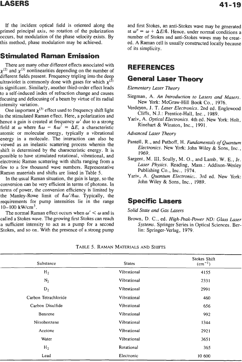
few to a few thousand wave numbers. Representative
Raman materials and shifts are listed in Table
5.
In
the usual Raman situation, the gain is large,
so
the
conversion can be very efficient in terms
of
photons. In
terms of power, the conversion efficiency is limited by
the Manley-Rowe limit of
fiw'lho.
Typically, the
requirements for pump intensities lie in the range
10-
100
kW/cm3.
The normal Raman effect occurs when
w'
<
o
and
is
called a Stokes wave. The growing first Stokes can reach
a sufficient intensity to act as a pump for a second
Stokes, and
so
on.
With the presence of astrong pump
ultraviolet is commonly done with gases for which
,y(
s
)
and first Stokes, an anti-Stokes wave may be generated
at
o"
=
o
+
AElfi.
Hence, under normal conditions a
number of Stokes and anti-Stokes waves may be creat-
ed. A Raman cell is usually constructed locally because
of
its simplicity.
REFERENCES
General Laser Theory
Elementary Laser Theory
Siegman,
A.
An Introduction to Lasers and Masers.
New York: McGraw-Hill Book
Co.,
1976.
Verdeyen,
J.
T.
Laser Electronics.
2nd ed. Englewood
Cliffs, N.J.: Prentice-Hall, Inc., 1989.
Yariv, A.
Optical Electronics.
4th ed. New York: Holt,
Rinehart
&
Winston, Inc., 1991.
Advanced Laser Theory
Pantell, R., and Puthoff,
H.
Fundamentals
of
Quantum
Electronics.
New York John Wiley
&
Sons, Inc.,
1969.
Sargent,
M.
111,
Scully, M.
O.,
and Lamb, W.
E.,
Jr.
Laser Physics.
Reading, Mass
.:
Addison-Wesley
Publishing Co., Inc., 1974.
Yariv, A.
Quantum Electronic.:.
3rd ed. New York:
John Wiley
&
Sons, Inc., 1989.
Specific
Lasers
Solid State and Gas Lasers
Brown,
D.
C., ed.
High-Peak-Power
ND:
Glass Laser
Systems.
Springer Series
in
Optical Sciences. Ber-
lin: Springer-Verlag, 1979.
TABLE
5.
RAMAN MATERIALS
AND
SHIFTS
~ ~~
Stokes
Shift
Substance
States
(cm-')
H2 Vibrational 4155
*2
Vibrational 2331
D2 Vibrational 2991
Carbon Tetrachloride
Vibrational 460
Carbon Disulfide
Vibrational 656
Benzene
Vibrational
992
Nitrobenzene Vibrational
1344
Acetone
Vibrational 292
1
Water
Vibrational 365
1
H2
Rotational 365
Lead Electronic
10
600