Morling K. Geometric and Engineering Drawing
Подождите немного. Документ загружается.

Geometric and Engineering Drawing174
Third angle projection
7
6,8
5,9
4,10
3,11
2,12
1
1
2
3
4
5
6
7
8
9
10
11
12
6,8
7
5,9
4,10
3,11
1
Sect 1
Sect 2,12
Sect 3,11
Sect 4,10
Sect 5,9
Sect 6,8
Sect 7
2,12
Sect 1
4
3,5
2,6
1,7
12,8
11,9
10
10'
11'
12'
1'
2'
3'
4'
5'
6'
7'
8'
9'
Sect 2,12
Sect 3,11
Sect 4,10
Sect 5,9
Sect 6,8
Sect 7
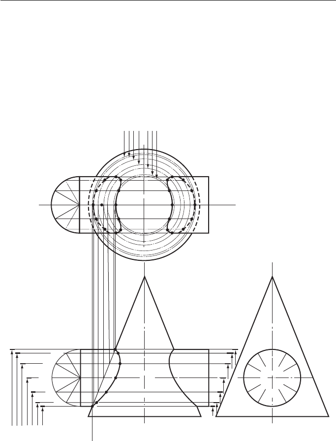
Figure 12.14
section. In this case, the section of the cone is a circle and the radius of that circle
is easily projected up to the plan. In Fig. 12.14 , the section is marked on the plan
as ‘ SECT 2,12 ’ and the exact position of point 2 is the intersection of that section
and the line marked 2,6. Point 12 is the intersection of the same section and the line
marked 12,8.
This process is repeated for each point in turn. When the plan is complete, the
points can be projected down to the FE; this is not shown for clarity.
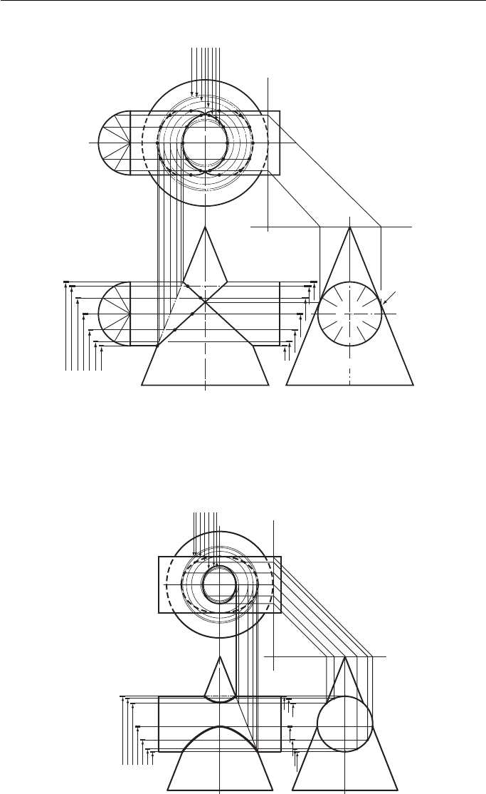
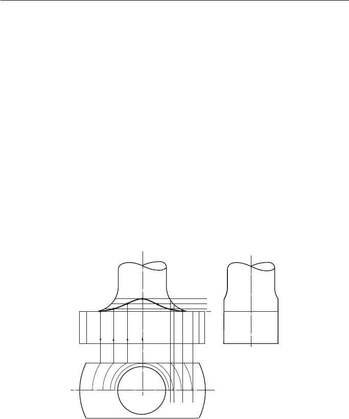
A cylinder and a cone, neither enveloping the other ( Fig. 12.15 ).
The constructions are exactly the same as those used in the previous example with
one small addition.
The EE shows a point of tangency between the cylinder and the cone. This point
is projected across to the FE and up to the plan as shown.
Intersection of Regular Solids 175
A cylinder and a cone, the cylinder enveloping the cone ( Fig. 12.16 ).
The construction required here is a modified version of the two previous ones.
Instead of the cylinder being divided into 12 equal sectors, some of which would not
Third angle projection
Point of
tangency
Sect 1
4
3,5
2,6
1,7
12,8
11,9
10
10'
11'
12'
1'
2'
3'
4'
5'
6'
7'
8'
9'
1
1
2,12
3,11
4,10
5,9
6,8
7
2
3
4
5
6
7
7
6,8
5,9
4,10
3,11
2,12
1
8
9
10
11
12
Sect 2,12
Sect 3,11
Sect 4,10
Sect 5,9
Sect 6,8
Sect 7
Sect 1
Sect 2,12
Sect 3,11
Sect 4,10
Sect 5,9
Sect 6,8
Sect 7
Figure 12.15
Third angle projection
Sect 1
Sect 1
Sect 2
Sect 3
Sect 4
Sect a
Sect b
Sect c
Sect 2
Sect 3
Sect 4
Sect a
Sect b
Sect c
a'
b'
c'
4'
3'
2'
1'
1
1
2
a
b
c
3
4
2
3
4
a
b
c
Figure 12.16
Geometric and Engineering Drawing176
be used, several points are selected on the EE. These are marked on the top part of
the cylinder as a , b and c whilst the lower part is marked 1, 2, 3 and 4.
As before, the sections of the cone across each of these points are projected up
to the plan from the FE. Each point is then projected from the EE to meet its corre-
sponding section on the plan at a , b , c , 1 , 2 , 3 and 4 .
These points are then projected down to the FE. For the sake of clarity, this is not
shown.
A cylinder meeting a cone, their centres not being in the same VP ( Fig. 12.17 ).
Divide the cylinder into 12 equal sectors on the FE and on the plan.
Sections are projected from the FE to the plan, the section planes being level with
lines 1; 2,12; 3,11; 4,10, etc. These sections appear on the plan as circles. On the
plan the sectors from the cylinder are projected across to meet their respective sec-
tion at points 1 , 2 , 3 , etc. The complete interpenetration can then be projected up
to the FE. For the sake of clarity, this construction is not shown.
1
2
3
4
5
6
7
8
9
10
11
12
1
2,12
First angle projection
3,11
4,10
5,9
6,8
7
4
3,5
2,6
1,7
12,8
11,9
10
1'
2'
3'
4'
5'
6'
7'
8'
9'
10'
11'
12'
Figure 12.17
Intersection of Regular Solids 177
A cylinder meeting a hemisphere ( Fig. 12.18 ).
The cylinder is divided into 12 equal sectors on the FE and on the plan.
Sections are projected onto the plan from the FE. The section planes are level with
the lines 1; 2,12; 3,11; 4,10, etc., and these sections appear on the plan as circles.
On the plan, the sectors from the cylinders are projected across to meet their
respective section at 1 , 2 , 3 , 4 , etc.
When the interpenetration is complete on the plan, it can be projected up to the
FE. For the sake of clarity this construction is not shown.
1
2
3
4
5
6
9'
10'
11'
12'
1'
2'
3'
4'
5'
6'
7'
8'
10
9,11
8,12
7,1
6,2
5,3
4
1
2,12
3,11
4,10
5,9
6,8
7
7
8
9
10
11
12
First angle projection
Figure 12.18
Third angle projection
1
2
3
4
5
6
1
1'
2'
3'
4'
5'
6'
7'
8'
9'
10'
11'
12'
2,12
3,11
4,10
5,9
6,8
7
7
8
9
10
11
12
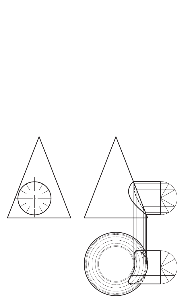
Figure 12.19
A cylinder meeting a hemisphere ( Fig. 12.19 ).
When you are a hard-working draughtsperson whose time is precious then BS 308
allows you to represent an intersection as a ‘ representative line ’ , usually a straight
Geometric and Engineering Drawing178
line. This assumes that a CAD program would be able to calculate the exact shape of
an intersection if required.
The solution is exactly the same as the last example except the sections are pro-
jected onto the EE and not the plan.
Fillet Curves
A sudden change of shape in any load-bearing component produces a stress centre, that
is, an area that is more highly stressed than the rest of the component and therefore more
liable to fracture under load. To avoid these sharp corners, fillet radii are used. These radii
allow the stress to be distributed more evenly, making the component stronger.
Sometimes , parts of these fillet radii are removed and a curve of intersection
results. Figure 12.20 shows an example of this.
Sections are taken on the FE. These appear on the plan as circles. The points
where these sections ‘ run off ’ the plan can easily be seen (at 1, 2, 3 and 4) and they
are projected up to the FE to meet their respective sections in 1 , 2 , 3 and 4 .
1
1′
2′
3′
4′
Fillet radius
First angle projection
Sect 1
Sect 1
Sect 2
Sect 3
Sect 4
Sect 2
Sect 3
Sect 4
234
Figure 12.20
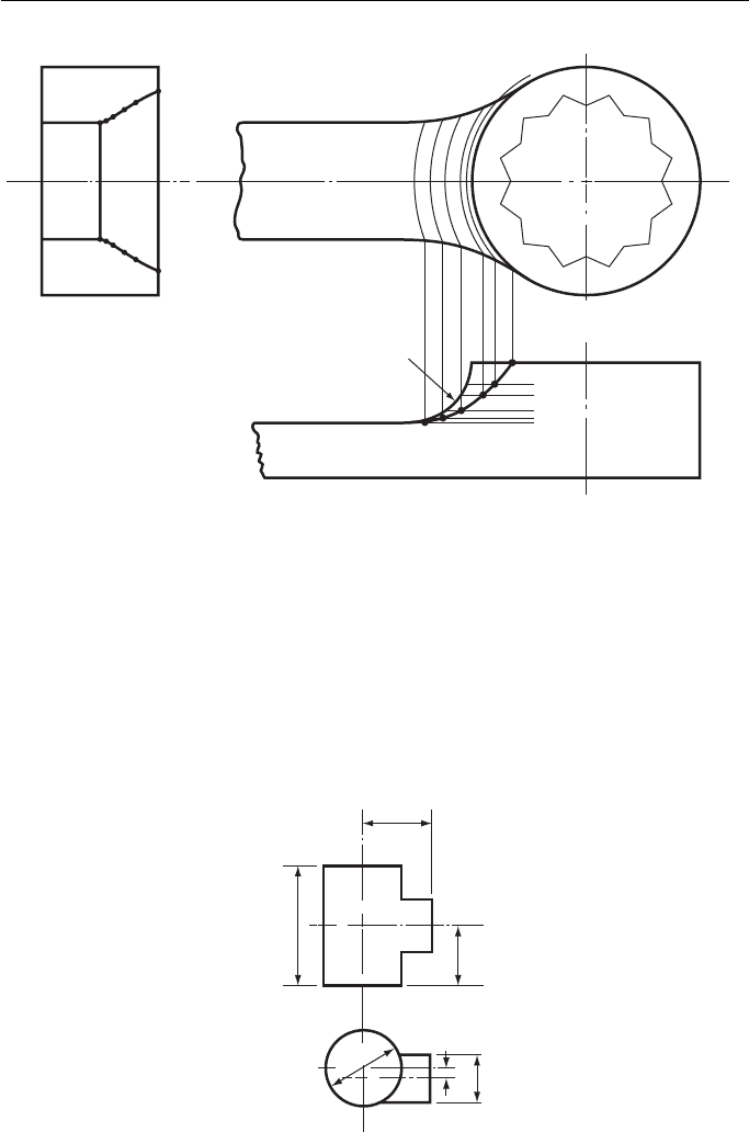
Figure 12.21 shows how a fillet radius could be used on the end of a ring
spanner.
Sections are taken on the FE and projected up to the plan (for the sake of clarity,
the projection lines for the sections are not shown). The points where these sections
‘ run off ’ the plan can easily be seen and these points (1, 2, 3, 4, etc.) are projected
down to the FE to meet their respective sections in 1 , 2 , 3 , 4 , etc.
BS 308 suggests that imaginary intersection lines can be shown in place of calcu-
lated intersection lines on working drawings.
Intersection of Regular Solids 179
Exercise 12
(All questions originally set in imperial units.)
1. Figure 1 shows the plan and incomplete elevation of two cylinders. Draw the two views,
showing any hidden lines.
North Western Secondary School Examinations Board
S
e
c
t
5
S
e
c
t
4
S
e
c
t
3
S
e
c
t
2
S
e
c
t
1
Sect 5
Sect 4
Sect 3
Sect 2
Sect 1
1'
1
2
3
4
5
2'
3'
3'
4'
5'
Fillet radius
Third angle projection
Figure 12.21
44
Dimensions in mm
76
38
φ 32
φ 50
6
Figure 1
Geometric and Engineering Drawing180
2. The plan and incomplete elevation of two pipes are shown in Fig. 2 . Copy the two views,
full size, and complete the elevation showing hidden detail.
Middlesex Regional Examining Board
φ 75 mm
φ 50 mm
75 mm
37mm
Figure 2
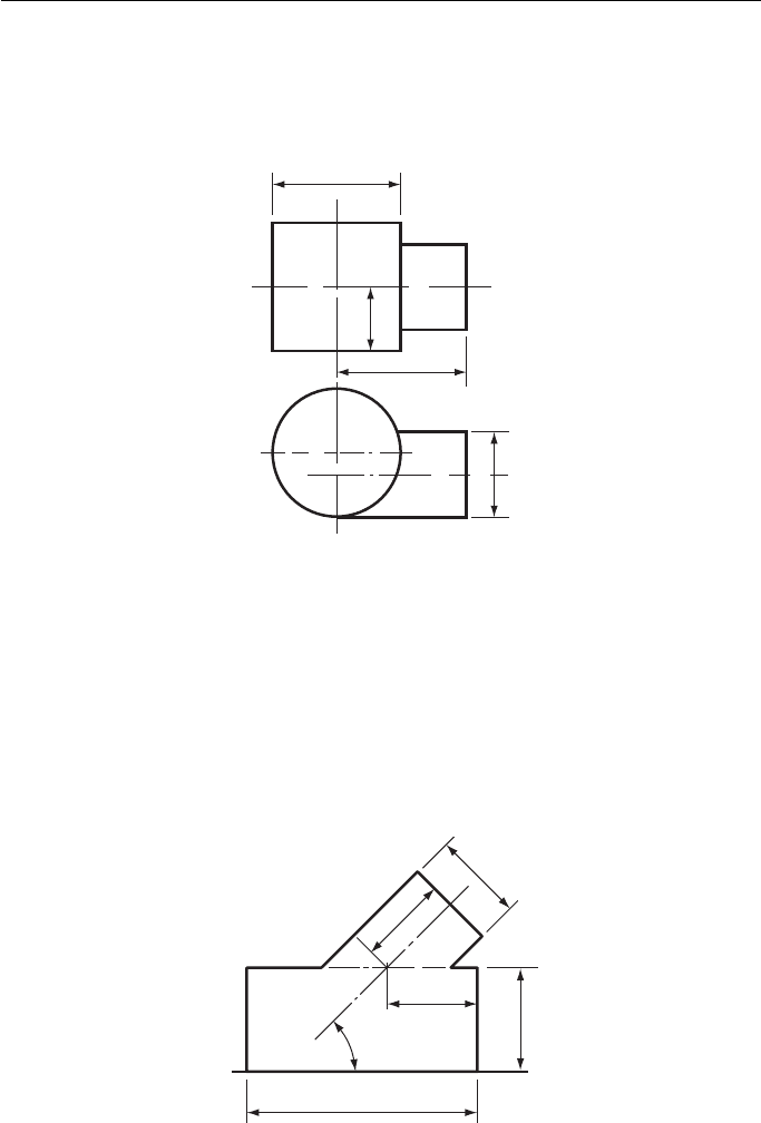
3. Figure 3 shows an incomplete elevation of the junction of a cylinder and an equilateral
triangular prism. The axes of both lie in the same VP. The prism rests with one of its side
faces in the HP.
Draw, and complete, the given elevation and project a plan. Do not show hidden detail.
Joint Matriculation Board
125 mm
XY
50 mm
50 mm
φ 56 mm
φ 50 mm
45°
Figure 3
Intersection of Regular Solids 181
4. Figure 4 shows incomplete drawings of the plan and elevation of a junction between a
square section pipe and a cylindrical pipe.
Draw (a) the complete plan and elevation and (b) the development of the whole surface of
either the square pipe or the cylindrical one.
Southern Universities ’ Joint Board (see Chapter 14 for information not in Chapter 12).
45°
150
50
50
Dimensions in mm
75
φ 50
Figure 4
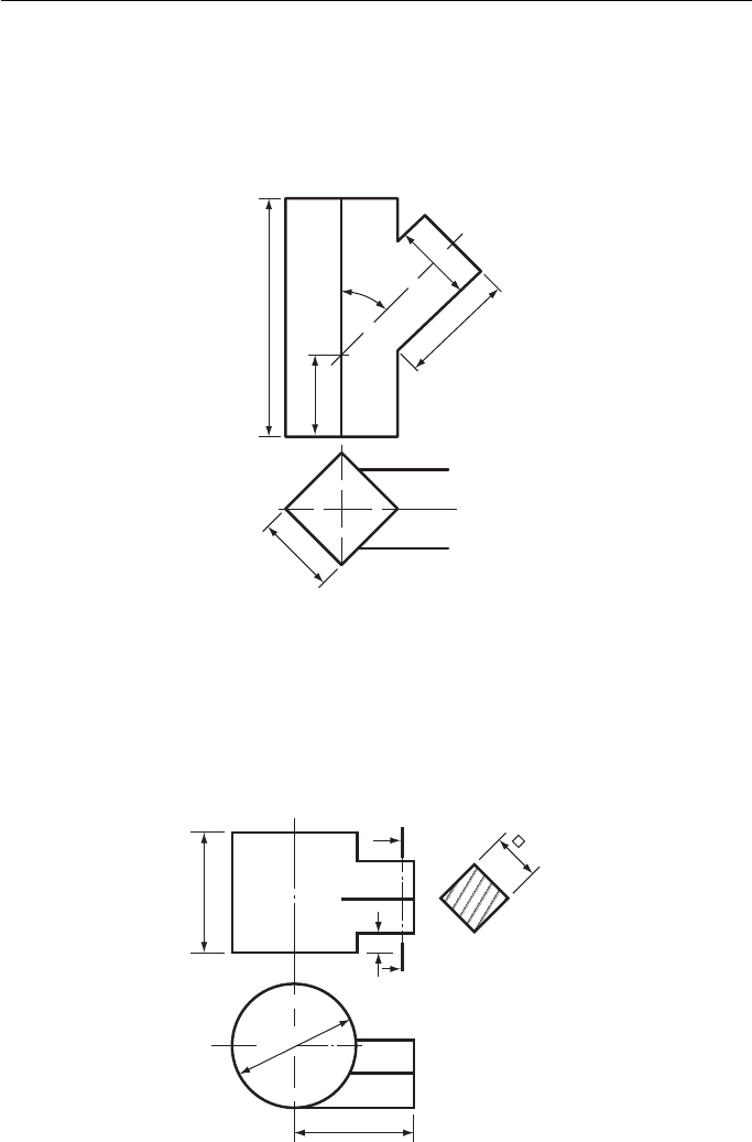
5. Figure 5 gives the plan and incomplete elevation of a junction between a cylinder and a
square prism. Copy the two views and complete the elevation showing all hidden detail.
Oxford and Cambridge Schools Examination Board
75
75
Dimensions in mm
φ 78
12
A
A
Section
on A–A
32
Figure 5
Geometric and Engineering Drawing182
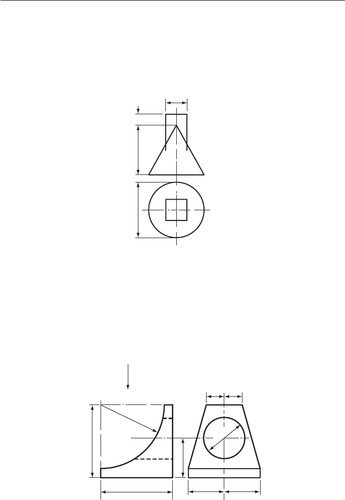
6. Figure 6 consists of a plan and incomplete elevation of a square prism intersecting a cone.
(a) Draw the given plan.
(b) Draw a complete elevation showing the curve of intersection.
(c) Develop the surface of the cone below the curve of intersection.
Southern Universities ’ Joint Board (see Chapter 14 for information not in Chapter 12).
30
Dimensions in mm
15
68φ 76
Figure 6
7. Two elevations of a wheel stop are shown in Fig. 7 . Draw, full size, (a) the given elevations,
(b) a plan looking in the direction of arrow Z .
Associated Examining Board
Z
R88
φ 56
100
100
Dimensions in mm
50
54
25 25
50
Figure 7
Intersection of Regular Solids 183
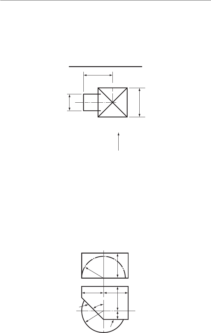
8. Figure 8 shows an incomplete plan view of the junction of a cylinder to a right square pyra-
mid. The axis of the cylinder is 32 mm above the base of the pyramid that stands on the HP.
Perpendicular height of the pyramid 100 mm.
Draw and complete the given plan and project an elevation looking in the direction of arrow A .
Draw, also, the development of the pyramid portion showing the hole required to receive
the cylinder. Show all hidden detail.
Joint Matriculation Board (see Chapter 14 for information not in Chapter 12).
66
X
Dimensions in mm
X
66
A
φ 38
Figure 8
9. The height of a right circular cone is 88 mm and the base diameter is 94 mm. The cone is
pierced by a square hole of side 32 mm. The axis of the hole intersects the axis of the cone
32 mm above the base and is parallel to the base.
Draw an elevation of the cone looking in a direction at right angles to the vertical faces of
the hole.
Oxford and Cambridge Schools Examination Board
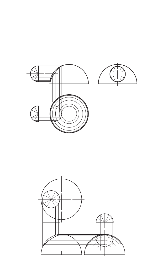
10. The plan and incomplete elevation of a solid are shown in Fig. 9 . Reproduce the given
views and complete the elevation by including the lines of intersection produced by the
vertical faces A and B. Hidden edges are to be shown.
Cambridge Local Examinations
56
56
56
21
45°
A
B
50
Dimensions in mm
R50
Hemi-
spherical
R50
Hemi-
spherical
Figure 9