Power electronic handbook
Подождите немного. Документ загружается.

338 F. L. Luo and H. Ye
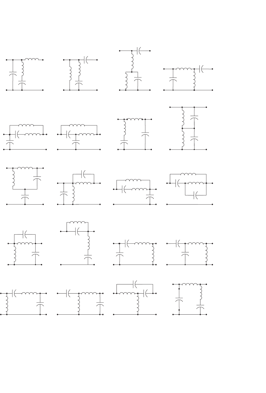
(21) (23) (24)(22)
(25) (26) (27) (28)
(29) (30)
(31)
(32)
(33) (34) (35) (36)
(37) (38) (40)(39)
FIGURE 14.110 continued.
14 DC/DC Conversion Technique and 12 Series Luo-converters 339
(41) (42)
(43)
(45) (46) (47)
(44)
(48)
(49) (51)(50) (52)
(53) (54) (55) (56)
(57) (58) (59) (60)
FIGURE 14.110 continued.
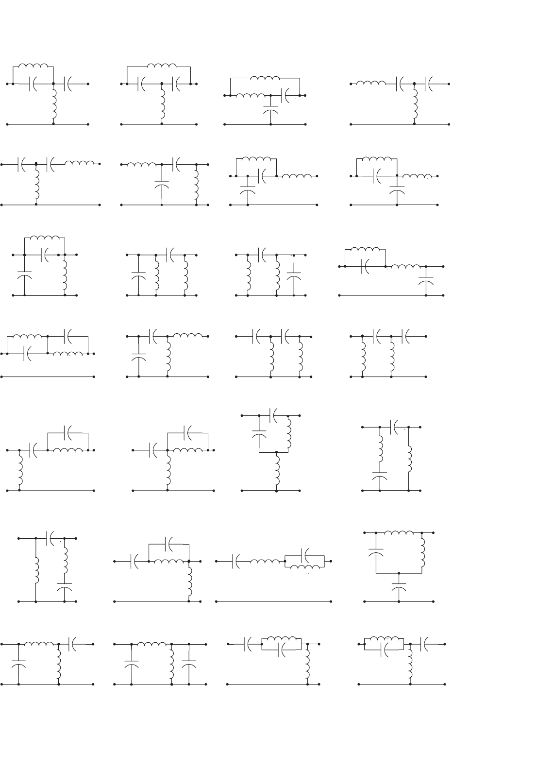
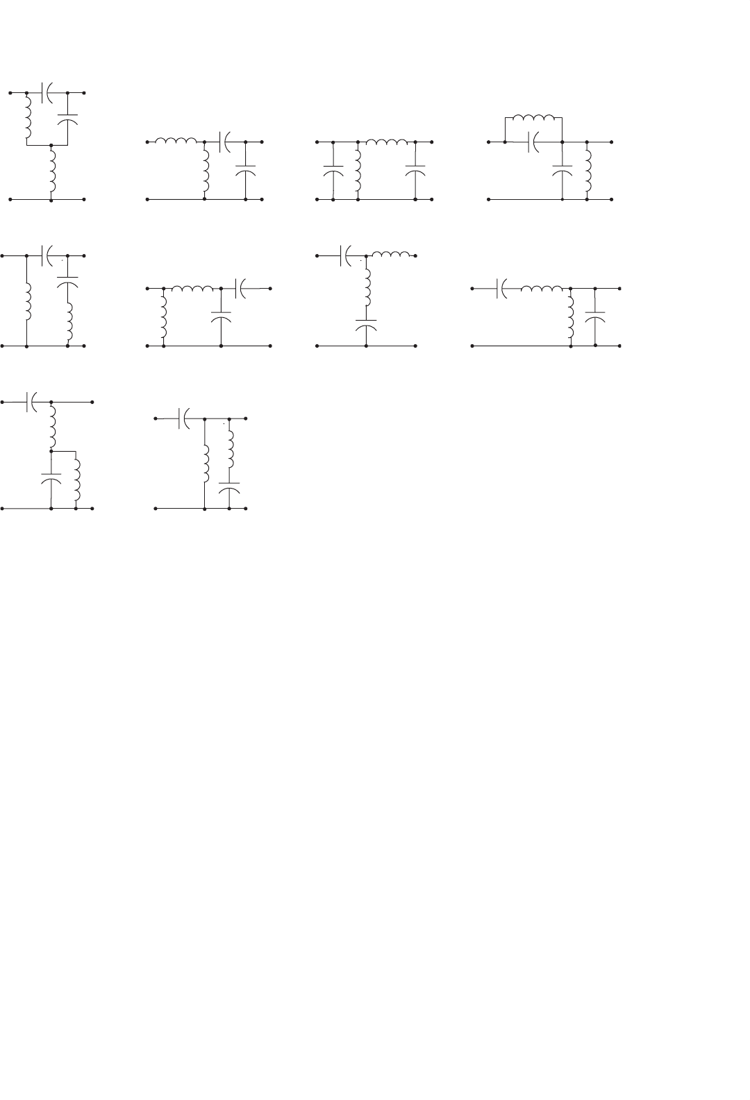
the number of the topologies of 4-element RPC can be much
larger. Although these topologies have comparably complex
circuit structure, they can still transfer the power from source
to end-users with higher power efficiency and lower power
losses.
Usually, the 4-element RPC has a wide response frequency
bands, which is defined as the frequency width between the
two half-power points. If the circuit is a low-pass filter, the
frequency bands can cover the frequency range from 0 to
the high half-power point which is definitely higher that
the natural resonant frequency ω
0
= 1/
√
LC. The working
point can be selected from a wide area across (lower and
higher than) the natural resonant frequency ω
0
= 1/
√
LC.
Another advantage is that the transferred waveform is usu-
ally a perfect sinusoidal, i.e. the output waveform THD is
very close to zero. As well-known, mono-frequency-waveform
340 F. L. Luo and H. Ye
(61) (62) (63) (64)
(65) (66) (67) (68)
(69) (70) (71) (72)
(73) (75) (76)(74)
(77) (78) (79) (80)
( 81 ) ( 82 ) ( 84 )
( 85 )
( 83 )
( 87 ) ( 88)
( 86 )
FIGURE 14.110 continued.
14 DC/DC Conversion Technique and 12 Series Luo-converters 341
( 89) ( 90 )
( 91 ) ( 92)
( 94 )( 93 ) ( 95 ) ( 96)
( 97 ) ( 98 )
FIGURE 14.110 continued.
transferring operation has very low EMI and reasonable EMS
and EMC.
14.14.4 Bipolar Current and Voltage Sources
Depending on different applications, resonant network can be
low-pass filter, high-pass filter, or band-pass filter. For large
power transferring, low-pass filter is usually employed. In this
case, inductors are arranged in series arms and capacitors are
arranged in shunt arms. If the first component is inductor,
only voltage source can be applied since inductor current is
continuous. Vice versa, if the first component is capacitor,
only current source can be applied since capacitor voltage is
continuous.
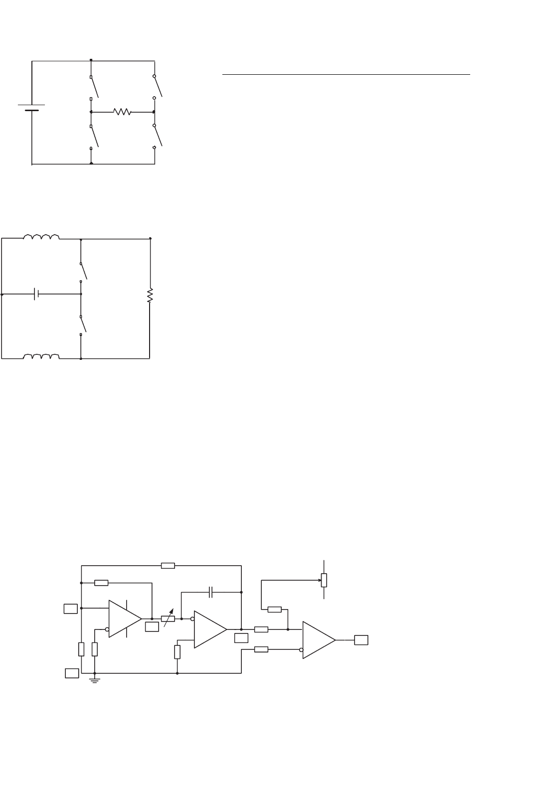
14.14.4.1 Bipolar Voltage Source
A bipolar voltage source using single voltage source is shown in
Fig. 14.111. Since only voltage source is applied, there are four
switches applied alternatively switching on or off to supply
positive and negative voltage to the network. In the figure, the
load is a resistance R.
The circuit of this voltage source is likely a four-quadrant
operational chopper. The conduction duty cycle for each
switch is 50%. For safety reason, the particular circuitry
design has to consider some small gap between the turn-
over (commutation) operation to avoid the short-circuit
incidence.
The repeating frequency is theoretically not restricted. For
industrial applications, the operating frequency is usually
arranged in the range between 10 kHz and 5 MHz, depending
on the application conditions.
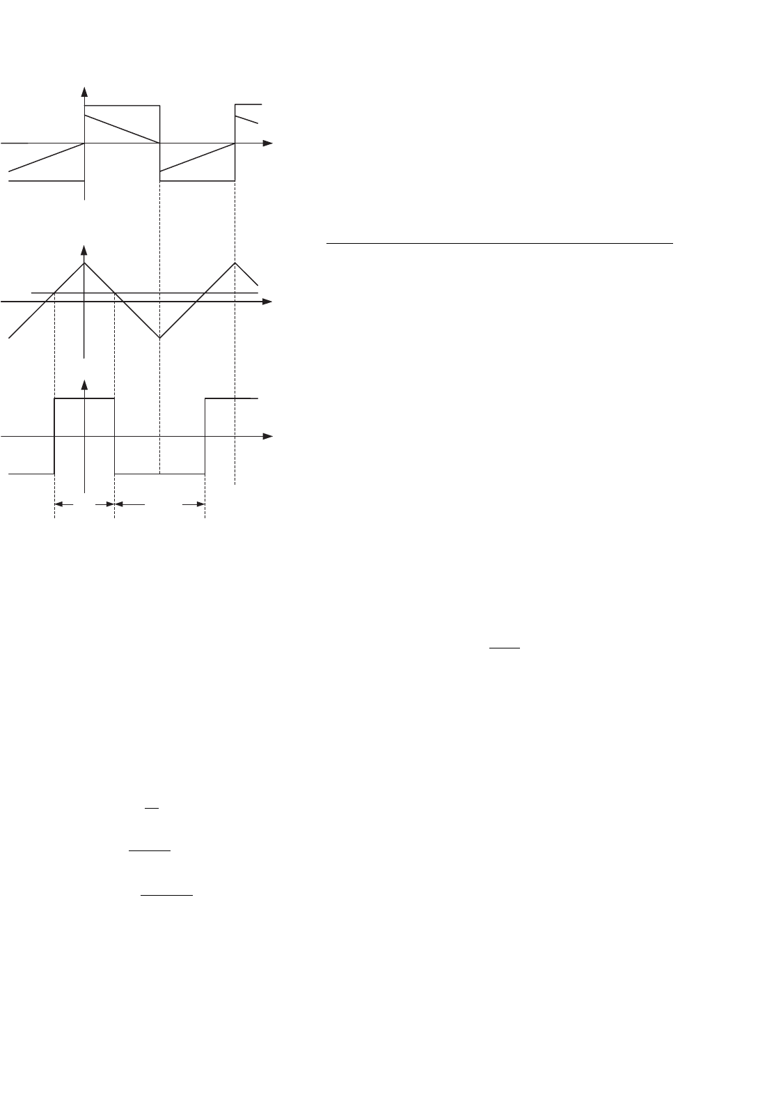
14.14.4.2 Bipolar Current Source
A bipolar current voltage source using single voltage sources
is shown in Fig. 14.112. To obtain stable current, the voltage
source is connected in series by a large inductor. There are four
switches applied alternatively switching on or off to supply
positive and negative current to the network. In the figure, the
load is a resistance R.
The circuit of this current source is likely a two-quadrant
operational chopper. The conduction duty cycle for each
342 F. L. Luo and H. Ye
+V
S
1
S
2
R
V
O
S
3
S
4
FIGURE 14.111 A bipolar voltage source using single voltage source.
+V
L
1
L
2
S
1
S
2
R
V
O
FIGURE 14.112 A bipolar current voltage source using single voltage
source.
switch is 50%. For safety reason, the particular circuitry
design has to consider some small gap between the turn-
over (commutation) operation to avoid the short-circuit
incidence.
The repeating frequency is theoretically not restricted. For
industrial applications, the operating frequency is usually
arranged in the range between 10 kHz and 5 MHz, depending
on the application conditions.
OA1
OA2
OA3
A
R
1
G
R
O
R
O
R
O
C
C
R
2
R
3
R
7
R
6
R
5
R
4
(f)
B
V−
V+
D
V+
V−
V
off-set
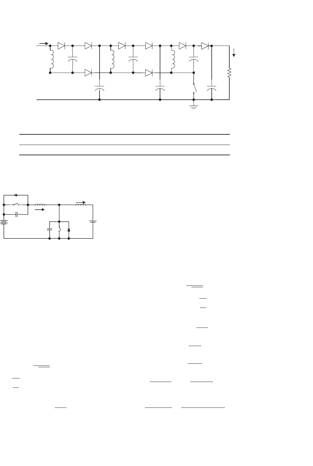
FIGURE 14.113 Luo-resonator.
14.15 Gate Control Luo-resonator
Luo-resonator is shown in Fig. 14.113. It generates the PWM
pulse train to drive the static switch S. Luo-resonator is a high
efficiency and simple structure circuit with easily adjusting
frequency f and conduction duty k. It consists of three oper-
ational amplifiers (OA) named OA1-3 and auxiliary. These
three 741-type OA’s are integrated in a chip TL074 (which
contains four OA’s). Two potentiometers are applied to adjust
the frequency f and conduction duty k. The voltage waveforms
are shown in Fig. 14.114.
Type-741 OA can work at the power supply ±3 −±18 V
that are marked V +, G, and V − with |V −|=V +. OA2 in
Fig. 14.113 acts as the integration operation, its output V
C
is
a triangle waveform with regulated frequency f = 1/T con-
trolled by potentiometer R
4
. OA1 acts as a resonant operation,
its output V
B
is a square-waveform with the frequency f. OA3
acts as a comparator, its output V
D
is a square-waveform pulse
train with regulated conduction duty k controlled by R
7
.
Firstly, assuming the voltage V
B
= V + at t = 0 and feeds
positively back to OA1 via R
2
. This causes the OA1’s out-
put voltage maintained at V
B
= V +. In the meantime, V
B
inputs to OA2 via R
4
, the output voltage V
C
of OA2, therefore,
decreases towards V − with the slope 1/R
4
C. Voltage V
C
feeds
negatively back to OA1 via R
3
. Voltage V
A
at point A changes
from (mV +) to 0 in the period of 2mR
4
C. Usually, R
3
is
set slightly smaller than R
2
, the ratio is defined as m = R
3
/R
2
.
Thus, voltage V
A
intends towards negative. It causes the OA1’s
output voltage V
B
= V −at t = 2mR
4
C and voltage V
A
jumps
to mV −. Vice versa, the voltage V
B
= V − at t = 2mR
4
C and
feeds positively back to OA1 via R
2
. This causes the OA1’s
output voltage maintained at V
B
= V −. In the meantime,
V
B
inputs to OA2 via R
4
, the output voltage V
C
of OA2, there-
fore, increases towards V + with the slope 1/R
4
C. Voltage V
C
feeds negatively back to OA1 via R
3
. Voltage V
A
at point A
changes from (mV −) to 0 in the period of 2mR
4
C. Thus,
voltage V
A
intends towards positive. It causes the OA1’s out-
put voltage V
B
= V + at t = 4mR
4
C and voltage V
A
jumps
to mV +.
14 DC/DC Conversion Technique and 12 Series Luo-converters 343
V
A
, V
B
t
0
V+
V−
T
mV+
V
B
V
A
mV−
V
C
0
V+
V−
V
C
V
off-set
0
V+
V−
V
D
t
T
t
T
kT(1−k)T
FIGURE 14.114 Voltage waveforms of Luo-resonator.
Then V
C
inputs to OA3 and compares with shift sig-
nal V
off -set
regulated by the potentiometer R
7
via R
6
. When
V
off -set
= 0, OA3 yields its output voltage V
D
as a pulse
train with conduction duty k = 0.5. Positive V
off -set
shifts
the zero-cross point of voltage V
C
downwards, hence, OA3
yields its output voltage V
D
as a pulse train with conduction
duty k > 0.5. Vice versa, negative V
off -set
shifts the zero-cross
point of voltage V
C
upwards, hence, OA3 yields its output
voltage V
D
as a pulse train with conduction duty k < 0.5
as shown in Fig. 14.114. Conduction duty k is controlled by
V
off -set
via the potentiometer R
7
.
The calculation formulas are
m =
R
3
R
2
(14.389)
f =
1
4mR
4
C
(14.390)
k = 0.5 +
R
5
V
off -set
2R
6
V +
(14.391)
This PWM pulse train V
D
is applied to the DC/DC converter
switch such as a transistor, MOSFET, or IGBT via a coupling
circuit.
A design example: A Luo-resonator was designed as shown
in Fig. 14.113 with the component values of R
0
= 10 k;
R
1
= R
2
= R
5
= 100 k, R
3
= R
6
= 95 k; R
4
= 510 –
5.1 k R
7
= 20 k; and C = 5.1 nF. The results are
m = 0.95, frequency f = 10–100 kHz and conduction duty
k =0–1.0.
14.16 Applications
The DC/DC conversion technique has been rapidly developed
and has been widely applied in industrial applications and
computer peripheral equipment. Three examples are listed
below:
• 5000 V insulation test bench;
• MIT 42/14 V DC/DC converter;
• IBM 1.8 V/200 A power supply.
14.16.1 5000 V Insulation Test Bench
Insulation test bench is the necessary equipment for semi-
conductor manufacturing organizations. An adjustable DC
voltage power supply is the heart of this equipment. Tradi-
tional method to obtain the adjustable high DC voltage is a
diode rectifier via a setting up transformer. It is costly and
larger in size with poor efficiency.
Using a positive output super-lift Luo-converter triple-
lift circuit, which is shown in Fig. 14.115. This circuit is
small, effective, and low cost. The output voltage can be
determined by
V
O
=
2 −k
1 −k
3
V
in
(14.392)
The conduction duty cycle k is only adjusted in the
range 0–0.8 to carry out the output voltage in the range of
192–5184 V.
The experimental results are listed in Table 14.14. The
measured data verified the advantages of this power supply.
14.16.2 MIT 42/14 V–3 KW DC/DC Converter
MIT 42/14 V–3 KW DC/DC converter was requested to trans-
fer 3 kW energy between two battery sources with 42 and 14 V.
The circuit diagram is shown in Fig. 14.116. This is a
two-quadrant zero-voltage-switching (ZVS) quasi-resonant-
converter (QRC). The current in low voltage side can be up to
250 A. This is a typical low voltage strong current converter.
It is easier to carry out by ZVS-QRC.
This converter consists of two sources V
1
and V
2
, one main
inductor L, two main switches S
1
and S
2
, two reverse-paralleled
344 F. L. Luo and H. Ye
L
1
R
D
1
C
1
D
2
C
2
I
in
V
in
+
−
V
C1
+
−
V
C2
+
−
V
O
+
−
I
O
D
3
L
2
D
4
C
3
D
5
V
C3
+
−
C
4
V
C4
+
−
V
1
S
D
6
L
3
D
7
C
5
V
2
C
6
V
C6
+
−
D
8
V
C5
+
−
V
I
= +24V
FIGURE 14.115 5000 V Insulation test bench.
TABLE 14.14 The experimental results of the 5000 V test bench
Conduction duty, k 0 0.1 0.2 0.3 0.4 0.5 0.6 0.7 0.8 0.82
Output voltage V
O
(V) 192 226 273 244 455 648 1029 1953 5184 6760
V
1
V
2
S
1
S
2
D
1
D
2
L
r
C
r2
L
i
L
i
r
C
r1
+
−
+
−
FIGURE 14.116 MIT 42/14 V-3 kW DC/DC converter.
diodes D
1
and D
2
, one resonant inductor L
r
and two resonant
capacitors C
r1
and C
r2
. The working condition is selected
V
1
= 42 V; V
2
= 14 V
L = 470 µH; C
r1
= C
r2
= C
r
= 1 µF
L
r
=
1 µH normal operation
9 µH low current operation
Therefore,
ω
O
=
1
√
L
r
C
r
= 10
6
rad/s (14.393)
Z
O
=
L
r
C
r
= 1 (normal operation) (14.394)
α = sin
−1
V
1
Z
O
I
2
(14.395)
It is easy to keep the quasi-resonance when the working cur-
rent I
2
> 50 A. If the working current is too low, the resonant
inductor will take large value to guarantee the quasi-resonance
state. This converter performs two-quadrant operation:
• Mode A (Quadrant I): energy transferred from V
1
side to
V
2
side;
• Mode B (Quadrant II): energy transferred from V
2
side
to V
1
side.
Assuming the working current is I
2
= 100 A and the con-
verter works in Mode A, following calculations are obtained
ω
O
=
1
√
L
r
C
r
= 10
6
rad/s
Z
O
=
L
r
C
r
= 1
α = sin
−1
V
1
Z
O
I
2
= 24.83
◦
(14.396)
t
1
=
V
1
C
r
I
2
= 0.42 µs (14.397)
t
2
=
π +α
ω
O
= 3.58 µs (14.398)
t
3
=
1 +cos α
V
1
I
2
L
r
=
1 +0.908
42
100 ×10
−6
= 4.54 µs
(14.399)
t
4
=
t
1
+t
2
+t
3
V
1
/V
2
−1
=
0.42 +3.58 +4.54
2
= 4.27 µs (14.400)

14 DC/DC Conversion Technique and 12 Series Luo-converters 345
TABLE 14.15 The experimental test results of MIT 42V/14 converter
(with the condition: L
r
= 1 µH, C
r1
= C
r2
= 1 µF)
Mode f (kHz) I
1
(A) I
2
(A) I
L
(A) P
1
(W) P
2
(W) η (%) PD (W/in
3
)
A 78 77.1 220 220 3239 3080 95.1 23.40
A 80 78.3 220 220 3287 3080 93.7 23.58
A 82 81 220 220 3403 3080 90.5 24.01
B 68 220 69.9 220 3080 2939 95.3 22.28
B 70 220 68.3 220 3080 2871 93.2 22.04
B 72 220 66.6 220 3080 2797 90.8 21.77
T = t
1
+t
2
+t
3
+t
4
= 0.42 +3.58 +4.54 +4.27 = 12.81 µs
(14.401)
f =
1
T
=
1
12.81
= 78.06 kHz (14.402)
k =
t
3
+t
4
T
=
4.54 +4.27
12.81
= 0.688 (14.403)
The volume of this converter is 270 in
3
. The experimen-
tal test results in full power 3 kW are listed in Table 14.15.
From the tested data, a high power density 22.85 W/in
3
and
a high efficiency 93% are obtained. Because of soft-switching
operation, the EMI is low and EMS and EMC are reasonable.
14.16.3 IBM 1.8 V/200 A Power Supply
This equipment is suitable for IBM new generation computer
with power supply 1.8 V/200 A. This is a ZCS SR DC/DC
Luo-converter, and is shown in Fig. 14.117. This converter
is based on the double-current synchronous-rectifier DC/DC
converter plus ZCS technique. It employs a hixaploid-core flat-
transformer with the turns ratio N = 1/12. It has six-unit ZCS
synchronous-rectifier double-current DC/DC converter. The
six primary coils are connected in series, and six secondary cir-
cuits are connected in parallel. Each unit has particular input
voltage V
in
to be about 33 V, and can offer 1.8 V/35 A individ-
ually. Total output current is 210 A. The equivalent primary
full current is I
1
= 14.5 A and equivalent primary load voltage
is V
2
= 200 V. The ZCS natural resonant frequency is
ω
O
=
1
√
L
r
C
r
(14.404)
Z
O
=
L
r
C
r
(14.405)
α = sin
−1
Z
O
I
1
V
1
(14.406)
The main power supply is from public utility board (PUB)
via a diode rectifier. Therefore V
1
is nearly 200 V, and the
each unit input voltage V
in
is about 33 V. Other calculation
formulas are
t
1
=
I
1
L
r
V
1
(14.407)
t
2
=
π +α
ω
O
(14.408)
t
3
=
1 +cos α
I
1
V
1
C
r
(14.409)
t
4
=
V
1
(t
1
+t
2
)
I
1
V
2
I
1
+
V
Z
O
cos α
π/2 +α
−(t
1
+t
2
+t
3
)
(14.410)
T = t
1
+t
2
+t
3
+t
4
(14.411)
f =
1
T
(14.412)
k =
t
1
+t
2
T
(14.413)
Real output voltage and input current are
V
O
= kNV
1
−
R
L
+R
S
+
L
m
T
N
2
I
O
(14.414)
I
in
= kNI
O
(14.415)
The efficiency is
η =
V
O
I
O
V
in
I
in
= 1 −
R
L
+R
S
+(L
m
/T)N
2
kNV
in
I
O
(14.416)
The commercial unit of this power supply works in voltage
closed loop control with inner current closed loop to keep the
output voltage constant. Applying frequency is arranged in
the band of 200–250 kHz. Whole volume of the power supply
is 14 in
3
. The transfer efficiency is about 88–92% and power
density is about 25.7 W/in
3
.
14.17 Energy Factor and Mathematical
Modeling for Power
DC/DC Converters
We have well discussed the various DC/DC converters oper-
ating in steady state in previous sections. We will investigate
the transient process of DC/DC converters. Furthermore, we
define a series of new parameters such as energy factor (EF)
and so on to establish the mathematical modeling of all power
DC/DC converters.
Energy storage in power DC/DC converters has been paid
attention long time ago. Unfortunately, there is no clear
346 F. L. Luo and H. Ye
C
L
m
S
2
R
L
2
D
3
D
4
S
4
S
3
C
O
V
2
+
−
FT
N:1
L
1
S
1
PWM
i
2
V
1
+
−
C
r
D
2
D
1
L
r
Unit 2
Unit 1
Unit 3
Unit 4
Unit 5
Unit 6
FIGURE 14.117 IBM 1.8 V/200 A power supply.
concept to describe the phenomena and reveal the relation-
ship between the stored energy and the characteristics of power
DC/DC converters. We have theoretically defined a new con-
cept – energy factor (EF) and researched the relations between
EF and the mathematical modeling of power DC/DC con-
verters. Energy factor is a new concept in power electronics
and conversion technology, which thoroughly differs from the
traditional concepts such as power factor (PF), power trans-
fer efficiency (η), total harmonic distortion (THD), and ripple
factor (RF). Energy factor and the other sub-sequential param-
eters can illustrate the system stability, reference response,
and interference recovery. This investigation is very help-
ful for system design and DC/DC converters characteristics
foreseeing.
14.17.1 Pumping Energy (PE)
All power DC/DC converters have pumping circuit to transfer
the energy from the source to some energy storage passive
elements, e.g. inductors and capacitors. The PE is used to
count the input energy in a switching period T. Its calculation
formula is
PE =
T
0
P
in
(t)dt =
T
0
V
1
i
1
(t)dt = V
1
I
1
T (14.417)
where
I
1
=
T
0
i
1
(t)dt
is the average value of the input current if the input voltage
V
1
is constant. Usually the input average current I
1
depends
on the conduction duty cycle.
14.17.2 Stored Energy (SE)
The stored energy in an inductor is
W
L
=
1
2
LI
2
L
(14.418)
The stored energy across a capacitor is
W
C
=
1
2
CV
2
C
(14.419)
Therefore, if there are n
L
inductors and n
C
capacitors the
total stored energy in a DC/DC converter is
SE =
n
L
j=1
W
Lj
+
n
C
j=1
W
Cj
(14.420)
Capacitor–inductor stored energy ratio (CIR)–Most
power DC/DC converters consist of inductors and capacitors.

14 DC/DC Conversion Technique and 12 Series Luo-converters 347
Therefore, we can define the capacitor–inductor stored energy
ratio (CIR).
CIR =
n
C
j=1
W
Cj
n
L
j=1
W
Lj
(14.421)
Energy losses (EL)–Usually, most analysis applied in
DC/DC converters is assuming no power losses, i.e. the input
power is equal to the output power, P
in
= P
O
or V
1
I
1
=
V
2
I
2
, so that pumping energy is equal to output energy in a
period, T.
Particularly, power losses always exist during the conversion
process. They are caused by the resistance of the connec-
tion cables, resistance of the inductor and capacitor wire, and
power losses across the semiconductor devices (diode, IGBT,
MOSFET, and so on). We can sort them as the resistance
power losses P
r
, passive element power losses P
e
, and device
power losses P
d
. The total power losses are P
loss
.
P
loss
= P
r
+P
e
+P
d
and
P
in
=P
O
+P
loss
=P
O
+P
e
+P
e
+P
d
=V
2
I
2
+P
e
+P
e
+P
d
Therefore,
EL = P
loss
×T = (P
r
+P
e
+P
d
)T
The energy losses (EL) is in a period T,
EL =
T
0
P
loss
dt = P
loss
T (14.422)
14.17.3 Energy Factor (EF)
As described in previous section the input energy in a period T
is the pumping energy PE = P
in
× T = V
in
I
in
× T . We now
define the EF, that is the ratio of the SE over the pumping
energy
EF =
SE
PE
=
SE
V
1
I
1
T
=
m
j=1
W
Lj
+
n
j=1
W
Cj
V
1
I
1
T
(14.423)
Energy factor is a very important factor of a power DC/DC
converter. It is usually independent from the conduction
duty cycle k, and proportional to the switching frequency f
(inversely proportional to the period T) since the pumping
energy PE is proportional to the switching period T.
14.17.4 Time Constant τ and Damping Time
Constant τ
d
The time constant τ of a power DC/DC converter is a
new concept to describe the transient process of a DC/DC
converter. If no power losses in the converter, it is defined
τ =
2T × EF
1 +CIR
1 +CIR
1 −η
η
(14.424)
The damping time constant τ
d
of a power DC/DC con-
verter is new concept to describe the transient process of a
DC/DC converter. If no power losses, it is defined
τ
d
=
2T × EF
1 +CIR
CIR
η +CIR(1 − η)
(14.425)
The time constants ratio ξ of a power DC/DC converter
is new concept to describe the transient process of a DC/DC
converter. If no power losses, it is defined
ξ =
τ
d
τ
=
CIR
η
1 +CIR
1−η
η
2
(14.426)
14.17.5 Mathematical Modeling for Power
DC/DC Converters
The mathematical modeling for all power DC/DC converters is
G(s) =
M
1 +sτ + s
2
ττ
d
(14.427)
where M is the voltage transfer gain: M = V
O
/V
in
, τ is the
time constant in Eq. (14.424), τ
d
the damping time constant
in Eq. (14.425), τ
d
= ξτ. Using this mathematical model of
power DC/DC converters, it is significantly easy to describe the
characteristics of power DC/DC converters. In order to verify
this theory, few converters are investigated to demonstrate the
characteristics of power DC/DC converters and applications
of the theory.
14.17.6 Buck Converter with Small Energy
Losses (r
L
= 1.5 )
A buck converter shown in Fig. 14.118 has the components
values: V
1
= 40 V, L = 250 µH with resistance r
L
= 1.5 ,
C = 60 µF, R = 10 , the switching frequency f = 20 kHz
(T = 1/f = 50 µs) and conduction duty cycle k = 0.4. This
converter is stable and works in CCM.
Therefore, we have got the voltage transfer gain M = 0.35,
i.e. V
2
= V
C
= MV
1
= 0.35 × 40 = 14 V. I
L
= I
2
= 1.4 A,
P
loss
= I
2
L
×r
L
= 1.4
2
×1.5 = 2.94 W, and I
1
= 0.564 A. The
parameter EF and others are listed below
PE = V
1
I
1
T = 40 × 0.564 × 50 µ = 1.128 mJ;