Power electronic handbook
Подождите немного. Документ загружается.

784 V. K. Sood
Pole
differential
Protection
differential
Protection
DCPT
DCCT
V
d
I
d
I
d
I’
ac
I
ac
V
ac
PT
Circuit
Breaker
Valve Group
Protection
Over Current
Protection
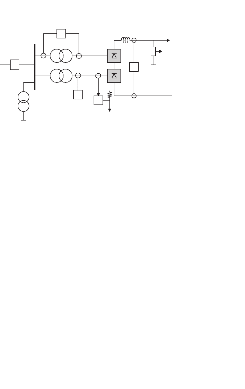
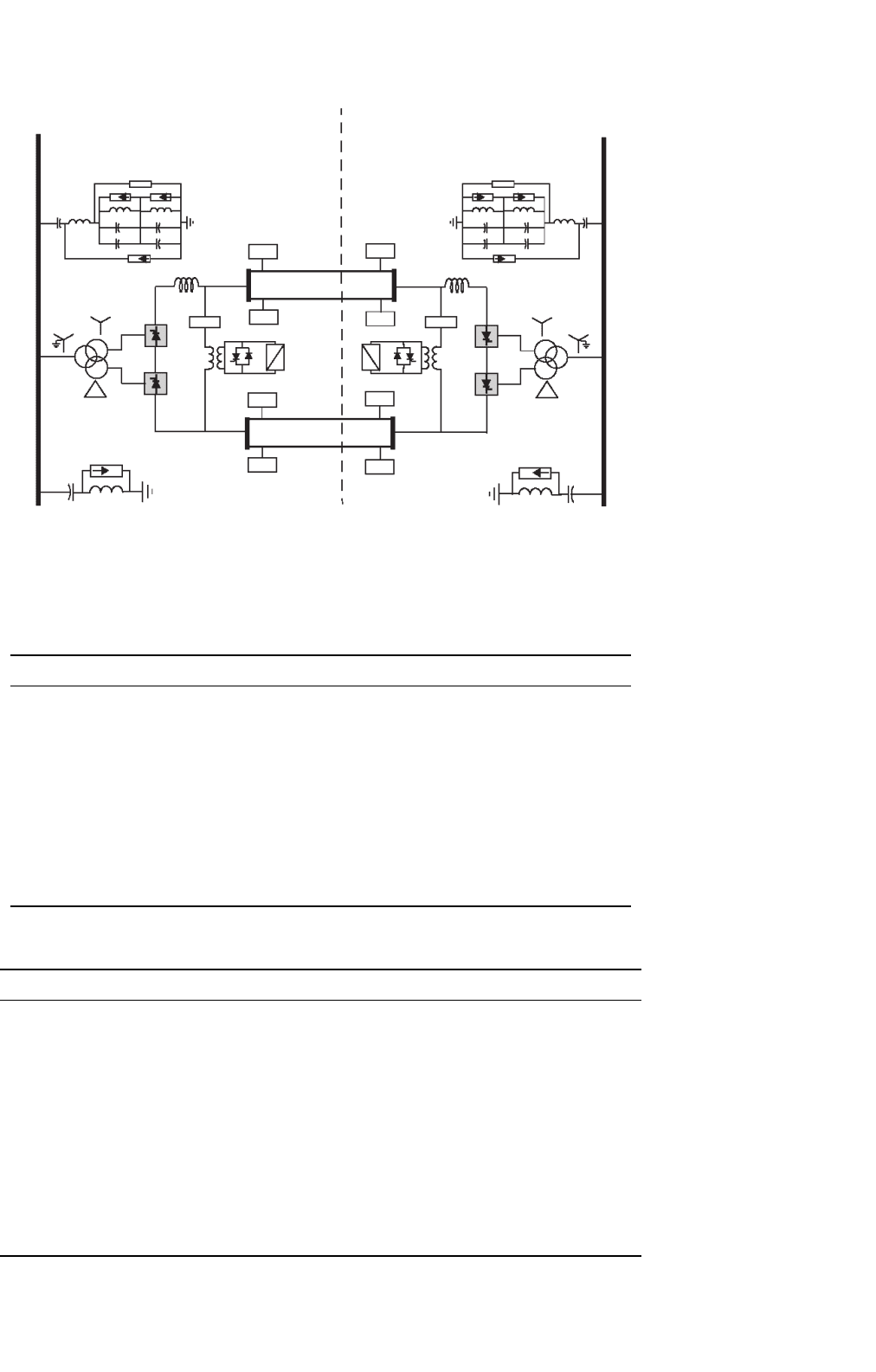
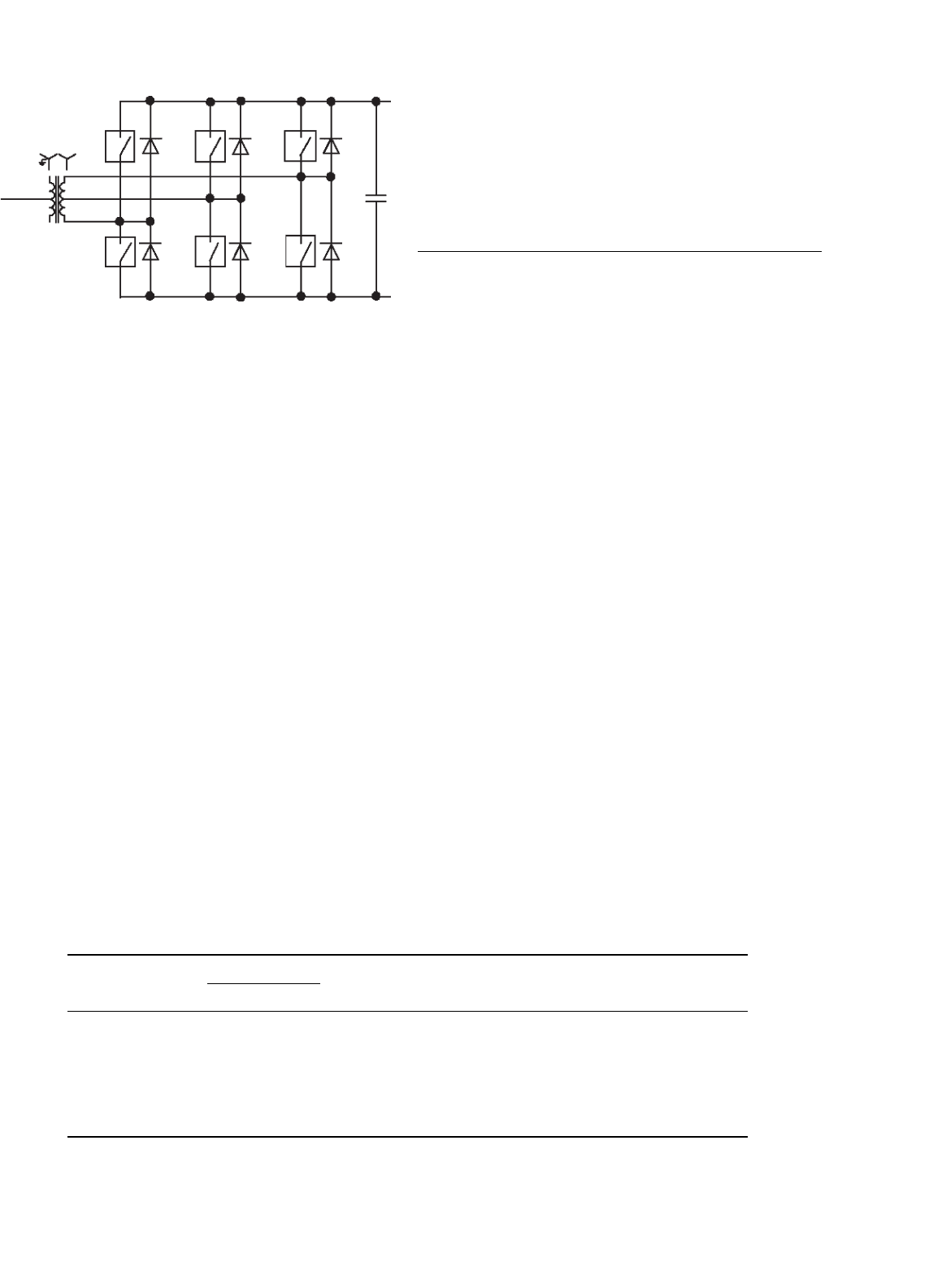
FIGURE 30.17 Monitoring points for the protection circuits.
the converter transformer. These measurements assist
in the rapid alteration of firing angle for protection of
the valves during perturbations. A slow loop for con-
trol of tap changer position as a function of alpha is
also available at this level.
30.4.5 Monitoring of Signals
As described earlier, monitoring of the following signals is nec-
essary for the controls (Fig. 30.17) to perform their functions
and assist in the protection of the converter equipment:
V
d
, I
d
– dc voltage and dc current respectively.
I
ac
, I ’
ac
– ac current on line side and converter side of the
converter transformer respectively.
V
ac
– ac voltage at the ac filter bus.
30.4.6 Protection against Overcurrents
Faults and disturbances can be caused by malfunctioning
equipment or insulation failures due to lightening and pol-
lution. First, these faults need to be detected with the help of
monitored signals. Second, the equipment must be protected
by control or switching actions. Since dc controls can react
within one cycle, control action is used to protect equipment
against overcurrent and overvoltage stresses, and minimize
loss of transmission. In a converter station, the valves are the
most critical (and most expensive) equipment that needs to be
protected rapidly due to their limited thermal inertia.
The basic types of faults that the converter station can
experience are:
Current extinction (CE)
Current extinction can occur if the valve current drops below
the holding current of the thyristor. This can happen at
low-current operation accompanied by a transient leading to
current extinction. Due to the phenomena of current chop-
ping of an inductive current, severe overvoltages may result.
The size of the smoothing reactor and the rectifier mini-
mum current setting I
min
helps to minimize the occurrence
of CE.
Commutation failure (CF) or misfire
In line-commutated converters, the successful commutation of
a valve requires that the extinction angle γ-nominal be main-
tained more than the minimum value of the extinction angle
γ-min. Note that γ-nominal = 180−α−µ. The overlap angle,
µ is a function of the commutation voltage and the dc current.
Hence, a decrease in commutation voltage or an increase in
dc current can cause an increase in µ, resulting in a decrease
in γ-nominal. If γ-nominal <γ-min, a CF may result. In this
case, the outgoing valve will continue to conduct current and
when the incoming valve is fired in sequence, a short circuit
of the bridge will occur.
A missing firing pulse can also lead to a misfire (at a rectifier)
or a CF (at an inverter). The effects of a single misfire are sim-
ilar to those of a single CF. Usually a single CF is self-clearing,
and no special control actions are necessary. However, a mul-
tiple CF can lead to the injection of ac voltages into the dc
system. Control action may be necessary in this case.
The detection of a CF is based on the differential comparison
of dc current and the ac currents on the valve side of the
converter transformer. During a CF, the two valves in an arm
of the bridge are conducting. Therefore, the ac current goes to
zero while the dc current continues to flow.
The protection features employed to counteract the impact
of a CF are indicated in Table 30.4.
Short circuits – internal or dc line
An internal bridge fault is rare as the valve hall is completely
enclosed and is air-conditioned. However, a bushing can fail,
30 HVDC Transmission 785
TABLE 30.4 Protection against overcurrents
Fault type Occurrence Fault current
level
Protection method
Internal faults Infrequent 10 pu Valve is rated to withstand this surge
DC line faults Frequent 2–3 pu – Forced retard of firing angle
– Dynamic VDCL deployment
– Trip ac breaker CB after third attempt
Commutation failures
(single or multiple)
Very frequent 1.5–2.5 pu Single CF:
– Self-clearing
Multiple CF:
–Beta angle advanced in stages
– Static VDCL deployment
or valve-cooling water may leak resulting in a short circuit.
The ac breaker may have to be tripped to protect against bridge
faults.
The protection features employed to counteract the impact
of short circuits are indicated in Table 30.4.
The fast-acting HVDC controls (which operate within one
cycle) are used to regulate the dc current for protection of the
valves against ac and dc faults.
The basic protection (Fig. 30.18) is provided by the VGP
differential protection that compares the rectified current on
the valve side of the converter transformer with the dc cur-
rent measured on the line side of the smoothing reactor.
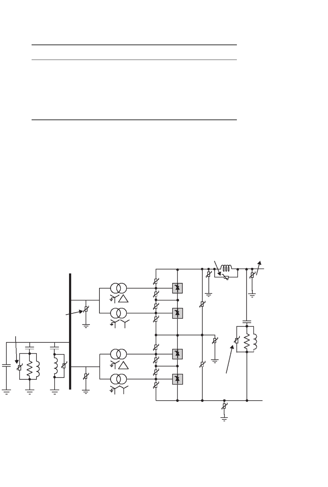
This method is applied because of its selectivity possible due
Neutral arrestor
DC filter arrestor
Mid-point DC
bus arrestor
Converter arrestor
DC reactor arrestor
Valve arrestor
AC reactor arrestor
AC filter arrestor
AC bus arrestor
DC line arrestor
FIGURE 30.18 Typical arrangement of surge arrestors for a converter pole.
to high impedances in the smoothing reactor and converter
transformer.
The over current protection (OCP) is used as a back-up
protection in case of malfunction in the VGP. The level
of overcurrent setting is set higher than the differential
protection.
The pole differential protection (PDP) is used to detect
ground faults, including faults in the neutral bus.
30.4.7 Protection against Overvoltages
The typical arrangement of metal oxide surge arrestors for
protecting equipment in a converter pole is shown in the
786 V. K. Sood
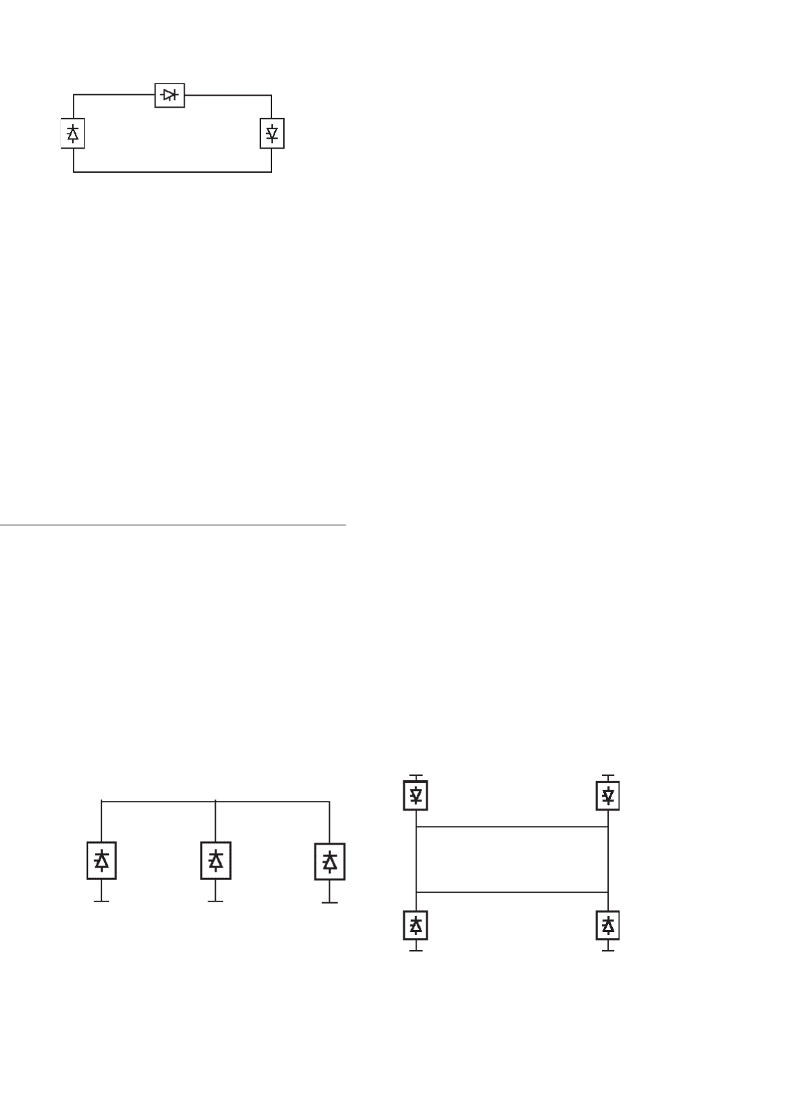
FIGURE 30.19 Series tap.
Fig. 30.18. In general, overvoltages entering from the ac bus are
limited by the ac bus arresters; similarly, overvoltages entering
the converter from the dc line are limited by the dc arrestor.
The ac and dc filters have their respective arrestors also. Crit-
ical components such as the valves have their own arrestors
placed close to these components. The protective firing of a
valve is used as a back-up protection for overvoltages in the
forward direction. Owing to their varied duty, these arrestors
are rated accordingly for the location used. For instance, the
converter arrestor for the upper bridge is subjected to higher
energy dissipation than for the lower bridge.
Since the evaluation of insulation coordination is quite com-
plex, detailed studies are often required with dc simulators to
design an appropriate insulation coordination strategy.
30.5 MTDC Operation
Most HVDC transmission systems are two-terminal systems. A
multiterminal dc system (MTDC) has more than two terminals
and there are two existing installations of this type. There are
two possible ways of tapping power from an HVDC link, i.e.
with series or parallel taps.
30.5.1 Series Tap
A monopolar version of a three-terminal series dc link is shown
in Fig. 30.19. The system is grounded at only one suitable
location. In a series dc system, the dc current is set by one ter-
minal and is common to all terminals; the other terminals are
(a) (b)
FIGURE 30.20 Parallel tap: (a) radial type and (b) mesh type.
operated at a constant delay angle for a rectifier and CEA for
inverter operation with the help of transformer tap changers.
Power reversal at a station is done by reversing the dc voltage
with the aid of angle control.
No practical installation of this type exists in the world at
present. From an evaluation of ratings and costs for series taps,
it is not practical for the series tap to exceed 20% of the rating
for a major terminal in the MTDC system.
30.5.2 Parallel Tap
A monopolar version of a three-terminal parallel dc link is
shown in Fig. 30.20. In a parallel MTDC system, the system
voltage is common to all terminals. There are two variants
possible for a parallel MTDC system: radial or mesh. In a
radial system, disconnection of one segment of the system will
interrupt power from one or more terminals. In a mesh system,
the removal of one segment will not interrupt power flow
providing the remaining links, the capability of carrying the
required power.
Power reversal in a parallel system will require mechanical
switching of the links as the dc voltage cannot be reversed.
From an evaluation of ratings and costs for parallel taps, it
is not practical for the parallel tap to be less than 20% of the
rating for a major terminal in the MTDC system.
There are two installations of parallel taps existing in the
world. The first is the Sardinia–Corsica–Italy link where a
50 MW parallel tap at Corsica is used. Since the principal ter-
minals are rated at 200 MW, a commutation failure at Corsica
can result in very high overcurrents (typically 7 pu); for this
reason, large smoothing reactors (2.5 H) are used in this link.
The second installation is the Quebec–New Hampshire
2000 MW link where a parallel tap is used at Nicolet. Since
the rating of Nicolet is at 1800 MW, the size of the smoothing
reactors was kept to a modest size.
30.5.3 Control of MTDC System
Although several control methods exist for controlling MTDC
systems, the most widely utilized method is the so-called
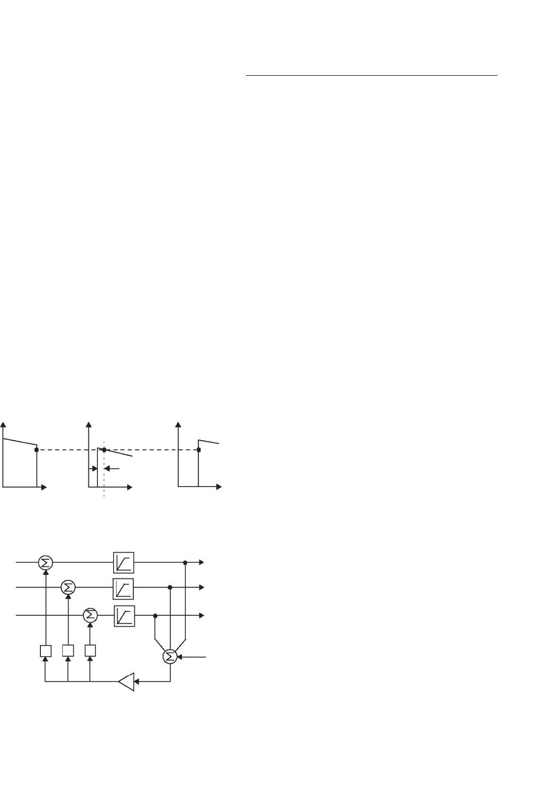
30 HVDC Transmission 787
current margin method, which is an extension of the control
method, used for two-terminal dc systems.
In this method, the voltage setting terminal (VST) oper-
ates at the angle limit (minimum alpha or minimum gamma)
while the remaining terminals are controlling their respective
currents. The control law that is used sets the current reference
at the voltage setting terminal according to
I
jref
= I (30.5)
where I is known as the current margin.
The terminal with the lowest voltage ceiling acts as the VST.
An example of the control strategy is shown in Fig. 30.21
for a three-terminal dc system with one rectifier, REC and two
inverters, INV 1 at 40% and INV2 at 60% rating. The REC 1
and INV 2 terminals are maintained in current control, while
INV 1 is the VST operating in CEA mode.
Due to the requirement to maintain current margin for the
MTDC system at all times, a centralized current controller,
known as the current reference balancer (CRB) (Fig. 30.22),
is required. With this technique, reliable two-way telecommu-
nication links are required for current reference coordination
purposes. The current orders, I
ref1
−I
ref3
, at the terminals must
satisfy the control law according to Eq. (30.5). The weighting
factors (K
1
, K
2
, and K
3
) and limits are selected as a function
of the relative ratings of the terminals.
V
d
V
d
V
d
I
d
I
d
∆I
I
d
REC1
INV1 INV2
FIGURE 30.21 Current margin method of control for MTDC system.
LIMITERS
I
ref1
I
ref2
I
ref3
I
margin
High Gain Amplifier
Weighting
Factors
I
'
ref3
I
'
ref2
I
'
ref1
K
1
K
2
K
3
+
+
+
+
+
+
+
+
+
−
FIGURE 30.22 Current reference balancer.
30.6 Application
30.6.1 HVDC Interconnection at Gurun
(Malaysia)
The 240/600 MW HVDC interconnection between Malaysia
and Thailand is a major first step in implementing elec-
tric power network interconnections in the ASEAN region
(Fig. 30.23). It is jointly undertaken by two utilities, Tenaga
Nasional Berhad (TNB) of Malaysia and Electricity Gener-
ating Authority of Thailand (EGAT). This will be the first
HVDC project for both these utilities. The HVDC intercon-
nection consists of a 110 km HVDC line (85 km owned by TNB
and 25 km owned by EGAT) with the dc converter stations at
Gurun in the Malaysian side and Khlong Ngae in the Thai-
land side. The scheme entered into commercial operation in
2000. The interconnection provides a range of diverse benefits
such as:
• Spinning reserve sharing.
• Economic power exchange – commercial transactions.
•
Emergency assistance to either ac system.
• Damping of ac system oscillations.
•
Reactive power support (voltage control).
• Deferment of generation plant up.
30.6.1.1 Power Transmission Capacity
The converter station is presently constructed for monopolar
operation for power transfer of 240 MW in both directions
with provisions for future extensions to a bipole configuration
giving a total power transfer capability of 600 MW. The HVDC
line is constructed with two pole conductors to cater for the
second 240 MW pole. Full-length neutral conductors are used
instead of ground electrodes because of high land costs and
inherently high values of soil resistivity.
The monopole is rated for a continuous power of 240 MW
(240 kV, 1000 A) at the dc terminal of the rectifier station.
In addition, there is a 10 minutes overload capability of
up to 450 MW, which may be utilized once per day when
all redundant cooling equipment is in service (Tables 30.5
and 30.6).
The HVDC interconnection scheme is capable of continu-
ous operation at a reduced dc voltage of 210 kV (70%) over
the whole load range up to the rated dc current of 1000 A with
all redundant cooling equipment in service.
30.6.1.2 Performance Requirements
A high degree of energy availability was a major design
objective. Guaranteed targets for both stations are:
Energy availability > 99.5%.
Forced energy unavailability < 0.43%.
Forced outage rate < 5.4 outages per year.
788 V. K. Sood
Malaysia
2x60 MVA
Tuned to 11/13/27 harmonics
PLC
PLC
PLC
PLC
3x60 MVA 3x60 MVA
Active dc filterActive dc filter
PLC
PLC
PLC
PLC
12/24
12/24
2x42 MVA
1x84 MVA
Tuned to 12/24/36 harmonics
Thailand
224 kV
EGAT
TNB
275 kV
FIGURE 30.23 One-line diagram of the HVDC interconnection between Malaysia and Thailand.
30.6.1.3 Technical Information
TABLE 30.5 Main data 1
Monopolar operation Rectifier (Malaysia) Inverter (Thailand)
DC power, P
dn
Rated 240 MW (Stage 1) 240 MW
Maximum overload (10 min). 450 MW
Minimum (10% of rated) 24 MW
DC current, I
dn
1000 A 1000 A
DC voltage, U
dn
240 kV 293.5 kV
Firing angle, alpha 15.0
◦
–
Extinction angle, gamma – 19.6
◦
Transformer secondary voltage, U
v
122.2 kV 122.2 kV
Converter reactive power, Q
dc
133.3 MVAr 150.9 MVAr
Reduced dc voltage operation 210 kV (70% dc voltage)
AC system voltage 275 kV, 50 Hz 224 kV, 50 Hz
DC transmission line distance 110 kms
TABLE 30.6 Main data 2
Main equipment GURUN converter station
Smoothing reactor 100 mH
DC filter Active type dc filters including passive type (12th/24th harmonics)
AC filter 2 ×60 MVAr (11/13/27)
Reactive power compensation 3 ×60 MVAr C-shunt
Power thyristor: Type T1501 N75T-S34
Diameter 100 mm
Blocking voltage 7.5 kV repetitive, 8.0 kV non-repetitive
Maximum dc current 1550 A. 120
◦
electrical. T
c
= 60
◦
C
Maximum effective current 3240 A
Converter transformer Single-phase, three winding
Rated power = 275 kV/116 MVA
Transmission line:
Pole conductor Cardinal ACSR 546 mm
2
, twin conductors per pole
Neutral conductor Hen ACSR 298 mm
2
30 HVDC Transmission 789
30.6.1.4 Major Technical Features
The station incorporates the latest state-of-the-art technol-
ogy in power electronics and control equipment. The features
include:
• A fully decentralized control and protection system.
• Active dc filter technology.
• Hybrid dc current shunt measuring devices.
• A triple-tuned ac filter.
30.7 Modern Trends
30.7.1 Converter Station Design of the 2000s
The 1500 MW, ±500 kV Rihand–Delhi HVDC transmission
system (commissioned in 1991) serves as an example of a
typical design of the last decade. Its major design aspects
were:
• Stations employ water-cooled valves of indoor design
with the valves arranged as three quadruple valves
suspended from the ceiling of the valve hall.
• Converter transformers are one-phase, three-winding
units situated close to the valve hall with their bushings
protruding into the valve hall.
• AC filtering is done with conventional, passive, double-
tuned, and high-pass units employing internally-fused
capacitors and air-cored reactors; these filters are
mechanically switched for reactive power control.
• DC filtering is done with conventional, passive units
employing a split smoothing reactor consisting of both
an oil-filled reactor and an air-cored reactor.
• DC current transformer (DCCT) measurement is based
on a zero-flux principle.
• Control and protection hardware is located in a control
room in the service building in between the two valve
halls. The controls still employed some analog parts, par-
ticularly for the protection circuits. The controls were
duplicated with an automatic switchover to hot standby
for reliability reasons.
This design was done in the 1980s to meet the require-
ments of the day for increased reliability and performance
requirements, i.e. availability, reduced losses, higher overload
capability, etc. However, these requirements led to increased
costs for the system.
The next generation equipment is now being spearheaded
by a desire to reduce costs and make HVDC as competitive as
ac transmission. This is being facilitated by the major devel-
opments of the past decade that have taken place in power
electronics. Therefore, the following will influence the next
generation HVDC equipment.
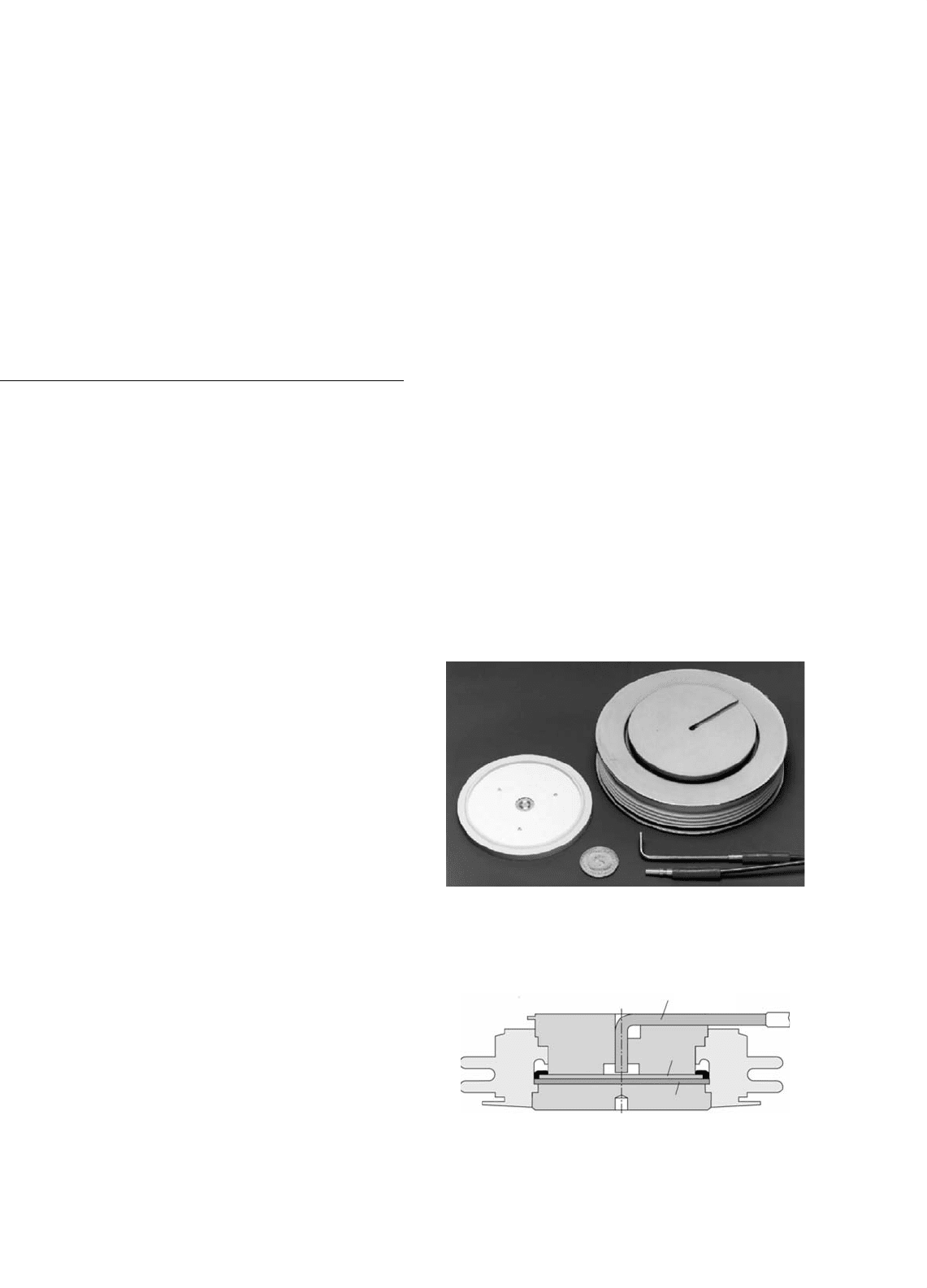
30.7.1.1 Thyristor Development
The HVDC thyristors are now available with a diameter of
150 mm at a rating of 8–9 kV and power-handling capacity of
1500 kW, which will lead to a dramatic decrease in the number
of series connected components for a valve with consequential
cost reductions and improvement in reliability.
The development of the LTT (Figs. 30.24 and 30.25) is likely
to eliminate the electronic unit (with their high number of
electronic components) for generating the firing pulses for
the thyristor (Fig. 30.26). The additional functional require-
ments of monitoring and protection of the device are being
incorporated also.
Both of the above developments present the possibility of
achieving compact valves that can be packaged for outdoor
construction thereby reducing the overall cost and reliability
of the station.
30.7.1.2 Higher DC Transmission Voltages
For long distance transmission, there is a tendency to use a
high voltage to minimize the losses. The typical transmission
voltage has been ±500 kV, although the Itaipu project in Brazil
uses 600 kV. The transmission voltage has to be balanced
against the cost of insulation. The industry is considering
raising the voltage to ±800 kV.
FIGURE 30.24 Silicon wafer and construction of the LTT. The light
guides appear in the bottom right-hand corner.
Light pipe
Cu
Cu
Mo
Si
FIGURE 30.25 Cross section of the LTT with the light pipe entry.
790 V. K. Sood
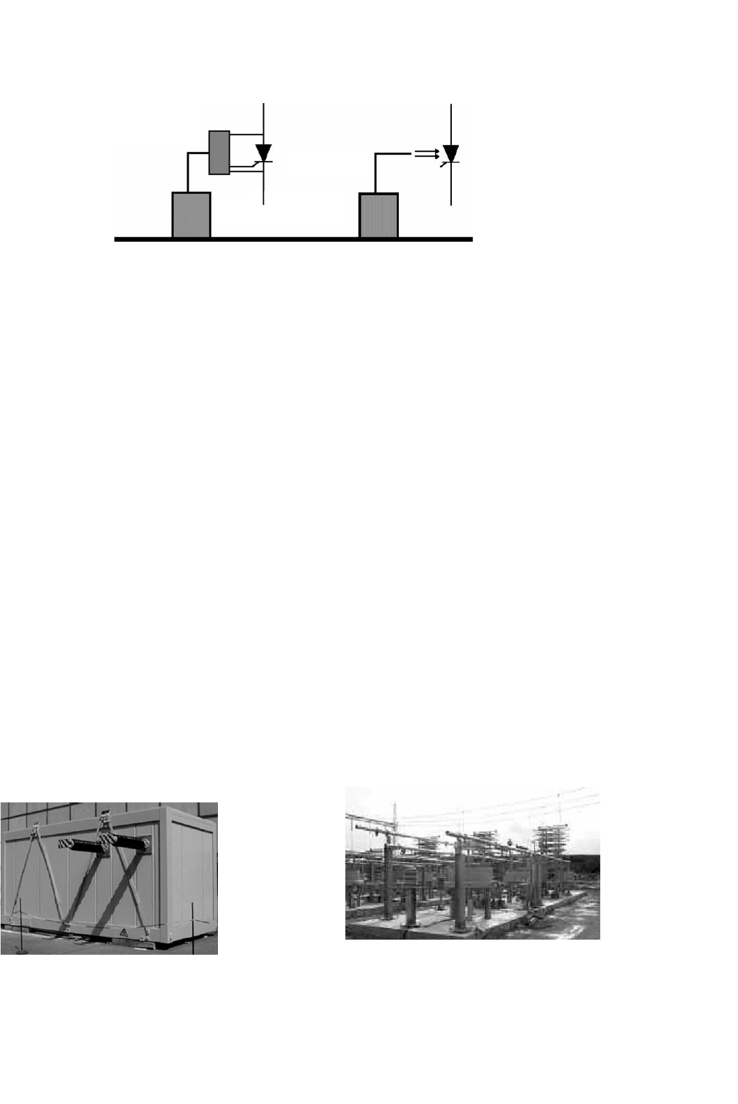
Electrical triggered
Gate Electronics Unit
Optical Pulse Generator
and Control Electronics
Optical fiber
Light triggered
FIGURE 30.26 Conventional firing vs light triggered firing.
30.7.1.3 Controls
It is now possible to operate an HVDC scheme into an
extremely weak ac system, even with short-circuit capacity
down to unity.
Using programmable digital signal processors (DSPs) has
resulted in a compact and modular design that is low cost;
furthermore, the number of control cubicles has decreased
by a factor of almost 10 times in the past decade. Now all
control functions are implemented on digital platforms. The
controls are fully integrated having monitoring, control and
protection features. The design incorporates self-diagnostic
and supervisory characteristics. The controls are optically cou-
pled to the control room for reliable operation. Redundancy
and duplication of controls is resulting in very high reliability
and availability of the equipment.
30.7.1.4 Outdoor Valves
The introduction of air-insulated, outdoor valves will reduce
the cost requirements for a valve hall. The use of a modular,
compact design that can be preassembled in the manufactur-
ing plant will save installation time and provide for a flexible
station layout. This design has been feasible because of the
development of a composite insulator for dc applications that
is used as a communications channel for fiber-optics, cooling
water, and ventilation air between the valve-unit and ground.
FIGURE 30.27 Compact outdoor container with an active dc filter.
30.7.1.5 Active DC Filters
This development, made possible due to advances in power
electronics and microprocessors, has resulted in a more effi-
cient dc filter operating over a wide spectrum of frequencies
and provides a compact design (Fig. 30.27).
30.7.1.6 AC Filters
Conventional ac filters used passive components for tuning
out certain harmonic frequencies. Due to the variations in
frequency and capacitance, physical aging and thermal char-
acteristics of these tuned filters, the quality factors for the filters
were typically about 100–125, which meant that the filters
could not be too sharply tuned for efficient harmonic filter-
ing. The advent of electronically tunable inductors based on
the transductor principal, means that the Q-factors could now
approach the natural one of the inductor. This will lead to
much more enhanced filtering capacities (Fig. 30.28).
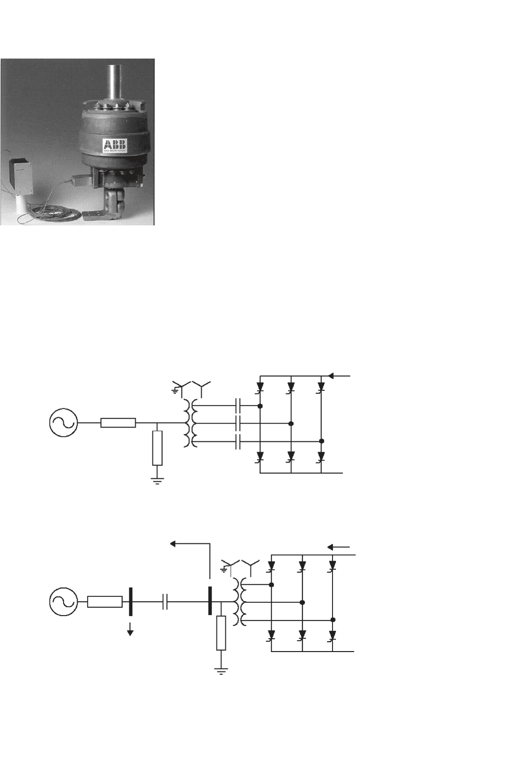
30.7.1.7 AC–DC Current Measurements
The new optical current transducers utilize a precision shunt
at high potential. A small optical fiber link between ground
and high potential is utilized resulting in a lower probability
of a flashover. The optical power link transfers power to high
potential for use in the electronics equipment. The optical data
link transfers data to ground potential. This transducer results
FIGURE 30.28 Installation of the triple-tuned filter at the Gurun station
in Malaysia.
30 HVDC Transmission 791
FIGURE 30.29 The optical current transducer.
in high reliability, compact design, and efficient measurement
(Fig. 30.29).
30.7.1.8 New Topologies
Two new topological changes to the converter design will
impact greatly on future designs.
(a)
(b)
System bus
AC Filters
T
4
T
6
T
2
T
5
T
5
T
2
T
6
T
4
T
3
T
3
T
1
T
1
T
T
S
S
R
R
V
d
V
d
C
R
C
S
C
T
Z
s
I
d
I
d
Filter bus
AC Filters
Z
s
FIGURE 30.30 (a) Capacitor-commutated converter circuit and (b) controlled series capacitor converter circuit.
1. Series compensated commutation: There are two
variants to this topology: the capacitor-commutated
converter (CCC) (Fig. 30.30a) and the controlled series
capacitor converter (CSCC) (Fig. 30.30b). Essentially,
the behavior of the two variants is very similar. The
insertion of a capacitor in series with the converter
transformer leakage reactance causes a major reduction
in the commutation impedance of the converter result-
ing in a reduction in the reactive power requirement
of the converter. An increase in the size of the series
capacitor can even result in the converter operation at
a leading power factor if so desired. However, the neg-
ative impact of lower commutation impedance results
in additional stresses on the valves and transformers
and additional cost implications [7].
The first CCC back-back converter station (rated at
2 ×550 MW), has been put into service at Garabi, on
the Brazilian side of the Uruguay river. The system
interconnects the electrical systems of Argentina and
Brazil.
2. Voltage source converters (VSC): The use of self-
commutation with the new generation switching
devices (i.e. gate turn off thyristors (GTOs) and insu-
lated gate bipolar transistors (IGBTs) has resulted
in the topology of a VSC (Fig. 30.31) as opposed
792 V. K. Sood
FIGURE 30.31 Voltage source converter topology.
to the conventional converter using line-commutated
thyristors and current source converter (CSC) topol-
ogy. The VSC, being self-commutated, can control
active/reactive power and, with PWM techniques, con-
trol harmonic generation as well. The application
of such circuits is presently limited by the switch-
ing losses and ratings of available switching devices.
The ongoing advances in power electronic devices are
expected to have a major impact on the future applica-
tion of this type of converter in HVDC transmission.
New application areas, particularly in distribution sys-
tems, are being actively investigated with this topology.
Table 30.7 provides a partial list of the HVDC links in
operation using this technique.
One major difficulty for the use of the VSC is the threat
posed to the valves from a short circuit on the dc line. Unlike
the CSC where the valves are inherently protected against
short-circuit currents by the presence of the smoothing reac-
tor, the VSC is relatively unprotected. For this reason, the VSC
applications are almost always used with dc cables where the
risk of a dc line short circuit is greatly reduced.
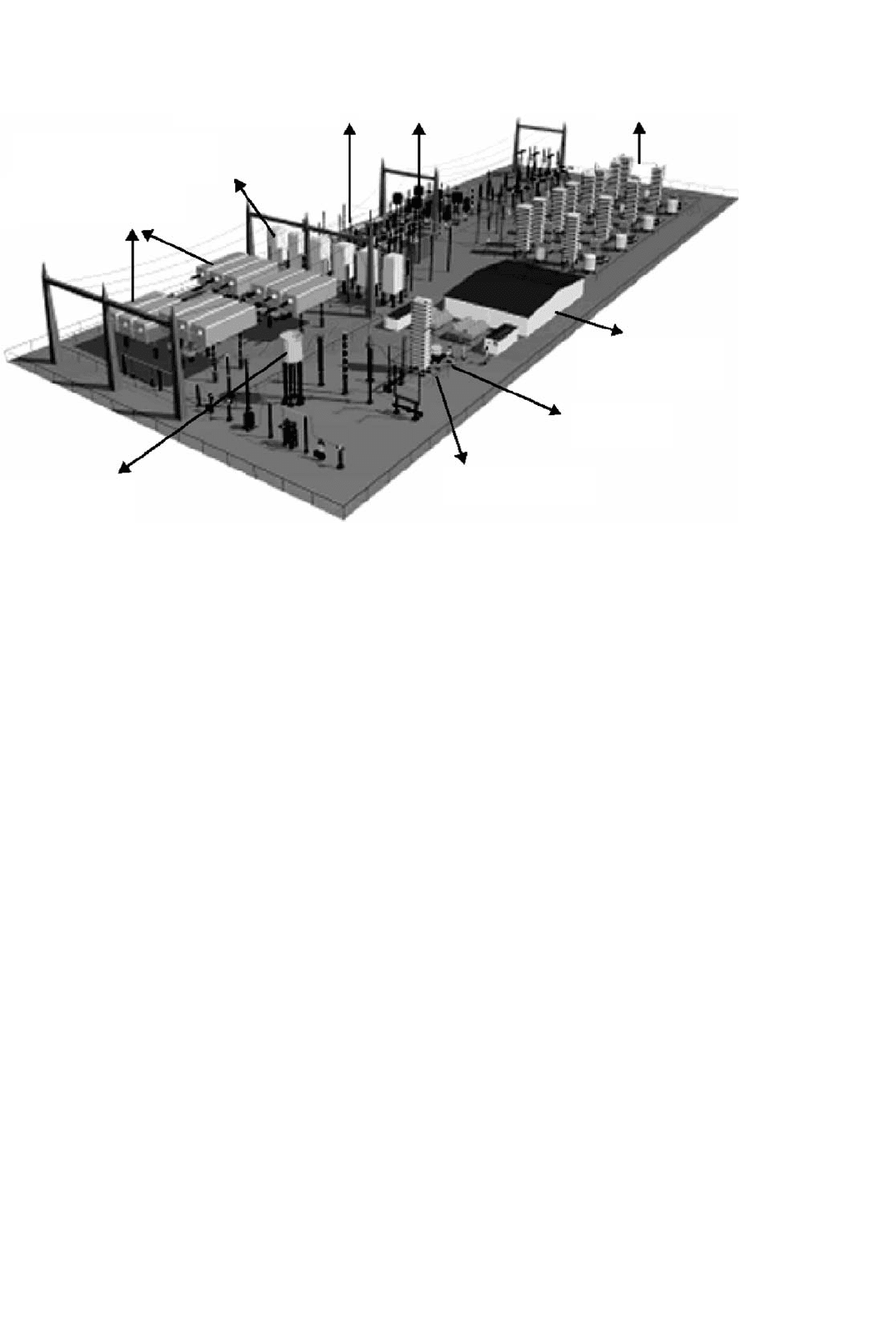
30.7.1.9 Compact Station Layout
The advances discussed above have resulted in marked
improvement of the footprint requirement of the compact
TABLE 30.7 Applications of HVDC light technology
No. Project Rating Distance (km) Application Commissioned
MVA kV
1 Hellsjon 3 ±10 10 AC–DC conversion Mar. 1997
2 Gotland 50 ±80 70 Feed from wind power generation June 1999
3 Tjaereborg 7 ±10 4 Feed from wind power generation Aug. 1999
4 Directlink 180 ±140 65 Asynchronous interconnection Dec. 1999
5 Murraylink 220 ±140 180 Asynchronous interconnection 2002
6 Shoreham 330 ±140 40 Cross sound cable link 2002
7 Troll A 2 ×42 ±60 70 Gas production offshore platform 2005
station [8] of the year 2000 which has about 24% space require-
ment of the comparable HVDC station designed in the past
decade (Fig. 30.32).
30.8 HVDC System Simulation
Techniques
Modern HVDC systems incorporate complex control and pro-
tection features. The testing and optimization of these features
require powerful tools that are capable of modeling all facets
of the system and have the flexibility to do the evaluation in a
rapid, effective, and cost efficient manner.
30.8.1 DC Simulators and TNAs [9]
For decades, this has been achieved with the aid of physi-
cal power system simulators or transient network analyzers
(TNAs) which incorporate scaled physical models of all power
system elements (three-phase ac network lines/cables, sources
as e.m.f. behind reactances, model circuit breakers for pre-
cisely timed ac system disturbances, transformers (system
and convertor transformers with capacity to model saturation
characteristics), filter capacitors, reactors, resistors, arrestors,
and machines). Until the 1970s, these were built with analog
components. However, with the developments in micropro-
cessors, it is now feasible to utilize totally digital simulators
operating in real time for even the most complex HVDC sys-
tem studies. Most simulators operating scale is in the range
20–100 V dc, 0.2–1 A ac and at power frequency of 50 or
60 Hz. The stray capacitances and inductances are, however,
not normally represented since the simulator is primarily used
to assess control system behavior and temporary overvoltages
of frequencies below 1000 Hz. Due to the developments of
flexible ac transmission systems (FACTS) application, most
modern simulators now include similarly scaled models of
HVDC converters, static compensators, and other thyristor-
controlled equipments. The controls of these equipments
are usually capable of realistic performance during transients
such as the ac faults and commutation failure. The limited
30 HVDC Transmission 793
Active DC filter
Valve cooling
Control & Service
Building
Smoothing reactor
Outdoor HVDC valves
Commutation capacitors
Converter transformers
AC filters
ConTune & high pass filters
FIGURE 30.32 Layout of a compact HVDC station (graphic reproduced here courtesy of ABB).
availability of adequate models of some of the system ele-
ments restricts the scope of the studies which can be completed
entirely by means of the simulator. Due to the scaling prob-
lems, the losses in the simulator may be disproportionately
high and need to be partly compensated by electronic cir-
cuits (negative resistances) to simulate appropriate damping
of overvoltages and other phenomena.
30.8.2 Digital Computer Analysis
The main type of program employed for studies is an elec-
tromagnetic transients program (EMTP) that solves sets of
differential equations by step-by-step integration methods.
The digital program must allow for the modeling of both the
linear and non-linear components (single- and three-phase)
and of the topological changes caused; for example, by valve
firing or by circuit-breaker operation. Detailed modeling of
the converter control system is necessary depending on the
type of study.
The EMTP has become an industrial standard analysis tool
for power systems and is widely used. The program has had a
checkered history and numerous variants have appeared. Ini-
tially, the development of the program was supported by the
Bonneville Power Administration (BPA). Some of the draw-
backs in the capabilities of EMTP became more pronounced
as the modeling of FACTS with power electronic switches and
VSCs became more desirable.
Some of the drawbacks of the original EMTP version were:
1. The use of a fixed timestep that did not take into
account the relatively long periods of inaction during
non-switching events. This results in unnecessarily
long simulation times and huge amounts of data to
be manipulated. This is particularly problematic for
simulating power electronic converters.
2. The use of a fixed timestep results in the mod-
eled switches chopping inductive current that causes
numerical oscillations. The use of artificial RC “snub-
bers” helped to alleviate some of these problems. The
choice of the snubber capacitor was a function of
the magnitude of the current to be chopped and the
timestep size.
3. The use of the trapezoidal integration method results
in numerical oscillations when the network admittance
matrix to be inverted becomes singular. This is the
direct result of modeling switches as truly either ON
or OFF without representation of their intermediate
non-linear characteristics.
4. The requirement of a one-timestep delay between the
main program and the transient analysis of control
systems (TACS) subroutine for controls simulation.
5. The use of new VSCs with multiple switching per cycle
made the problem of switching “jitter” much more
evident.
6. The lack of user-friendly input and output processors.